EP1102642B1 - Material classifying apparatus - Google Patents
Material classifying apparatus Download PDFInfo
- Publication number
- EP1102642B1 EP1102642B1 EP99928375A EP99928375A EP1102642B1 EP 1102642 B1 EP1102642 B1 EP 1102642B1 EP 99928375 A EP99928375 A EP 99928375A EP 99928375 A EP99928375 A EP 99928375A EP 1102642 B1 EP1102642 B1 EP 1102642B1
- Authority
- EP
- European Patent Office
- Prior art keywords
- vibratory conveyor
- separation section
- plenum chamber
- air
- heavier
- Prior art date
- Legal status (The legal status is an assumption and is not a legal conclusion. Google has not performed a legal analysis and makes no representation as to the accuracy of the status listed.)
- Expired - Lifetime
Links
Images


Classifications
-
- B—PERFORMING OPERATIONS; TRANSPORTING
- B03—SEPARATION OF SOLID MATERIALS USING LIQUIDS OR USING PNEUMATIC TABLES OR JIGS; MAGNETIC OR ELECTROSTATIC SEPARATION OF SOLID MATERIALS FROM SOLID MATERIALS OR FLUIDS; SEPARATION BY HIGH-VOLTAGE ELECTRIC FIELDS
- B03B—SEPARATING SOLID MATERIALS USING LIQUIDS OR USING PNEUMATIC TABLES OR JIGS
- B03B4/00—Separating by pneumatic tables or by pneumatic jigs
- B03B4/02—Separating by pneumatic tables or by pneumatic jigs using swinging or shaking tables
-
- B—PERFORMING OPERATIONS; TRANSPORTING
- B07—SEPARATING SOLIDS FROM SOLIDS; SORTING
- B07B—SEPARATING SOLIDS FROM SOLIDS BY SIEVING, SCREENING, SIFTING OR BY USING GAS CURRENTS; SEPARATING BY OTHER DRY METHODS APPLICABLE TO BULK MATERIAL, e.g. LOOSE ARTICLES FIT TO BE HANDLED LIKE BULK MATERIAL
- B07B4/00—Separating solids from solids by subjecting their mixture to gas currents
- B07B4/08—Separating solids from solids by subjecting their mixture to gas currents while the mixtures are supported by sieves, screens, or like mechanical elements
Definitions
- the present invention is generally directed to a material classifying apparatus according to the first part of claim 1.
- a material classifying apparatus is known from FR-A-1361346 .
- a material may be utilized in an application such that it becomes contaminated but is otherwise reusable if it can be reclaimed. It is known that in almost all commercial settings it is important to economize in order to maintain competitive costs and, additionally, it is equally important to limit commercial waste that often presents significant expensive disposal problems. For these reasons, there have been significant efforts to develop techniques for reclaiming and/or separating materials in a cost effective and efficient manner.
- shot is utilized in the manufacture of castings to finish the castings by subjecting them to a shot blast treatment.
- This finishing technique is highly effective but, by its very nature, produces refuse in the form of fines and dust that must be separated from the shot if it is to be suitable for reuse.
- the large volume of shot that is required for shot blast treatments means that a significant volume of material must be reclaimed.
- U.S. Patent No. 2 815 858 illustrates a sorting system including a vibrating table and a substantially closed-loop air circulation system. While the system includes a chamber and a sorting zone, no walls are arranged in the sorting zone to form separate, stable fluidzing zones.
- U.S. Patent No. 3 161 483 illustrates a variety of devices for fluidizing a material using a vibrating table or vessel.
- the devices include air driven through the material to fluidize the material.
- the present invention is directed to overcoming one or more of the foregoing problems and achieving one or more of the resulting objects.
- the present invention comprises a known material classifying apparatus with the features of the second part of claim 1.
- the plenum chamber and the material separation section define a portion of a closed loop air circulation system and the apparatus includes means for isolating the material separation section from the remainder of the vibratory conveyor to maintain a desired air pressure within the closed loop air circulation system.
- the fluidizing deck advantageously has a plurality of air passageways within the closed loop air circulation system to permit air to continuously flow from the plenum chamber through the air passageways in the fluidizing deck and back to the plenum chamber to fluidize the fluidized material which may comprise a material and separate the other of the materials which may comprise fines therefrom.
- the stabilizing means advantageously comprises a grate suitably disposed on an upper surface of the fluidizing deck and formed of at least a plurality of material retention walls extending generally across the material separation section in spaced relation to define a plurality of stable fluidizing zones
- the material classifying apparatus also includes an exhaust hood above the material separation section which, together with the plenum chamber, forms a portion of the closed loop air circulation system for fluidizing the material and separating the fines from the material for removal through the exhaust hood.
- the vibratory conveyor of the present invention also includes a screen section upstream of the material separation section having a mesh size to permit the material and fines to pass from a first level of the vibratory conveyor through the screen to a second, lower level while retaining any overs material larger than the material at the first level.
- an overs material diverting wall is advantageously provided downstream of the screen section of the vibratory conveyor at the first level and upstream of the material separation section to cause overs material to be diverted from the vibratory conveyor to a collection box alongside the vibratory conveyor.
- the closed loop air circulation system includes not only an exhaust hood above the material separation section of the vibratory conveyor but also means defining a continuous air flow path from the exhaust hood to the plenum chamber and means for removing the fines along the continuous air flow path at a point upstream of the plenum chamber.
- the continuous air flow path is advantageously defined by an air duct flexibly connected to the exhaust hood and extending therefrom together with an air duct extending toward the plenum chamber and flexibly connected thereto, and an air blower is advantageously provided for circulating air from the exhaust hood to the plenum chamber through these air ducts.
- the refuse material removing means advantageously includes a cyclone separator positioned downstream of the exhaust hood for removing the fines and a dust collector positioned downstream of the cyclone separator for removing dust at a point upstream of the plenum chamber.
- the reference numeral 10 designates generally a material classifying apparatus in accordance with the present invention.
- the apparatus 10 includes a vibratory conveyor generally designated 12 for conveying two classifiable materials which may comprise a heavier material and fines from an inlet end 14 through a material separation section 16 to an outlet end 18 located downstream of the material separation section 16 of the vibratory conveyor 12.
- a plenum chamber 20 directs air upwardly through the heavier material and the fines in the material separation section 16 of the vibratory conveyor 12 to cause fluidization of the heavier material and separation of the fines therefrom.
- the material classifying apparatus 10 is formed such that the material separation section 16 of the vibratory conveyor 12 comprises a fluidizing deck 22 for supporting the heavier material and the fines while accommodating passage of air upwardly from the plenum chamber 20 through the heavier material. With this arrangement, the apparatus 10 further includes means for stabilizing the heavier material on the fluidizing deck 22 to produce a uniform air flow through the heavier material to facilitate separation of the fines from the heavier material upstream of the outlet end 18 of the vibratory conveyor 12.
- the plenum chamber 20 and the material separation section 16 define a portion of a closed loop air circulation system which is generally designated 24.
- the apparatus 10 also includes means for isolating the material separation section 16 from the remainder of the vibratory conveyor 12, such as flexible flap seals 26 and 28, to maintain a desired air pressure within the closed loop air circulation system 24.
- the flexible flap seals 26 and 28 engage the heavier material and lighter fines that are being conveyed by the vibratory conveyor 12 at both an upstream end 16a and downstream end 16b of the material separation section 16, respectively.
- the fluidizing deck 22 has a plurality of air passageways 30 within the closed loop air circulation system 24 and, by comparing Figs. 3 , 6 and 7 , the position of the fluidizing deck 22 within the closed loop air circulation system 24 will be understood. With this arrangement, it will be appreciated that air is permitted to continuously flow from the plenum chamber 20 through the air passageways 30 in the fluidizing deck 22 and back to the plenum chamber 20 to continuously fluidize the heavier material and separate the lighter fines therefrom.
- the stabilizing means comprises a grate 32 on an upper surface 22a of the fluidizing deck 22 having at least a plurality of material retention walls 32a that are preferably vertically upstanding.
- the material retention walls 32a extend across, and preferably generally transversely of, the material separation section 16 in preferably longitudinally spaced relation to define a plurality of stable fluidizing zones such as 34 through 40.
- the grate 32 may also include vertically upstanding support walls 32b extending generally in the direction of material flow through the material separation section 16.
- the material separation section may advantageously include an upstream weir 32c and a downstream weir 32d defining additional stable fluidizing zones immediately upstream and downstream of the grate 32, respectively.
- the upstream and downstream weirs 32c and 32d may suitably be made adjustable, as shown, in order to adjust the size of the fluidizing zones defined thereby. By so doing, it is possible to vary the effective area of the fluidizing deck 22 between limits determined by the degree of adjustability that may be achieved by moving the upstream and downstream weirs 32c and 32d longitudinally toward and away from each other.
- the vibratory conveyor 12 also includes a screen section 42 upstream of the material separation section 16 having a mesh size to permit the heavier material in the form of shot as well as the lighter fines to pass from a first level 12a of the vibratory conveyor 12 through the screen section 42 to a second, lower level 12b while retaining any overs material larger than the heavier material at the first level 12a.
- the screen section 42 will serve to separate the shot and fines and dust from any larger overs material such as large portions of a sand mold or sand core, or a casting that might somehow reach the vibratory conveyor 12.
- an overs material diverting wall 44 is provided downstream of the screen section 42 of the vibratory conveyor 12 at the first level 12a and upstream of the material separation section 16 in order to cause overs material to be diverted from the vibratory conveyor 12 to an overs material collection box 46 positioned alongside the vibratory conveyor 12.
- the closed loop air circulation system 24 includes an exhaust hood 48 positioned above the material separation section 16 of the vibratory conveyor 12.
- the closed loop air circulation system 24 also includes means defining a continuous air flow path extending from the exhaust hood 48 back to the plenum chamber 20 and, more specifically, it includes an air duct 50 flexibly connected as at 52 to the exhaust hood 48 and extending therefrom and an air duct 54 extending toward the plenum 20 and flexibly connected thereto as at 56.
- the closed loop air circulation system 24 includes an air blower 58 to circulate air from the exhaust hood 48, through the air duct 50, through the air duct 54, and back to the plenum chamber 20.
- the closed loop air circulation system 24 includes means for removing fines along the continuous air flow path at a point upstream of the plenum chamber 20.
- the fines removing means includes a cyclone separator 60 for removing fines and dust or other refuse that has been separated from the heavier material in the material separation section 16 and also includes a dust collector 62 downstream of the cyclone separator 60 for removing dust, i.e., the fines are removed by the cyclone separator 60 and the dust is removed by the dust collector 62 so that clean air will be supplied to the plenum chamber 20.
- the cyclone separator 60 and the dust collector 62 are both positioned for removing the fines and dust upstream of the plenum chamber 20 and, preferably, upstream of the blower 58.
- the closed loop air circulation system 24 may include an inlet air diffuser or screen 64 at the upstream end 20a of the plenum chamber 20 to provide uniformly distributed air to the material separation section 16 of the vibratory conveyor 12.
- the exhaust hood 48 may be provided with a pair of adjustable plates 66 and 68 defining an airflow path above the material separation section 16 to control air flow velocity through the exhaust hood 48.
- the apparatus 10 also preferably includes a first flexible seal 26 at an upstream end 16a of the material separation section 16 and a second flexible seal 28 at a downstream end of the material separation section 16 as part of the closed loop air circulation system 24.
- the vibratory conveyor 12 conveys shot and fines that are deposited through a feeder 70 that leads from a shot blast apparatus.
- the vibratory conveyor 12 conveys these materials at a first level 12a where they fall through the screen section 42 to a second level 12b at which they are conveyed through the material separation section 16. If there are any overs materials larger than the shot at the first level 12a, they are diverted from the vibratory conveyor 12 by the overs material diverting wall 44 to the overs material collection box 46 alongside the vibratory conveyor 12.
- the stable, uniform airflow fluidizing zones such as 34 through 40 are present immediately above the plenum chamber 20 means that the air from the plenum chamber 20 that has passed through the diffuser 64 is uniformly distributed and passes through the material that is temporarily captured within the fluidizing zones which material serves to further uniformly disperse the air to cause a uniform fluidization of the material above the grate 32 and especially above the material retention walls 32a that is continuing to flow toward the outlet end 18 of the vibratory conveyor 12.
- the fluidizing air causes the fines and dust to be blown upwardly out of the shot where it passes through the exhaust hood 48, the air duct 50, and into the cyclone separator 60.
- the heavier fines are removed while air containing dust continues to flow into the dust collector 62 where the dust is removed leaving only clean air to flow to the blower 58 and then through the air duct 54 into the plenum chamber 20.
- the closed loop air circulation system 24 combined with the grate 32 produces the intended effect of removing the fines and dust due to the stable, uniform airflow fluidizing zones such as 34 through 40 produced by the shot that is temporarily retained therewithin.
- the present invention may find use wherever it is desired to separate two classifiable materials, whether those materials are classified, e.g., as having different terminal velocities as heavier material and lighter fines, as shot and fines and dust, or otherwise. If one of the materials is capable of being fluidized and the other of the materials is capable of being separated therefrom through the action of the fluidizing air, the present invention can be advantageously utilized to achieve a substantially complete material separation and classification.
Abstract
Description
- The present invention is generally directed to a material classifying apparatus according to the first part of
claim 1. Such a material classifying apparatus is known fromFR-A-1361346 - In many industrial applications, it is necessary and/or desirable to be able to separate two classifiable materials that have become or are naturally commingled.
- As one example, a material may be utilized in an application such that it becomes contaminated but is otherwise reusable if it can be reclaimed. It is known that in almost all commercial settings it is important to economize in order to maintain competitive costs and, additionally, it is equally important to limit commercial waste that often presents significant expensive disposal problems. For these reasons, there have been significant efforts to develop techniques for reclaiming and/or separating materials in a cost effective and efficient manner.
- For certain applications, there is a need to separate a heavier material from fines that are lighter, in weight. This typically cannot be accomplished by utilizing an elementary technique such as screening inasmuch as the fines are commonly interspersed throughout the heavier material and, due to their lighter weight, the fines will not settle to the level of the screen to pass through leaving only the heavier material. As a result, it is recognized that applications of this type require techniques that are far more sophisticated.
- Despite this recognition, it is also recognized that the competing considerations of cost and overall effectiveness are of paramount importance. It is likewise often a key factor that the technique for separation and recovery of classifiable materials be sufficiently effective to handle the volume of combined materials that are typically encountered in any particular industrial application(s). In other words, the technique must be capable of separating and recovering classifiable materials in a time frame compatible with the industrial application(s).
- As one example, shot is utilized in the manufacture of castings to finish the castings by subjecting them to a shot blast treatment. This finishing technique is highly effective but, by its very nature, produces refuse in the form of fines and dust that must be separated from the shot if it is to be suitable for reuse. Still additionally, the large volume of shot that is required for shot blast treatments means that a significant volume of material must be reclaimed.
- In order to achieve the reclamation of the shot as a reusable material in a timely manner, it is necessary to separate and remove the fines as a waste product in a high volume operation.
-
U.S. Patent No. 2 815 858 illustrates a sorting system including a vibrating table and a substantially closed-loop air circulation system. While the system includes a chamber and a sorting zone, no walls are arranged in the sorting zone to form separate, stable fluidzing zones. -
U.S. Patent No. 3 161 483 illustrates a variety of devices for fluidizing a material using a vibrating table or vessel. The devices include air driven through the material to fluidize the material. - The present invention is directed to overcoming one or more of the foregoing problems and achieving one or more of the resulting objects.
- Accordingly, it is a principal object of the present invention to provide an apparatus for the classification of materials that are generally of a non-homogenous nature. It is a further object of the present invention to provide a material classifying apparatus for separating a lighter material from a heavier material. Additionally, it is an object of the present invention to provide an apparatus for separating fines from shot by utilizing a fluidizing deck as a portion of a vibratory conveyor.
- To achieve these objects, the present invention comprises a known material classifying apparatus with the features of the second part of
claim 1. - In the exemplary embodiment, the plenum chamber and the material separation section define a portion of a closed loop air circulation system and the apparatus includes means for isolating the material separation section from the remainder of the vibratory conveyor to maintain a desired air pressure within the closed loop air circulation system. The fluidizing deck advantageously has a plurality of air passageways within the closed loop air circulation system to permit air to continuously flow from the plenum chamber through the air passageways in the fluidizing deck and back to the plenum chamber to fluidize the fluidized material which may comprise a material and separate the other of the materials which may comprise fines therefrom. The stabilizing means advantageously comprises a grate suitably disposed on an upper surface of the fluidizing deck and formed of at least a plurality of material retention walls extending generally across the material separation section in spaced relation to define a plurality of stable fluidizing zones Preferably, the material classifying apparatus also includes an exhaust hood above the material separation section which, together with the plenum chamber, forms a portion of the closed loop air circulation system for fluidizing the material and separating the fines from the material for removal through the exhaust hood.
- The vibratory conveyor of the present invention also includes a screen section upstream of the material separation section having a mesh size to permit the material and fines to pass from a first level of the vibratory conveyor through the screen to a second, lower level while retaining any overs material larger than the material at the first level. For this purpose, an overs material diverting wall is advantageously provided downstream of the screen section of the vibratory conveyor at the first level and upstream of the material separation section to cause overs material to be diverted from the vibratory conveyor to a collection box alongside the vibratory conveyor.
- In another respect, the closed loop air circulation system includes not only an exhaust hood above the material separation section of the vibratory conveyor but also means defining a continuous air flow path from the exhaust hood to the plenum chamber and means for removing the fines along the continuous air flow path at a point upstream of the plenum chamber. The continuous air flow path is advantageously defined by an air duct flexibly connected to the exhaust hood and extending therefrom together with an air duct extending toward the plenum chamber and flexibly connected thereto, and an air blower is advantageously provided for circulating air from the exhaust hood to the plenum chamber through these air ducts. As for the refuse material removing means, it advantageously includes a cyclone separator positioned downstream of the exhaust hood for removing the fines and a dust collector positioned downstream of the cyclone separator for removing dust at a point upstream of the plenum chamber.
- Other objects, advantages and features of the present invention will become apparent from a consideration of the following specification taken in conjunction with the accompanying drawings.
-
-
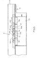
Fig. 1 is a side elevational view, partially in section, of a portion of the material classifying apparatus of the present invention; -
Fig. 2 is a plan view of the portion of the material classifying apparatus illustrated inFig. 1 , -
Fig. 3 is a plan view of the material separation section of the material classifying apparatus ofFig. 1 ; -
Fig. 4 is a cross-sectional view taken generally along the line 4-4 ofFig. 3 ; -
Fig. 5 is a cross-sectional view taken generally along the line 5-5 ofFig. 3 ; -
Fig. 6 is a schematic view illustrating the closed loop air circulation system of the material classifying apparatus ofFig. 1 ; and -
Fig. 7 is a cross-sectional view taken generally along the line 7-7 ofFig. 6 . - In the illustrations given, and with reference first to
Fig. 1 , thereference numeral 10 designates generally a material classifying apparatus in accordance with the present invention. Theapparatus 10 includes a vibratory conveyor generally designated 12 for conveying two classifiable materials which may comprise a heavier material and fines from aninlet end 14 through amaterial separation section 16 to anoutlet end 18 located downstream of thematerial separation section 16 of thevibratory conveyor 12. Aplenum chamber 20 directs air upwardly through the heavier material and the fines in thematerial separation section 16 of thevibratory conveyor 12 to cause fluidization of the heavier material and separation of the fines therefrom. The material classifyingapparatus 10 is formed such that thematerial separation section 16 of thevibratory conveyor 12 comprises a fluidizingdeck 22 for supporting the heavier material and the fines while accommodating passage of air upwardly from theplenum chamber 20 through the heavier material. With this arrangement, theapparatus 10 further includes means for stabilizing the heavier material on the fluidizingdeck 22 to produce a uniform air flow through the heavier material to facilitate separation of the fines from the heavier material upstream of theoutlet end 18 of thevibratory conveyor 12. - In accordance with the present invention, and referring now to
Figs. 1 ,6 , and7 , theplenum chamber 20 and thematerial separation section 16 define a portion of a closed loop air circulation system which is generally designated 24. Theapparatus 10 also includes means for isolating thematerial separation section 16 from the remainder of thevibratory conveyor 12, such asflexible flap seals air circulation system 24. As will be appreciated, theflexible flap seals vibratory conveyor 12 at both anupstream end 16a anddownstream end 16b of thematerial separation section 16, respectively. - As best shown in
Fig. 3 , the fluidizingdeck 22 has a plurality ofair passageways 30 within the closed loopair circulation system 24 and, by comparingFigs. 3 ,6 and7 , the position of the fluidizingdeck 22 within the closed loopair circulation system 24 will be understood. With this arrangement, it will be appreciated that air is permitted to continuously flow from theplenum chamber 20 through theair passageways 30 in the fluidizingdeck 22 and back to theplenum chamber 20 to continuously fluidize the heavier material and separate the lighter fines therefrom. - As shown in
Figs. 3-5 , the stabilizing means comprises agrate 32 on an upper surface 22a of the fluidizingdeck 22 having at least a plurality ofmaterial retention walls 32a that are preferably vertically upstanding. Thematerial retention walls 32a extend across, and preferably generally transversely of, thematerial separation section 16 in preferably longitudinally spaced relation to define a plurality of stable fluidizing zones such as 34 through 40. For structural purposes, thegrate 32 may also include verticallyupstanding support walls 32b extending generally in the direction of material flow through thematerial separation section 16. - As also shown in
Figs. 3 and5 , the material separation section may advantageously include anupstream weir 32c and adownstream weir 32d defining additional stable fluidizing zones immediately upstream and downstream of thegrate 32, respectively. The upstream anddownstream weirs deck 22 between limits determined by the degree of adjustability that may be achieved by moving the upstream anddownstream weirs - As shown in
Fig. 2 , thevibratory conveyor 12 also includes ascreen section 42 upstream of thematerial separation section 16 having a mesh size to permit the heavier material in the form of shot as well as the lighter fines to pass from afirst level 12a of thevibratory conveyor 12 through thescreen section 42 to a second, lower level 12b while retaining any overs material larger than the heavier material at thefirst level 12a. It will be appreciated, for instance, that where thematerial classifying apparatus 10 is utilized to separate fines and dust from shot thescreen section 42 will serve to separate the shot and fines and dust from any larger overs material such as large portions of a sand mold or sand core, or a casting that might somehow reach thevibratory conveyor 12. As shown inFig. 2 , an oversmaterial diverting wall 44 is provided downstream of thescreen section 42 of thevibratory conveyor 12 at thefirst level 12a and upstream of thematerial separation section 16 in order to cause overs material to be diverted from thevibratory conveyor 12 to an oversmaterial collection box 46 positioned alongside thevibratory conveyor 12. - Referring to
Figs. 6 and7 , the closed loopair circulation system 24 includes anexhaust hood 48 positioned above thematerial separation section 16 of thevibratory conveyor 12. The closed loopair circulation system 24 also includes means defining a continuous air flow path extending from theexhaust hood 48 back to theplenum chamber 20 and, more specifically, it includes anair duct 50 flexibly connected as at 52 to theexhaust hood 48 and extending therefrom and anair duct 54 extending toward theplenum 20 and flexibly connected thereto as at 56. Still additionally, the closed loopair circulation system 24 includes anair blower 58 to circulate air from theexhaust hood 48, through theair duct 50, through theair duct 54, and back to theplenum chamber 20. - As also shown in
Fig. 6 , the closed loopair circulation system 24 includes means for removing fines along the continuous air flow path at a point upstream of theplenum chamber 20. The fines removing means includes acyclone separator 60 for removing fines and dust or other refuse that has been separated from the heavier material in thematerial separation section 16 and also includes adust collector 62 downstream of thecyclone separator 60 for removing dust, i.e., the fines are removed by thecyclone separator 60 and the dust is removed by thedust collector 62 so that clean air will be supplied to theplenum chamber 20. In other words, thecyclone separator 60 and thedust collector 62 are both positioned for removing the fines and dust upstream of theplenum chamber 20 and, preferably, upstream of theblower 58. - Still referring to
Fig. 6 , the closed loopair circulation system 24 may include an inlet air diffuser orscreen 64 at the upstream end 20a of theplenum chamber 20 to provide uniformly distributed air to thematerial separation section 16 of thevibratory conveyor 12. It will also be seen inFig. 1 that theexhaust hood 48 may be provided with a pair ofadjustable plates material separation section 16 to control air flow velocity through theexhaust hood 48. As previously described, theapparatus 10 also preferably includes a firstflexible seal 26 at anupstream end 16a of thematerial separation section 16 and a secondflexible seal 28 at a downstream end of thematerial separation section 16 as part of the closed loopair circulation system 24. - From the foregoing, it will be clear that the
material classifying apparatus 10 is particularly well suited for separating fines as well as dust from shot in a continuous process that is highly effective and cost efficient. Thevibratory conveyor 12 conveys shot and fines that are deposited through afeeder 70 that leads from a shot blast apparatus. Thevibratory conveyor 12 conveys these materials at afirst level 12a where they fall through thescreen section 42 to a second level 12b at which they are conveyed through thematerial separation section 16. If there are any overs materials larger than the shot at thefirst level 12a, they are diverted from thevibratory conveyor 12 by the oversmaterial diverting wall 44 to the oversmaterial collection box 46 alongside thevibratory conveyor 12. - As the shot and fines reach the
material separation section 16, they entirely fill thegrate 32, i.e., they fill the plurality of stable, uniform airflow fluidizing zones such as 34 through 40. The fact that the stable, uniform airflow fluidizing zones such as 34 through 40 are present immediately above theplenum chamber 20 means that the air from theplenum chamber 20 that has passed through thediffuser 64 is uniformly distributed and passes through the material that is temporarily captured within the fluidizing zones which material serves to further uniformly disperse the air to cause a uniform fluidization of the material above thegrate 32 and especially above thematerial retention walls 32a that is continuing to flow toward the outlet end 18 of thevibratory conveyor 12. As a result, the fluidizing air causes the fines and dust to be blown upwardly out of the shot where it passes through theexhaust hood 48, theair duct 50, and into thecyclone separator 60. - In the
cyclone separator 60, the heavier fines are removed while air containing dust continues to flow into thedust collector 62 where the dust is removed leaving only clean air to flow to theblower 58 and then through theair duct 54 into theplenum chamber 20. In this manner, the closed loopair circulation system 24 combined with thegrate 32 produces the intended effect of removing the fines and dust due to the stable, uniform airflow fluidizing zones such as 34 through 40 produced by the shot that is temporarily retained therewithin. - While the invention has been specifically defined in connection with separating lighter fines from a heavier material, and even more specifically in connection with separating fines and dust from shot, it will be appreciated that it has much broader applications. In fact, the present invention may find use wherever it is desired to separate two classifiable materials, whether those materials are classified, e.g., as having different terminal velocities as heavier material and lighter fines, as shot and fines and dust, or otherwise. If one of the materials is capable of being fluidized and the other of the materials is capable of being separated therefrom through the action of the fluidizing air, the present invention can be advantageously utilized to achieve a substantially complete material separation and classification.
- While in the foregoing there has been set forth a preferred embodiment of the invention, it will be appreciated that the details herein given may be varied by those skilled in the art without departing from the scope of the appended claims.
Claims (10)
- A material classifying apparatus (10) for separating lighter material from heavier material, comprising:a vibratory conveyor (12) for conveying heavier material containing lighter material from an inlet end (14) through a material separation section (16) to an outlet end (18) located downstream of said material separation section (16) of said vibratory conveyor (12);a plenum chamber (20) for directing air upwardly through the heavier material and the lighter material in said material separation section (16) of said vibratory conveyor (12) to cause fluidization of the heavier material and separation of the lighter material therefrom;said plenum chamber (20) and said material separation section (16) defining a portion of a closed loop air circulation system (24) and including means (26, 28) for isolating said material separation section (16) from the remainder of said vibratory conveyor (12) to maintain a desired air pressure therewithin;said material separation section (16) of said vibratory conveyor (12) including a fluidizing deck (22) for supporting the heavier material and the lighter material while accommodating passage of air upwardly from said plenum chamber (20) through the heavier material; anda grate (32) on an upper surface (22a) of said fluidizing deck (22) having a plurality of vertically upstanding material retention walls (32a) extending generally transversely of said vibratory conveyor (12) in longitudinally spaced relation to form a plurality of stable, uniform air flow fluidizing zones (34-40) for separation and removal of the lighter material from the heavier material through the closed loop air circulation system (24) upstream of said outlet end (18) of said vibratory conveyor (12);characterized in that
said vibratory conveyor (12) includes a screen section (42) upstream of said material separation section (16) having a mesh size to permit the heavier material and lighter material to pass from a first level (12a) of said vibratory conveyor (12) to a second, lower level (12b) while retaining any overs material larger than the heavier material at the first level (12a). - The material classifying apparatus of claim 1 wherein said fluidizing deck (22) has multiple air passageways (30) to permit air to continuously flow through said closed loop air circulation system (24) from said plenum chamber (20) through said fluidizing deck (22) and back to said plenum chamber (20) to continuously fluidize the heavier material and separate the lighter material therefrom.
- The material classifying apparatus of claim 1 including an overs material diverting wall (44) downstream of said screen section (42) of said vibratory conveyor (12) at said first level (12a) and upstream of said material separation section (16) to cause overs material to be diverted from said vibratory conveyor (12) to an overs material collection box (46) alongside said vibratory conveyor (12).
- The material classifying apparatus of claim 1 including an exhaust hood (48) above said material separation section (16) of said vibratory conveyor (12) which together with said plenum chamber (20) forms a portion of said closed loop air circulation system (24) for fluidizing the heavier material to thereby separate the lighter material for removal through said exhaust hood (48).
- The material classifying apparatus of claim 4 including an air duct (50) flexibly connected to said exhaust hood (48) and extending therefrom, an air duct (54) extending toward said plenum chamber (20) and flexibly connected thereto and an air blower (58) for circulating air from said exhaust hood (48) to said plenum chamber (20).
- The material classifying apparatus of claim 5 including a cyclone separator (60) downstream of said exhaust hood (48) for removing the lighter fines from said closed loop air circulation system (24) upstream of said plenum chamber (20).
- The material classifying apparatus of claim 6 including a dust collector (62) downstream of said cyclone separator (60) for removing dust from said closed loop air circulation system (24) upstream of said plenum chamber (20).
- The material classifying apparatus of claim 4 wherein said exhaust hood (48) includes a pair of adjustable plates (66, 68) defining an air flow path above said material separation section (16) to control air flow velocity through said exhaust hood (48).
- The material classifying apparatus of claim 1 wherein said closed loop air circulation system (24) includes an inlet air diffuser (64) at the upstream end (20a) of said plenum chamber (20) to provide uniformly distributed air to said material separation section (16) of said vibratory conveyor (12).
- The material classifying apparatus of claim 1 wherein said isolating means (26, 28) includes a first seal (26) at an upstream end (16a) of said material separation section (16) and a second seal (28) at a downstream end (16b) of said material separation section (16).
Applications Claiming Priority (3)
| Application Number | Priority Date | Filing Date | Title |
|---|---|---|---|
| US09/089,614 US5984105A (en) | 1998-06-03 | 1998-06-03 | Material classifying apparatus |
| US89614 | 1998-06-03 | ||
| PCT/US1999/012308 WO1999062647A1 (en) | 1998-06-03 | 1999-06-03 | Material classifying apparatus |
Publications (3)
| Publication Number | Publication Date |
|---|---|
| EP1102642A1 EP1102642A1 (en) | 2001-05-30 |
| EP1102642A4 EP1102642A4 (en) | 2006-07-26 |
| EP1102642B1 true EP1102642B1 (en) | 2008-02-13 |
Family
ID=22218623
Family Applications (1)
| Application Number | Title | Priority Date | Filing Date |
|---|---|---|---|
| EP99928375A Expired - Lifetime EP1102642B1 (en) | 1998-06-03 | 1999-06-03 | Material classifying apparatus |
Country Status (8)
| Country | Link |
|---|---|
| US (1) | US5984105A (en) |
| EP (1) | EP1102642B1 (en) |
| JP (1) | JP2002516752A (en) |
| AT (1) | ATE385858T1 (en) |
| AU (1) | AU757007B2 (en) |
| BR (1) | BR9910925A (en) |
| DE (1) | DE69938137T2 (en) |
| WO (1) | WO1999062647A1 (en) |
Families Citing this family (17)
| Publication number | Priority date | Publication date | Assignee | Title |
|---|---|---|---|---|
| US20030140233A1 (en) * | 2002-01-22 | 2003-07-24 | Vipin Samar | Method and apparatus for facilitating low-cost and scalable digital identification authentication |
| US7030094B2 (en) | 2002-02-04 | 2006-04-18 | Corixa Corporation | Immunostimulant compositions comprising an aminoalkyl glucosaminide phosphate and QS-21 |
| US8021483B2 (en) | 2002-02-20 | 2011-09-20 | Hemlock Semiconductor Corporation | Flowable chips and methods for the preparation and use of same, and apparatus for use in the methods |
| US7188730B2 (en) * | 2003-09-24 | 2007-03-13 | Centers Michael C | Separation system for single stream compressed recyclables |
| US7255233B2 (en) * | 2004-06-14 | 2007-08-14 | Uchicago Argonne Llc | Method and apparatus for separating mixed plastics using flotation techniques |
| JP2006015298A (en) * | 2004-07-05 | 2006-01-19 | Kawasaki Heavy Ind Ltd | Electrostatic separation device of particulate |
| US7422114B2 (en) | 2004-09-24 | 2008-09-09 | General Kinematics Corporation | Vibratory material separator having an adjustable air knife and a separation tube |
| JP2006181462A (en) * | 2004-12-27 | 2006-07-13 | Ricoh Co Ltd | Cleaning media reproducer, cleaning device, and cleaning method |
| JP2006212481A (en) * | 2005-02-01 | 2006-08-17 | Jemco International Kk | Suction adjusting device in waste material refuse collector |
| CA2576479A1 (en) * | 2006-01-31 | 2007-07-31 | General Kinematics Corporation | Apparatuses and methods for separating mixed materials |
| JP2007216171A (en) * | 2006-02-17 | 2007-08-30 | Meiji Univ | Apparatus and method for separating powder |
| CA2649478C (en) | 2008-01-15 | 2012-08-21 | General Kinematics Corporation | Separator attachment for a vibratory apparatus |
| US8602219B2 (en) * | 2009-01-14 | 2013-12-10 | General Kinematics Corporation | Air balancing for vibratory apparatus with air knife |
| DE102010042167B4 (en) | 2010-10-07 | 2019-01-31 | August Buchberger | Method and device for separating a dust mixture into its dust components |
| CA2763149C (en) | 2011-04-15 | 2015-06-30 | General Kinematics Corporation | Sorting system and method |
| US10668478B2 (en) | 2013-09-11 | 2020-06-02 | Distron Manufacturing Co. | Multi directional rifling and multi flow variable speed rifling for liner segments for crushers, reclaimers, separators and cleaners for products |
| CN104550027A (en) * | 2014-12-25 | 2015-04-29 | 安徽神健粮食机械设备有限公司 | Vibration sieve |
Family Cites Families (4)
| Publication number | Priority date | Publication date | Assignee | Title |
|---|---|---|---|---|
| US2815858A (en) * | 1956-04-16 | 1957-12-10 | Day Company Of Canada | Particle classifier for refuse screenings and the like |
| US3161483A (en) * | 1960-02-15 | 1964-12-15 | Rex Chainbelt Inc | Vibrating fluidized systems |
| FR1361346A (en) * | 1963-02-12 | 1964-05-22 | Berry Sa Ets | Sorter and dryer |
| DE4126065C2 (en) * | 1991-04-15 | 1994-09-29 | Buehler Ag | Air routing method for cleaning semolina and semolina cleaning machine |
-
1998
- 1998-06-03 US US09/089,614 patent/US5984105A/en not_active Expired - Lifetime
-
1999
- 1999-06-03 JP JP2000551896A patent/JP2002516752A/en active Pending
- 1999-06-03 WO PCT/US1999/012308 patent/WO1999062647A1/en active IP Right Grant
- 1999-06-03 AU AU45456/99A patent/AU757007B2/en not_active Ceased
- 1999-06-03 BR BR9910925-5A patent/BR9910925A/en not_active IP Right Cessation
- 1999-06-03 EP EP99928375A patent/EP1102642B1/en not_active Expired - Lifetime
- 1999-06-03 DE DE69938137T patent/DE69938137T2/en not_active Expired - Lifetime
- 1999-06-03 AT AT99928375T patent/ATE385858T1/en not_active IP Right Cessation
Also Published As
| Publication number | Publication date |
|---|---|
| ATE385858T1 (en) | 2008-03-15 |
| BR9910925A (en) | 2001-10-16 |
| WO1999062647A1 (en) | 1999-12-09 |
| US5984105A (en) | 1999-11-16 |
| DE69938137D1 (en) | 2008-03-27 |
| EP1102642A1 (en) | 2001-05-30 |
| DE69938137T2 (en) | 2009-02-05 |
| AU757007B2 (en) | 2003-01-30 |
| AU4545699A (en) | 1999-12-20 |
| JP2002516752A (en) | 2002-06-11 |
| EP1102642A4 (en) | 2006-07-26 |
Similar Documents
| Publication | Publication Date | Title |
|---|---|---|
| EP1102642B1 (en) | Material classifying apparatus | |
| US5025929A (en) | Air classifier for light reusable materials separation from a stream of non-shredded solid waste | |
| US11629390B2 (en) | Metal recovery system and method | |
| US10967402B2 (en) | System, apparatus and method for separating materials using a screen bed and vacuum | |
| US6814240B2 (en) | Installation for cleaning wood-containing material | |
| US3975263A (en) | Material separation apparatus and method | |
| US5163562A (en) | Process for reclaiming bentonite and carbon particles from used foundry sand | |
| US4089422A (en) | Air classifier | |
| US3941687A (en) | Solids separation | |
| JP2006218357A (en) | Air sorting apparatus and air sorting method | |
| KR20210080382A (en) | Air separation method and equipment | |
| US6190235B1 (en) | Method and apparatus for reclaiming used abrasives | |
| CN109789447B (en) | Apparatus and method for dry sorting of particles | |
| US3105040A (en) | Method and apparatus for separating intermixed divided materials | |
| US2643769A (en) | Method and apparatus for separating solids from gases | |
| EP0615786B1 (en) | Separator for the separation of fluidisable from non fluidisable materials | |
| US5586660A (en) | Process and apparatus for screening a stream of bulk material | |
| WO2011041828A1 (en) | Pneumatic separation of loose materials | |
| JPH07256210A (en) | Current selection of solid and its device | |
| JPH0985176A (en) | Sorting device | |
| JPH0889899A (en) | Apparatus for sorting waste | |
| JPH0824792A (en) | Method for screening crushed material and device thereof | |
| JP3264202B2 (en) | Pre-treatment method for converting blended plastic into raw fuel for furnace injection | |
| GB1591650A (en) | Air classifier | |
| AU2006259214A1 (en) | Method for making carbon powder and installation therefor |
Legal Events
| Date | Code | Title | Description |
|---|---|---|---|
| PUAI | Public reference made under article 153(3) epc to a published international application that has entered the european phase |
Free format text: ORIGINAL CODE: 0009012 |
|
| 17P | Request for examination filed |
Effective date: 20001208 |
|
| AK | Designated contracting states |
Kind code of ref document: A1 Designated state(s): AT BE CH CY DE DK ES FI FR GB GR IE IT LI LU MC NL PT SE |
|
| A4 | Supplementary search report drawn up and despatched |
Effective date: 20060628 |
|
| 17Q | First examination report despatched |
Effective date: 20060904 |
|
| RAP1 | Party data changed (applicant data changed or rights of an application transferred) |
Owner name: GENERAL KINEMATICS CORPORATION |
|
| GRAP | Despatch of communication of intention to grant a patent |
Free format text: ORIGINAL CODE: EPIDOSNIGR1 |
|
| GRAS | Grant fee paid |
Free format text: ORIGINAL CODE: EPIDOSNIGR3 |
|
| GRAA | (expected) grant |
Free format text: ORIGINAL CODE: 0009210 |
|
| AK | Designated contracting states |
Kind code of ref document: B1 Designated state(s): AT BE CH CY DE DK ES FI FR GB GR IE IT LI LU MC NL PT SE |
|
| REG | Reference to a national code |
Ref country code: GB Ref legal event code: FG4D |
|
| REG | Reference to a national code |
Ref country code: CH Ref legal event code: EP |
|
| REG | Reference to a national code |
Ref country code: IE Ref legal event code: FG4D |
|
| REF | Corresponds to: |
Ref document number: 69938137 Country of ref document: DE Date of ref document: 20080327 Kind code of ref document: P |
|
| REG | Reference to a national code |
Ref country code: CH Ref legal event code: NV Representative=s name: E. BLUM & CO. AG PATENT- UND MARKENANWAELTE VSP |
|
| PG25 | Lapsed in a contracting state [announced via postgrant information from national office to epo] |
Ref country code: FI Free format text: LAPSE BECAUSE OF FAILURE TO SUBMIT A TRANSLATION OF THE DESCRIPTION OR TO PAY THE FEE WITHIN THE PRESCRIBED TIME-LIMIT Effective date: 20080213 Ref country code: ES Free format text: LAPSE BECAUSE OF FAILURE TO SUBMIT A TRANSLATION OF THE DESCRIPTION OR TO PAY THE FEE WITHIN THE PRESCRIBED TIME-LIMIT Effective date: 20080524 |
|
| NLV1 | Nl: lapsed or annulled due to failure to fulfill the requirements of art. 29p and 29m of the patents act | ||
| PG25 | Lapsed in a contracting state [announced via postgrant information from national office to epo] |
Ref country code: AT Free format text: LAPSE BECAUSE OF FAILURE TO SUBMIT A TRANSLATION OF THE DESCRIPTION OR TO PAY THE FEE WITHIN THE PRESCRIBED TIME-LIMIT Effective date: 20080213 |
|
| ET | Fr: translation filed | ||
| PG25 | Lapsed in a contracting state [announced via postgrant information from national office to epo] |
Ref country code: BE Free format text: LAPSE BECAUSE OF FAILURE TO SUBMIT A TRANSLATION OF THE DESCRIPTION OR TO PAY THE FEE WITHIN THE PRESCRIBED TIME-LIMIT Effective date: 20080213 |
|
| PG25 | Lapsed in a contracting state [announced via postgrant information from national office to epo] |
Ref country code: SE Free format text: LAPSE BECAUSE OF FAILURE TO SUBMIT A TRANSLATION OF THE DESCRIPTION OR TO PAY THE FEE WITHIN THE PRESCRIBED TIME-LIMIT Effective date: 20080513 Ref country code: PT Free format text: LAPSE BECAUSE OF FAILURE TO SUBMIT A TRANSLATION OF THE DESCRIPTION OR TO PAY THE FEE WITHIN THE PRESCRIBED TIME-LIMIT Effective date: 20080714 Ref country code: NL Free format text: LAPSE BECAUSE OF FAILURE TO SUBMIT A TRANSLATION OF THE DESCRIPTION OR TO PAY THE FEE WITHIN THE PRESCRIBED TIME-LIMIT Effective date: 20080213 Ref country code: DK Free format text: LAPSE BECAUSE OF FAILURE TO SUBMIT A TRANSLATION OF THE DESCRIPTION OR TO PAY THE FEE WITHIN THE PRESCRIBED TIME-LIMIT Effective date: 20080213 |
|
| PLBE | No opposition filed within time limit |
Free format text: ORIGINAL CODE: 0009261 |
|
| STAA | Information on the status of an ep patent application or granted ep patent |
Free format text: STATUS: NO OPPOSITION FILED WITHIN TIME LIMIT |
|
| 26N | No opposition filed |
Effective date: 20081114 |
|
| PG25 | Lapsed in a contracting state [announced via postgrant information from national office to epo] |
Ref country code: MC Free format text: LAPSE BECAUSE OF NON-PAYMENT OF DUE FEES Effective date: 20080630 |
|
| PG25 | Lapsed in a contracting state [announced via postgrant information from national office to epo] |
Ref country code: IE Free format text: LAPSE BECAUSE OF NON-PAYMENT OF DUE FEES Effective date: 20080603 |
|
| PG25 | Lapsed in a contracting state [announced via postgrant information from national office to epo] |
Ref country code: CY Free format text: LAPSE BECAUSE OF FAILURE TO SUBMIT A TRANSLATION OF THE DESCRIPTION OR TO PAY THE FEE WITHIN THE PRESCRIBED TIME-LIMIT Effective date: 20080213 |
|
| PG25 | Lapsed in a contracting state [announced via postgrant information from national office to epo] |
Ref country code: LU Free format text: LAPSE BECAUSE OF NON-PAYMENT OF DUE FEES Effective date: 20080603 |
|
| PG25 | Lapsed in a contracting state [announced via postgrant information from national office to epo] |
Ref country code: GR Free format text: LAPSE BECAUSE OF FAILURE TO SUBMIT A TRANSLATION OF THE DESCRIPTION OR TO PAY THE FEE WITHIN THE PRESCRIBED TIME-LIMIT Effective date: 20080514 |
|
| PGFP | Annual fee paid to national office [announced via postgrant information from national office to epo] |
Ref country code: IT Payment date: 20120627 Year of fee payment: 14 |
|
| PG25 | Lapsed in a contracting state [announced via postgrant information from national office to epo] |
Ref country code: IT Free format text: LAPSE BECAUSE OF NON-PAYMENT OF DUE FEES Effective date: 20130603 |
|
| REG | Reference to a national code |
Ref country code: FR Ref legal event code: PLFP Year of fee payment: 17 |
|
| PGFP | Annual fee paid to national office [announced via postgrant information from national office to epo] |
Ref country code: CH Payment date: 20150618 Year of fee payment: 17 Ref country code: DE Payment date: 20150619 Year of fee payment: 17 Ref country code: GB Payment date: 20150618 Year of fee payment: 17 |
|
| PGFP | Annual fee paid to national office [announced via postgrant information from national office to epo] |
Ref country code: FR Payment date: 20150619 Year of fee payment: 17 |
|
| REG | Reference to a national code |
Ref country code: DE Ref legal event code: R119 Ref document number: 69938137 Country of ref document: DE |
|
| REG | Reference to a national code |
Ref country code: CH Ref legal event code: PL |
|
| GBPC | Gb: european patent ceased through non-payment of renewal fee |
Effective date: 20160603 |
|
| REG | Reference to a national code |
Ref country code: FR Ref legal event code: ST Effective date: 20170228 |
|
| PG25 | Lapsed in a contracting state [announced via postgrant information from national office to epo] |
Ref country code: LI Free format text: LAPSE BECAUSE OF NON-PAYMENT OF DUE FEES Effective date: 20160630 Ref country code: CH Free format text: LAPSE BECAUSE OF NON-PAYMENT OF DUE FEES Effective date: 20160630 Ref country code: DE Free format text: LAPSE BECAUSE OF NON-PAYMENT OF DUE FEES Effective date: 20170103 Ref country code: FR Free format text: LAPSE BECAUSE OF NON-PAYMENT OF DUE FEES Effective date: 20160630 |
|
| PG25 | Lapsed in a contracting state [announced via postgrant information from national office to epo] |
Ref country code: GB Free format text: LAPSE BECAUSE OF NON-PAYMENT OF DUE FEES Effective date: 20160603 |