EP0571786A2 - Structure d'alignement pour éléments d'une tête d'impression par jet d'encre - Google Patents
Structure d'alignement pour éléments d'une tête d'impression par jet d'encre Download PDFInfo
- Publication number
- EP0571786A2 EP0571786A2 EP93107151A EP93107151A EP0571786A2 EP 0571786 A2 EP0571786 A2 EP 0571786A2 EP 93107151 A EP93107151 A EP 93107151A EP 93107151 A EP93107151 A EP 93107151A EP 0571786 A2 EP0571786 A2 EP 0571786A2
- Authority
- EP
- European Patent Office
- Prior art keywords
- freedom
- degree
- charge
- adjustment
- catcher
- Prior art date
- Legal status (The legal status is an assumption and is not a legal conclusion. Google has not performed a legal analysis and makes no representation as to the accuracy of the status listed.)
- Granted
Links
Images

Classifications
-
- B—PERFORMING OPERATIONS; TRANSPORTING
- B41—PRINTING; LINING MACHINES; TYPEWRITERS; STAMPS
- B41J—TYPEWRITERS; SELECTIVE PRINTING MECHANISMS, i.e. MECHANISMS PRINTING OTHERWISE THAN FROM A FORME; CORRECTION OF TYPOGRAPHICAL ERRORS
- B41J2/00—Typewriters or selective printing mechanisms characterised by the printing or marking process for which they are designed
- B41J2/005—Typewriters or selective printing mechanisms characterised by the printing or marking process for which they are designed characterised by bringing liquid or particles selectively into contact with a printing material
- B41J2/01—Ink jet
- B41J2/015—Ink jet characterised by the jet generation process
- B41J2/02—Ink jet characterised by the jet generation process generating a continuous ink jet
Definitions
- the present invention relates to continuous ink jet printers and, more particularly, to mounting and aligning a drop generator and catcher assembly in an ink- jet print head.
- Ink jet printing systems are known in which a print head defines one or more rows of orifices which receive an electrically conductive recording fluid, such as for instance a water base ink, from a pressurized fluid supply manifold and eject the fluid in rows of parallel streams.
- Printers using such print heads accomplish graphic reproduction by selectively charging and deflecting the drops in each of the streams and depositing at least some of the drops on a print receiving medium, while others of the drops strike a drop catcher device.
- An existing assembly method for assembling the components of an ink jet print head includes locating the droplet generator with the aid of an assembly fixture, then using an epoxy or other adhesive to fasten it into place.
- the charge plate/catcher assembly was then aligned to the droplet generator through the use of external adjustment fixtures. Once a proper alignment was achieved, the charge plate/catcher assembly was fastened with screws to the common frame holding the droplet generator.
- a mechanical structure for mounting and aligning components of an ink jet printer is disclosed in co-pending, commonly assigned U.S. Patent Application Serial No. 860,483.
- the co-pending application provides a means for mounting and aligning the drop charging and deflected drop collector and the droplet generator of an ink jet print head, within a frame structure for holding the two components.
- the precise positioning of the alignment is achieved by incorporating three degrees of freedom of adjustment into the frame which are self- locking.
- the location of screws for in/out adjustment is located behind the resonator, which is extremely difficult for the operator during the adjustment operation.
- a mounting and alignment apparatus for a continuous ink jet printer having a jet array comprises six degrees of freedom of adjustment, including three degrees of freedom of translation and three degrees of freedom of rotation.
- the first degree of freedom of translation comprises a height adjustment of the resonator relative to the charge plate;
- the second degree of freedom of translation comprises an alignment adjustment for aligning the plurality of jets with respect to the plurality of charge leads;
- the third degree of freedom of translation comprises a reciprocal adjustment for moving the plurality of jets relative to the charge plate.
- the first degree of freedom of rotation comprises a first parallel adjustment for aligning the plurality of jets parallel to the charge plate face;
- the second degree of freedom of rotation comprises a second parallel adjustment for aligning the array of orifices parallel to the charge plate face;
- the third degree of freedom of rotation comprises a third parallel adjustment for aligning the orifice plate parallel to the top of the charge leads.
- the present invention also provides for a strain relief which provides a mechanical means to insure an electrical contact to control leads associated with charge leads.
- the electrical contact is accomplished using anisotropic epoxy.
- the mechanical means which protects cable connections of the ink jet printer, comprises a catcher assembly.
- the mechanical means further comprises clamp means, wherein a first end of the clamp means is attached to the catcher assembly and a second end of the clamp means is restrained in a vertical plane by a frame.
- the mechanical means comprises a compressible layer situated between the catcher assembly and the clamp means to hold the cable connections in a desired position.
- the flexure allowed by the combination of an epoxy or anisotropic bond and a mechanical holding means provides a variety of advantages.
- the present invention provides a means for mounting and aligning two components, including (1) the drop charging and deflected drop collector and (2) the droplet generator of an ink jet print head.
- the precise positioning of the alignment is achieved using a mechanical holding means.
- the mounting and alignment apparatus of the present invention comprises six degrees of freedom of adjustment, which will be described in more detail below,
- the degrees of freedom include first, second, and third degrees of freedom of translation; and first, second, and third degrees of freedom of rotation.
- the first degree of freedom of translation comprises a height adjustment of resonator relative to a charge plate.
- the second degree of freedom of translation comprises an alignment adjustment for aligning each of the plurality of jets with respect to each of the plurality of charge leads.
- the third degree of freedom of translation comprises a reciprocal adjustment for moving the plurality of jets relative to the plurality of charge leads.
- the first degree of freedom of rotation comprises a first parallel adjustment for aligning the plurality of jets parallel to the charge plate face;
- the second degree of freedom of rotation comprises a second parallel adjustment for aligning the array of orifices parallel to the charge plate face;
- the third degree of freedom of rotation comprises a third parallel adjustment for aligning the orifice plate parallel to the top of the charge leads.
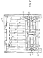
- FIG. 1 an isometric view of the principal components for the six-degrees-of-freedom adjustment assembly used in an ink jet printer is illustrated.
- a catcher/charge plate assembly 10 is fixed in an alignment stand by a V-groove 12 in the catcher/charge plate assembly 10.
- This assembly 10 provides charging and collecting means for controlling droplet streams generated by a droplet generator assembly 14.
- the catcher/charge plate assembly 10 incorporates a fixed rear frame 16 which provides a spring bias at location 18 against a removable first adjustment frame 20, which allows for physical adjustments.
- the rear frame 16, also designated the second frame provides a spring bias for the physical adjustments, and further provides a clamp force.
- the drop generator assembly 14, then, is situated between the first frame 20 and the second frame 16.
- a top view which demonstrates the principle adjustments between the catcher/charge plate assembly 10 and the droplet generator assembly 14 is shown.
- the spring bias at location 18 provides compressive force on the droplet generator assembly 14 against precision adjustment screws 22, preferably 120 tpi.
- This coupling provides a method for moving the droplet array generated by the droplet generator assembly 14 toward and away from the charge lead array, thereby providing the third degree of freedom of translation for the mounting and alignment apparatus of the present invention.
- the third degree of freedom of translation comprises a reciprocal adjustment for moving the plurality of jets relative to the plurality of charge leads.
- This coupling also allows an operator to rotate the droplet generator assembly 14 array until it is parallel to the face of the catcher/charge plate assembly 10 lead array, thereby providing for the second degree of freedom of rotation, which comprises a second parallel adjustment for aligning the array of orifices parallel to the charge plate face.
- a similar spring bias and screw combination is accomplished with the spring 23 and the screw 24.
- This portion of the assembly of the present invention provides a translation means for positioning each of the plurality of droplets relative to the plurality of charge leads.
- This portion of the assembly, along with a member 25 for translation, provide the second degree of freedom of translation.
- the second degree of freedom of translation comprises an alignment adjustment for aligning each of the plurality of jets with respect to each of the plurality of charge leads.
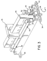
- the droplet generator assembly 14 comprises a drop generator 26 with dowel pins 28 used to mount into a lower frame 30. Clamp bars 32 are used to fix the drop generator 26 to the lower frame 30.
- the lower frame 30 couples to a first base support 34 and a second base support 36. The bottom surfaces of the base supports 34 and 36 rest directly on the catcher/charge plate assembly 10 of Figs. 1 and 2.
- the height of the resonator 26, the parallelism for aligning the plurality of jets relative to the charge plate face, the parallelism for aligning the orifice plate parallel to the top of the charge leads, and the rotation or the plurality of jets about the x-axis indicated by rotation arrow 38, are obtained by adjusting precision screws 40, best illustrated in Fig. 2.
- the height adjustment of the resonator 26 relative to the charge plate of assembly 10 provides the first degree of freedom of translation.
- the first parallel adjustment for aligning the plurality of jets parallel to the charge plate face provides the first degree of freedom of rotation.
- the third parallel adjustment for aligning the orifice plate parallel to the top of the charge leads provides the third degree of freedom of rotation.
- the drop generator 26 is locked into place using set screws 42, and corresponding screws (not shown) on the opposing side of the frame 30.
- the lower frame 30 is a second permanent frame and provides the spring bias for critical alignment parameters.
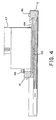
- the lower frame 30 also constrains a compression member 44 which is attached to a low durometer compressive material 45 which provides a clamping force on cables from charge driver boards 47.
- the cables provide charging signals to the plurality of charge leads fixed to the catcher assembly 10.
- the compression member 44 is constrained from motion by affixing the compression member 44 to the catcher assembly 10 at location 46, and fixing the lower frame 30 to the catcher assembly 10 at location 48.
- the mounting and alignment apparatus according to the present invention is useful in continuous ink jet printers.
- the mounting and alignment apparatus of the present invention provides for adjustment by height and tilt of the resonator structure to precisely control the tilt of the resonator relative to the charge plate, thereby providing consistent print windows.
- the present invention provides the further advantage of allowing height changes to accommodate a wider range of charge plate flatness co-planarity.
- the present invention provides the advantage of easily compensating for changes in ink which may have difficult filament break-off centers.
Applications Claiming Priority (2)
| Application Number | Priority Date | Filing Date | Title |
|---|---|---|---|
| US891342 | 1992-05-29 | ||
| US07/891,342 US5475409A (en) | 1992-05-29 | 1992-05-29 | Alignment structure for components of an ink jet print head |
Publications (3)
| Publication Number | Publication Date |
|---|---|
| EP0571786A2 true EP0571786A2 (fr) | 1993-12-01 |
| EP0571786A3 EP0571786A3 (fr) | 1995-05-03 |
| EP0571786B1 EP0571786B1 (fr) | 2000-06-28 |
Family
ID=25398020
Family Applications (1)
| Application Number | Title | Priority Date | Filing Date |
|---|---|---|---|
| EP93107151A Expired - Lifetime EP0571786B1 (fr) | 1992-05-29 | 1993-05-03 | Imprimante par jet d'encre en continu avec dispositif d'alignement pour les éléments de la tête d'impression |
Country Status (4)
| Country | Link |
|---|---|
| US (1) | US5475409A (fr) |
| EP (1) | EP0571786B1 (fr) |
| JP (1) | JP3510288B2 (fr) |
| DE (1) | DE69328915T2 (fr) |
Cited By (5)
| Publication number | Priority date | Publication date | Assignee | Title |
|---|---|---|---|---|
| EP0791460A2 (fr) * | 1996-02-23 | 1997-08-27 | SCITEX DIGITAL PRINTING, Inc. | Blocage en position instantanné d'un résonateur |
| EP0791461A2 (fr) * | 1996-02-23 | 1997-08-27 | SCITEX DIGITAL PRINTING, Inc. | Ensemble de montage à faibles contraintes pour générateur de gouttelettes |
| WO1998028152A1 (fr) * | 1996-12-23 | 1998-07-02 | Domino Printing Sciences Plc | Dispositif de flexion pour imprimante a jet d'encre continu |
| CN102175880A (zh) * | 2011-01-14 | 2011-09-07 | 郝玉有 | 多孔板取样高度调节器 |
| CN113478196A (zh) * | 2021-07-07 | 2021-10-08 | 湖北增江建设工程有限公司 | 一种彩钢板拼接安装方法 |
Families Citing this family (20)
| Publication number | Priority date | Publication date | Assignee | Title |
|---|---|---|---|---|
| DE69616814T2 (de) | 1995-06-12 | 2002-05-29 | Citizen Watch Co Ltd | Verfahren zur herstellung eines tintenstrahlkopfes und spannvorrichtung zur herstellung des tintenstrahlkopfes |
| US6113231A (en) * | 1998-02-25 | 2000-09-05 | Xerox Corporation | Phase change ink printing architecture suitable for high speed imaging |
| US6213580B1 (en) | 1998-02-25 | 2001-04-10 | Xerox Corporation | Apparatus and method for automatically aligning print heads |
| US6270204B1 (en) | 1998-03-13 | 2001-08-07 | Iris Graphics, Inc. | Ink pen assembly |
| DE69910340T2 (de) | 1998-12-14 | 2004-07-01 | Scitex Digital Printing, Inc., Dayton | Monolithisches Tintenstrahldruckchassis |
| DE69931880T2 (de) | 1998-12-14 | 2007-05-31 | Eastman Kodak Co. | Elektrische Verdrahtung hoher Dichte für einen kontinuierlich arbeitenden Tintenstrahldruckkopf |
| US6217162B1 (en) | 1998-12-14 | 2001-04-17 | Scitex Digital Printing, Inc. | Alignment apparatus for an ink jet droplet generator |
| WO2005123392A1 (fr) * | 2004-06-17 | 2005-12-29 | Videojet Technologies Inc. | Systeme pour aligner un tunnel de charge d'une imprimante a jet d'encre |
| US7399068B2 (en) * | 2005-03-04 | 2008-07-15 | Eastman Kodak Company | Continuous ink jet printing apparatus with integral deflector and gutter structure |
| US7540589B2 (en) * | 2006-05-11 | 2009-06-02 | Eastman Kodak Company | Integrated charge and orifice plates for continuous ink jet printers |
| US7437820B2 (en) * | 2006-05-11 | 2008-10-21 | Eastman Kodak Company | Method of manufacturing a charge plate and orifice plate for continuous ink jet printers |
| US7552534B2 (en) * | 2006-05-11 | 2009-06-30 | Eastman Kodak Company | Method of manufacturing an integrated orifice plate and electroformed charge plate |
| US7568285B2 (en) * | 2006-05-11 | 2009-08-04 | Eastman Kodak Company | Method of fabricating a self-aligned print head |
| US7758155B2 (en) * | 2007-05-15 | 2010-07-20 | Eastman Kodak Company | Monolithic printhead with multiple rows of inkjet orifices |
| US20080284835A1 (en) * | 2007-05-15 | 2008-11-20 | Panchawagh Hrishikesh V | Integral, micromachined gutter for inkjet printhead |
| US20090027460A1 (en) * | 2007-07-23 | 2009-01-29 | Paul Klinker | System for aligning a charge tunnel of an ink jet printer |
| US20090033727A1 (en) * | 2007-07-31 | 2009-02-05 | Anagnostopoulos Constantine N | Lateral flow device printhead with internal gutter |
| US8585179B2 (en) * | 2008-03-28 | 2013-11-19 | Eastman Kodak Company | Fluid flow in microfluidic devices |
| KR20110069360A (ko) * | 2009-12-17 | 2011-06-23 | 삼성전기주식회사 | 잉크젯 프린트 헤드, 잉크젯 프린트 헤드 어셈블리 및 잉크젯 프린트 헤드 어셈블리의 제조방법 |
| JP7262276B2 (ja) | 2019-03-29 | 2023-04-21 | ミネベアミツミ株式会社 | アブソリュートエンコーダ |
Citations (6)
| Publication number | Priority date | Publication date | Assignee | Title |
|---|---|---|---|---|
| US4277790A (en) * | 1979-12-26 | 1981-07-07 | International Business Machines Corporation | Field replaceable modules for ink jet head assembly |
| US4338610A (en) * | 1972-11-21 | 1982-07-06 | Burroughs Corporation | Modular-head endorser |
| US4356499A (en) * | 1979-11-28 | 1982-10-26 | Ricoh Co., Ltd. | Ink-jet recording device |
| US4520367A (en) * | 1983-04-11 | 1985-05-28 | Ricoh Company, Ltd. | Ink jet head assembly |
| US4743922A (en) * | 1984-11-13 | 1988-05-10 | Imaje S.A. | Ink jet single-nozzle printing head |
| US4800398A (en) * | 1986-11-14 | 1989-01-24 | Ricoh Company, Ltd. | Ink-jet printer with an encased printer head unit |
Family Cites Families (5)
| Publication number | Priority date | Publication date | Assignee | Title |
|---|---|---|---|---|
| US4080607A (en) * | 1976-07-12 | 1978-03-21 | The Mead Corporation | Jet drop printing head and assembly method therefor |
| JPS5869057A (ja) * | 1981-10-20 | 1983-04-25 | Ricoh Co Ltd | インクシエツトプリンタのキヤリツジ装置 |
| US4550320A (en) * | 1983-10-31 | 1985-10-29 | Centronics Data Computer Corp. | Carriage-mounted velocity multi-deflection compensation for bi-directional ink jet printers |
| US4879565A (en) * | 1988-01-27 | 1989-11-07 | Minolta Camera Kabushiki Kaisha | Ink jet printer |
| US5115251A (en) * | 1990-08-17 | 1992-05-19 | Elmjet Limited | Continuous ink jet printing device |
-
1992
- 1992-05-29 US US07/891,342 patent/US5475409A/en not_active Expired - Lifetime
-
1993
- 1993-05-03 DE DE69328915T patent/DE69328915T2/de not_active Expired - Lifetime
- 1993-05-03 EP EP93107151A patent/EP0571786B1/fr not_active Expired - Lifetime
- 1993-05-31 JP JP12963393A patent/JP3510288B2/ja not_active Expired - Lifetime
Patent Citations (6)
| Publication number | Priority date | Publication date | Assignee | Title |
|---|---|---|---|---|
| US4338610A (en) * | 1972-11-21 | 1982-07-06 | Burroughs Corporation | Modular-head endorser |
| US4356499A (en) * | 1979-11-28 | 1982-10-26 | Ricoh Co., Ltd. | Ink-jet recording device |
| US4277790A (en) * | 1979-12-26 | 1981-07-07 | International Business Machines Corporation | Field replaceable modules for ink jet head assembly |
| US4520367A (en) * | 1983-04-11 | 1985-05-28 | Ricoh Company, Ltd. | Ink jet head assembly |
| US4743922A (en) * | 1984-11-13 | 1988-05-10 | Imaje S.A. | Ink jet single-nozzle printing head |
| US4800398A (en) * | 1986-11-14 | 1989-01-24 | Ricoh Company, Ltd. | Ink-jet printer with an encased printer head unit |
Cited By (9)
| Publication number | Priority date | Publication date | Assignee | Title |
|---|---|---|---|---|
| EP0791460A2 (fr) * | 1996-02-23 | 1997-08-27 | SCITEX DIGITAL PRINTING, Inc. | Blocage en position instantanné d'un résonateur |
| EP0791461A2 (fr) * | 1996-02-23 | 1997-08-27 | SCITEX DIGITAL PRINTING, Inc. | Ensemble de montage à faibles contraintes pour générateur de gouttelettes |
| EP0791461A3 (fr) * | 1996-02-23 | 1998-04-29 | SCITEX DIGITAL PRINTING, Inc. | Ensemble de montage à faibles contraintes pour générateur de gouttelettes |
| EP0791460A3 (fr) * | 1996-02-23 | 1998-04-29 | SCITEX DIGITAL PRINTING, Inc. | Blocage en position instantanné d'un résonateur |
| WO1998028152A1 (fr) * | 1996-12-23 | 1998-07-02 | Domino Printing Sciences Plc | Dispositif de flexion pour imprimante a jet d'encre continu |
| CN102175880A (zh) * | 2011-01-14 | 2011-09-07 | 郝玉有 | 多孔板取样高度调节器 |
| CN102175880B (zh) * | 2011-01-14 | 2012-12-26 | 郝玉有 | 多孔板取样高度调节器 |
| CN113478196A (zh) * | 2021-07-07 | 2021-10-08 | 湖北增江建设工程有限公司 | 一种彩钢板拼接安装方法 |
| CN113478196B (zh) * | 2021-07-07 | 2022-11-08 | 深圳市海龙绿建科技有限公司 | 一种彩钢板拼接安装方法 |
Also Published As
| Publication number | Publication date |
|---|---|
| DE69328915D1 (de) | 2000-08-03 |
| US5475409A (en) | 1995-12-12 |
| JPH0631925A (ja) | 1994-02-08 |
| EP0571786B1 (fr) | 2000-06-28 |
| JP3510288B2 (ja) | 2004-03-22 |
| EP0571786A3 (fr) | 1995-05-03 |
| DE69328915T2 (de) | 2000-12-07 |
Similar Documents
| Publication | Publication Date | Title |
|---|---|---|
| US5475409A (en) | Alignment structure for components of an ink jet print head | |
| US6471335B1 (en) | Method for mutual spatial registration of inkjet cartridges | |
| KR101224011B1 (ko) | 드롭렛 방출 장치 정렬 | |
| US7819501B2 (en) | Jetting module installation and alignment apparatus | |
| JP6524173B2 (ja) | 流体吐出モジュール装着 | |
| CA2301864C (fr) | Procede de fabrication d'un appareil d'impression | |
| JPH0261395B2 (fr) | ||
| JP2000190465A (ja) | インクジェット式記録ヘッドの取付構造及びインクジェット式記録ヘッドの固定方法 | |
| EP0791461B1 (fr) | Ensemble de montage à faibles contraintes pour générateur de gouttelettes | |
| EP0791460B1 (fr) | Blocage en position instantanné d'un résonateur | |
| JP5125018B2 (ja) | ヘッドユニットの製造方法および製造装置 | |
| US20240095940A1 (en) | Liquid ejection head and liquid ejection apparatus including the same | |
| JP4797259B2 (ja) | インクジェットプリントヘッドの製造方法及びインクジェットプリントヘッド並びにインクジェット記録装置 | |
| JP2958928B2 (ja) | 長尺サーマルヘッドと高さ調整用治具 |
Legal Events
| Date | Code | Title | Description |
|---|---|---|---|
| PUAI | Public reference made under article 153(3) epc to a published international application that has entered the european phase |
Free format text: ORIGINAL CODE: 0009012 |
|
| AK | Designated contracting states |
Kind code of ref document: A2 Designated state(s): DE FR GB |
|
| RAP1 | Party data changed (applicant data changed or rights of an application transferred) |
Owner name: SCITEX DIGITAL PRINTING, INC. (A MASSACHUSETTS COR |
|
| 17P | Request for examination filed |
Effective date: 19940727 |
|
| PUAL | Search report despatched |
Free format text: ORIGINAL CODE: 0009013 |
|
| AK | Designated contracting states |
Kind code of ref document: A3 Designated state(s): DE FR GB |
|
| 17Q | First examination report despatched |
Effective date: 19961104 |
|
| RTI1 | Title (correction) |
Free format text: CONTINUOUS INK JET PRINTER HAVING AN ALIGNMENT APPARATUS FOR THE COMPONENTS OF THE PRINT HEAD |
|
| GRAG | Despatch of communication of intention to grant |
Free format text: ORIGINAL CODE: EPIDOS AGRA |
|
| RTI1 | Title (correction) |
Free format text: CONTINUOUS INK JET PRINTER HAVING AN ALIGNMENT APPARATUS FOR THE COMPONENTS OF THE PRINT HEAD |
|
| GRAG | Despatch of communication of intention to grant |
Free format text: ORIGINAL CODE: EPIDOS AGRA |
|
| GRAH | Despatch of communication of intention to grant a patent |
Free format text: ORIGINAL CODE: EPIDOS IGRA |
|
| GRAH | Despatch of communication of intention to grant a patent |
Free format text: ORIGINAL CODE: EPIDOS IGRA |
|
| GRAA | (expected) grant |
Free format text: ORIGINAL CODE: 0009210 |
|
| AK | Designated contracting states |
Kind code of ref document: B1 Designated state(s): DE FR GB |
|
| REF | Corresponds to: |
Ref document number: 69328915 Country of ref document: DE Date of ref document: 20000803 |
|
| ET | Fr: translation filed | ||
| PLBE | No opposition filed within time limit |
Free format text: ORIGINAL CODE: 0009261 |
|
| STAA | Information on the status of an ep patent application or granted ep patent |
Free format text: STATUS: NO OPPOSITION FILED WITHIN TIME LIMIT |
|
| 26N | No opposition filed | ||
| REG | Reference to a national code |
Ref country code: GB Ref legal event code: IF02 |
|
| REG | Reference to a national code |
Ref country code: GB Ref legal event code: 732E |
|
| REG | Reference to a national code |
Ref country code: FR Ref legal event code: TP |
|
| PGFP | Annual fee paid to national office [announced via postgrant information from national office to epo] |
Ref country code: GB Payment date: 20050406 Year of fee payment: 13 |
|
| PGFP | Annual fee paid to national office [announced via postgrant information from national office to epo] |
Ref country code: FR Payment date: 20050517 Year of fee payment: 13 |
|
| PGFP | Annual fee paid to national office [announced via postgrant information from national office to epo] |
Ref country code: DE Payment date: 20050531 Year of fee payment: 13 |
|
| PG25 | Lapsed in a contracting state [announced via postgrant information from national office to epo] |
Ref country code: DE Free format text: LAPSE BECAUSE OF THE APPLICANT RENOUNCES Effective date: 20060221 |
|
| PG25 | Lapsed in a contracting state [announced via postgrant information from national office to epo] |
Ref country code: GB Free format text: LAPSE BECAUSE OF NON-PAYMENT OF DUE FEES Effective date: 20060503 |
|
| GBPC | Gb: european patent ceased through non-payment of renewal fee |
Effective date: 20060503 |
|
| REG | Reference to a national code |
Ref country code: FR Ref legal event code: ST Effective date: 20070131 |
|
| PG25 | Lapsed in a contracting state [announced via postgrant information from national office to epo] |
Ref country code: FR Free format text: LAPSE BECAUSE OF NON-PAYMENT OF DUE FEES Effective date: 20060531 |