EP0571637A1 - Rotary engine - Google Patents
Rotary engine Download PDFInfo
- Publication number
- EP0571637A1 EP0571637A1 EP92924894A EP92924894A EP0571637A1 EP 0571637 A1 EP0571637 A1 EP 0571637A1 EP 92924894 A EP92924894 A EP 92924894A EP 92924894 A EP92924894 A EP 92924894A EP 0571637 A1 EP0571637 A1 EP 0571637A1
- Authority
- EP
- European Patent Office
- Prior art keywords
- side seal
- housing
- rotary engine
- rotor
- linear
- Prior art date
- Legal status (The legal status is an assumption and is not a legal conclusion. Google has not performed a legal analysis and makes no representation as to the accuracy of the status listed.)
- Ceased
Links
Images


Classifications
-
- F—MECHANICAL ENGINEERING; LIGHTING; HEATING; WEAPONS; BLASTING
- F02—COMBUSTION ENGINES; HOT-GAS OR COMBUSTION-PRODUCT ENGINE PLANTS
- F02B—INTERNAL-COMBUSTION PISTON ENGINES; COMBUSTION ENGINES IN GENERAL
- F02B55/00—Internal-combustion aspects of rotary pistons; Outer members for co-operation with rotary pistons
- F02B55/02—Pistons
-
- F—MECHANICAL ENGINEERING; LIGHTING; HEATING; WEAPONS; BLASTING
- F01—MACHINES OR ENGINES IN GENERAL; ENGINE PLANTS IN GENERAL; STEAM ENGINES
- F01C—ROTARY-PISTON OR OSCILLATING-PISTON MACHINES OR ENGINES
- F01C19/00—Sealing arrangements in rotary-piston machines or engines
- F01C19/08—Axially-movable sealings for working fluids
-
- Y—GENERAL TAGGING OF NEW TECHNOLOGICAL DEVELOPMENTS; GENERAL TAGGING OF CROSS-SECTIONAL TECHNOLOGIES SPANNING OVER SEVERAL SECTIONS OF THE IPC; TECHNICAL SUBJECTS COVERED BY FORMER USPC CROSS-REFERENCE ART COLLECTIONS [XRACs] AND DIGESTS
- Y02—TECHNOLOGIES OR APPLICATIONS FOR MITIGATION OR ADAPTATION AGAINST CLIMATE CHANGE
- Y02T—CLIMATE CHANGE MITIGATION TECHNOLOGIES RELATED TO TRANSPORTATION
- Y02T10/00—Road transport of goods or passengers
- Y02T10/10—Internal combustion engine [ICE] based vehicles
- Y02T10/12—Improving ICE efficiencies
Definitions
- the present invention relates to an internal combustion engine, and more particularly to a rotary engine.
- a rotary engine used in an automobile or the like comprises a rotor housing; a side housing and an intermediate housing arranged in such a manner as to sandwich the rotor housing from both sides thereof; a rotor accommodated rotatably in the rotor housing; side seal grooves formed respectively on both side surfaces of the rotor facing the side housing and the intermediate housing; side seals accommodated respectively in the side seal grooves; and apex seals disposed at apexes of the rotor.
- end faces thereof at positions projecting from the side seal grooves are urged toward and are made to slidably abut against the side housing and the intermediate housing that face the end faces, respectively, by means of springs accommodated in the side seal grooves, thereby attaining primary gastightness with respect to an engine operating chamber.
- the rotor axis-side side surfaces of the side seals are urged toward and are made to slidably abut against side wall surfaces of the side seal grooves facing those respective side surfaces by means of gas pressure and the like, thereby attaining secondary gastightness with respect to the engine operating chamber.
- each side seal has a long length, and distances from the rotor center to respective positions thereof differ, the magnitudes and directions of sliding resistance and inertial force at the respective positions thereof differ respectively. For this reason, each side seal abuts against the side wall surface of the side seal groove in an unnatural posture.
- the frictional resistance of contact between the side seal and the side wall surface of the side seal groove is large (which is considered to be 0.1 to 0.3 in terms of a coefficient of friction), and even if the side seal is subjected to a lifting force by the gas pressure inside the side seal groove when the side seal is pressed against the side wall surface of the side seal groove by the gas pressure from the engine operating chamber, the behavior of the side seal is poor, and the sliding contact of the side seal with respect to the side housing is not established sufficiently. For this reason, high-temperature gases burst out from the gap between the side seal and the side housing, thereby resulting in the overheating of the rotary engine and causing damage to a rotor oil seal. This overheating of the rotary engine causes deformation of the rotary engine, i.e., deformation of the side housing, thereby resulting in a vicious circle of bringing about further gas leakage.
- combustion gases leaking from the side seal circulate to the intake side and are sucked in by being mixed with a fresh intake gas, thereby constituting a cause of misfiring and resulting in a decline in output.
- the present invention has been devised in view of the above-described aspects, and its object is to provide a rotary engine which increases the mobility of each side seal in the side seal groove toward the sliding surfaces of the side housing and the intermediate housing so as to prevent a gap from being formed between an end face of the side seal and the respective sliding surfaces of the side housing and the intermediate housing, thereby making it possible to attain primary gastightness more reliably without deteriorating secondary gastightness.
- a rotary engine comprising: a rotor housing; a side housing and an intermediate housing arranged in such a manner as to sandwich the rotor housing from both sides thereof; a rotor accommodated rotatably in the rotor housing; a side seal groove formed on each of both side surfaces of the rotor facing the side housing and the intermediate housing; side seals each accommodated in the side seal groove; springs for pressing the side seals against the side housing and the intermediate housing, respectively; and a linear roller accommodated along the side seal between a side wall surface of the side seal groove and the side seal.
- a rotary engine comprising: a side housing; a rotor housing; a rotor accommodated rotatably in the rotor housing; a side seal groove formed on a side surface of the rotor facing the side housing; a side seal accommodated in the side seal groove; a spring for urging the side seal against the side housing; and at least one linear roller accommodated between a side wall surface of the side seal groove and the side seal along the side seal.
- a groove is formed on a rotor axis-side side surface of the side seal, and the linear roller is accommodated in the groove.
- a stepped portion is formed on a rotor axis-side side surface of the side seal, and the linear roller is accommodated in a recess of the stepped portion.
- a thin steel sheet against which the linear roller abuts may be attached on a side wall surface of the side seal groove facing a rotor axis-side side surface of the side seal.
- a groove for accommodating the linear roller may be formed in this thin steel sheet.
- one linear roller may be used, but a plurality of linear rollers may be arranged in parallel, or a plurality of linear rollers may be arranged in series. In a case where a plurality of linear rollers are arranged in parallel and in series, if positions of opposing ends of the linear rollers in adjacent two rows of the linear rollers are made mutually different, it is possible to prevent a decline in gastightness.
- the side seal accommodated in the side seal is urged by the spring, and its end face is brought into slidable contact with the side housing.
- the side seal behaves lightly and speedily through linear contact or rolling contact between the linear roller and the side seal groove, so that the sliding contact of the side seal with respect to the sliding surfaces of the side housing and the intermediate housing is effected reliably, thereby securing sufficient gastightness.
- the sliding contact of the side seal with respect to the sliding surfaces of the side housing and the intermediate housing is improved, it is possible to reliably prevent leakage of combustion gases and the like, primary gastightness can be maintained reliably, the overheating of the engine, misfiring and the like can be prevented, and the output can be improved.
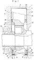
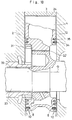
- a rotary engine 1 of this embodiment comprises a side housing 2; an intermediate housing 12; a rotor housing 3; a rotor 4 accommodated rotatably in the rotor housing 3; arcuate side seal grooves 6 formed on both side surfaces 5 and 25 of the rotor 4 which are respectively arranged in face-to-face relation with the side housing 2 and the intermediate housing 12; side seals 7 accommodated respectively in the side seal grooves 6; springs 8 for urging the side seals 7 toward the side housing 2 and the intermediate housing 12, respectively; and at least one flexible linear roller 10 disposed between a side wall surface 9 in the side seal groove 6 and the side seal 7 and accommodated along the side seal 7, three flexible linear rollers 10 being provided in parallel in this embodiment.
- the side housing 2 and the intermediate housing 12 are disposed in such a manner as to sandwich the rotor housing 3 from both sides thereof.
- side seal grooves 6, the side seals 7, and the like are formed in substantially the same manner on both the side housing 2 side and the intermediate housing 12 side.
- a detailed description will be given of the side housing 2 side, and the intermediate housing 12 side will be illustrated in the drawings.
- a groove 21 is formed on a rotor axis O-side side surface of each side seal 7 in this embodiment, and the three linear rollers 10 are accommodated in the groove 21 of each side seal 7.
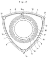
- the rotor 4 is mounted on an eccentric shaft 23 via a rotor bearing 22, and an apex seal 24 which slidably abuts against the inner surface of the rotor housing 3 is disposed at each apex of the rotor 4.
- the side seal grooves 6 extend to the vicinity of each apex seal 24, and three apex seals are provided on the side surface 5 of the rotor 4, and the side seal 7 is accommodated in each of the sides seal grooves 6 (the same arrangement is adopted for the other side 25 of the rotor 4 opposite to the side surface 5).
- the linear roller 10 accommodated in the groove 21 in each side seal 7 has a circular cross-sectional configuration, and three linear rollers 10 are provided in this embodiment as described above.
- the present invention is not restricted to the same, and one, two, or four or more linear rollers 10 may be used.
- the linear roller 10 in this embodiment is formed of a steel wire made of steel, stainless steel, bearing steel, or the like, but it may be formed of other material.
- the diameter of the linear roller 10 is selected from the range of 0.2 mm to 1.0 mm, preferably 0.2 mm to 0.5 mm.
- an internal gear 31 is attached to the rotor 4, the internal gear 31 meshes with a fixed external gear 32, a main bearing 33 is fitted over the eccentric shaft 23, and oil seal devices 36 and 37 are respectively fitted in two annular grooves 34 and 35 provided on the side surfaces 5 and 25 of the rotor 4.
- an end face 41 of the side seal 7 projecting from the side seal groove 6 slidably abuts against the side housing 2 by being urged by the spring 8 accommodated in the side seal groove 6, thereby attaining primary gastightness with respect to an engine operating chamber.
- the linear rollers 10 in the recess 21 formed on the axis O-side side surface of the side seal 7 are urged against the side wall surface 9 of the side seal groove 6 facing that side surface by means of the gas pressure and the like of the engine operating chamber, thereby attaining secondary gastightness with respect to an engine operating chamber.
- the linear rollers 10 abut against the side wall surface 9, even if the side seal 7 undergoes a very small displacement in the direction of A inside the side seal groove 6 for some reason or other, the side seal 7 is readily restored to its original state through the rotation of the linear rollers 10 or through the rolling friction or low sliding friction due to the linear contact of the linear rollers 10 against the side wall surface 9, thereby always maintaining the primary gastightness reliably.
- the spring 8 is capable of causing the end face 41 of the side seal 7 to abut against the side housing 2 slidably and with desired gastightness. Accordingly, in the rotary engine 1, it is possible to reliably prevent the leakage of gases from the engine operating chamber, with the result that the engine efficiency can be enhanced.
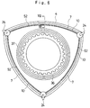
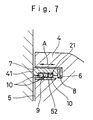
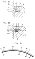
- a rotary engine 51 may be formed, as shown in Figs. 5 to 7. That is, in the rotary engine 51, a thin steel sheet 52 against which the linear rollers 10 abut are secured on the side wall surface 9 of the side seal groove 6 facing the axis O-side position of the side seal 7. If the linear rollers 10 are made to abut against the thin steel sheet 52 in this manner, the linear rollers 10 are prevented from coming into direct contact with the side wall surface 9 of the side seal groove 6, so that it is possible to prevent damage, such as indents, from being caused to the side wall surface 9 by the linear rollers 10. As a result, the return of the side seal 7 to its original position in the direction of A can be effected more favorably.
- the thickness of the thin steel sheet for example, it is possible to 0.05 mm to 0.3 mm, preferably 0.05 mm to 0.1 mm.
- the thin steel plate 52 is formed of a material such as the stainless steel similar to that of the linear roller 10.
- the linear rollers 10 may be divided and disposed in parallel. That is, as shown in Fig. 8, a plurality of rows, e.g. three rows as in the above-described example, of a plurality of, i.e., in this example two, linear rollers 62 and 63 fitted in series with respective ends facing each other at a position 61 are arranged in the groove 21 of the side seal 7, thereby forming the rotary engine. If the plurality of linear rollers are arranged in series in the groove 21 of each side seal 7, the rotation of the respective linear rollers is facilitated, whereby the return of the side seal 7 to its original position in the direction of A can also be effected more favorably.
- a plurality of rows e.g. three rows as in the above-described example, of a plurality of, i.e., in this example two, linear rollers 62 and 63 fitted in series with respective ends facing each other at a position 61 are arranged in the groove 21 of the side seal 7, thereby forming the
- an arrangement may be provided such that, by using a side seal 65 having a stepped portion 66 formed thereof, the linear rollers 10 are arranged in a recess 67 of the stepped portion 66, thereby forming the rotary engine.
- four linear rollers 10 are accommodated between the stepped portion 66 and the spring 8, and the four linear rollers 10 are maintained in the direction of A by means of the stepped portion 66 and the spring 8.
- linear rollers 10 Although in the foregoing examples, three or four linear rollers 10 are provided, as shown in Figs. 10 and 11, two linear rollers 10 may be arranged in the groove 21 of the side seal 7, thereby forming the rotary engine.
- an arrangement may be provided as follows: A plate-like side seal 71 not having a groove is disposed in the side seal groove 6, a groove 74 for accommodating the linear rollers 10 is formed in a thin steel sheet 73 secured to the side wall surface 9 of the side seal groove 6, the linear rollers 10 are held in the groove 74 of the thin steel sheet 73 in such a manner that the linear rollers 10 do not move in the direction of A but the linear rollers 10 themselves are rotatable, an end face 72 of the side seal 71 is made to abut against the side housing 2 by means of the spring 8, thereby forming the rotary engine of the present invention.
- an arrangement may be provided as follows: Linear rollers 81, 82, 84, 85, 87, and 88 of mutually different lengths are prepared, the linear rollers 81 and 82, the linear rollers 84 and 85, and the linear rollers 87 and 88 are arranged in series, respectively, and these three rows are juxtaposed in the groove of the side seal 7, such that a position 83 of opposing ends of the linear rollers 81 and 82 and a position 86 of opposing ends of the linear rollers 84 and 85, as well as the position 86 of the opposing ends in the row of the linear rollers 84 and 85 and a position 89 of opposing ends in the row of the linear rollers 87 and 88, are made to be mutually different.
- the positions of opposing ends in the two adjacent rows of linear rollers are made to be mutually different, it is possible to further reduce the leakage of gasses from the engine operating chamber which pass through gaps between the opposing ends. It should be noted that the positions of the ends are not restricted to those of this example, and it suffices if the positions are set to optimum positions in the light of reducing the gas leakage to a minimum.
Landscapes
- Engineering & Computer Science (AREA)
- Mechanical Engineering (AREA)
- General Engineering & Computer Science (AREA)
- Chemical & Material Sciences (AREA)
- Combustion & Propulsion (AREA)
- Sealing Devices (AREA)
Applications Claiming Priority (4)
| Application Number | Priority Date | Filing Date | Title |
|---|---|---|---|
| JP352051/91 | 1991-12-13 | ||
| JP35205191 | 1991-12-13 | ||
| JP194759/92 | 1992-06-29 | ||
| JP4194759A JPH0788780B2 (ja) | 1991-12-13 | 1992-06-29 | ロータリエンジン |
Publications (2)
| Publication Number | Publication Date |
|---|---|
| EP0571637A1 true EP0571637A1 (en) | 1993-12-01 |
| EP0571637A4 EP0571637A4 (enExample) | 1994-03-30 |
Family
ID=26508717
Family Applications (1)
| Application Number | Title | Priority Date | Filing Date |
|---|---|---|---|
| EP92924894A Ceased EP0571637A1 (en) | 1991-12-13 | 1992-12-09 | Rotary engine |
Country Status (4)
| Country | Link |
|---|---|
| US (1) | US5397224A (enExample) |
| EP (1) | EP0571637A1 (enExample) |
| JP (1) | JPH0788780B2 (enExample) |
| WO (1) | WO1993012330A1 (enExample) |
Families Citing this family (7)
| Publication number | Priority date | Publication date | Assignee | Title |
|---|---|---|---|---|
| AU726791B1 (en) * | 2000-05-12 | 2000-11-23 | Peter A. Szorenyi | Hinged rotor internal combustion engine |
| US6659065B1 (en) | 2002-08-12 | 2003-12-09 | David C Renegar | Flexible vane rotary engine |
| GB2464366B (en) * | 2008-10-17 | 2013-01-02 | Ip Consortium Ltd | Seal assembly and method |
| CN102486120A (zh) * | 2009-09-22 | 2012-06-06 | 杨懋钧 | 无死点式稀薄燃烧的转子发动机 |
| DE102011018346B4 (de) | 2011-04-20 | 2012-11-29 | Paul Andreas Woelfle | Rotationskolbenmotor und Abdichtungsverfahren für einen Rotationskolbenmotor |
| US8967988B2 (en) * | 2011-07-28 | 2015-03-03 | Pratt & Whitney Canada Corp. | Apex and face seals with rotary internal combustion engine |
| AU2016228841B2 (en) * | 2015-03-10 | 2020-06-18 | Liquidpiston, Inc. | High power density and efficiency epitrochoidal rotary engine |
Family Cites Families (11)
| Publication number | Priority date | Publication date | Assignee | Title |
|---|---|---|---|---|
| DE1189788B (de) * | 1962-07-24 | 1965-03-25 | Daimler Benz Ag | Radialdichtung fuer Rotationskolben-Brennkraftmaschinen |
| US3765806A (en) * | 1972-03-23 | 1973-10-16 | Audi Ag | Trochoid type of rotary piston combustion engine |
| JPS5069410A (enExample) * | 1973-10-24 | 1975-06-10 | ||
| JPS50123710A (enExample) * | 1974-02-28 | 1975-09-29 | ||
| JPS5341601Y2 (enExample) * | 1974-03-28 | 1978-10-06 | ||
| JPS51136013A (en) * | 1975-05-05 | 1976-11-25 | Caterpillar Tractor Co | Rotary engine |
| JPS5916482Y2 (ja) * | 1977-04-26 | 1984-05-15 | マツダ株式会社 | ロ−タリピストンエンジンのロ−タ構造 |
| JPS5916482A (ja) * | 1982-07-20 | 1984-01-27 | Olympus Optical Co Ltd | 電子ビユ−フアインダ−装置 |
| US4822262A (en) * | 1985-11-19 | 1989-04-18 | Bando Kiko Co., Ltd. | Rotary engine having rollers for the apex seal |
| JPS63147925A (ja) * | 1986-12-09 | 1988-06-20 | Bandou Kiko Kk | アペックスシール部材及び当該アペックスシール部材を備えたロータリエンジン |
| JPH02169823A (ja) * | 1988-12-19 | 1990-06-29 | Bandou Kiko Kk | ロータリーエンジン |
-
1992
- 1992-06-29 JP JP4194759A patent/JPH0788780B2/ja not_active Expired - Lifetime
- 1992-12-09 US US08/087,718 patent/US5397224A/en not_active Expired - Fee Related
- 1992-12-09 EP EP92924894A patent/EP0571637A1/en not_active Ceased
- 1992-12-09 WO PCT/JP1992/001604 patent/WO1993012330A1/ja not_active Ceased
Also Published As
| Publication number | Publication date |
|---|---|
| JPH0788780B2 (ja) | 1995-09-27 |
| EP0571637A4 (enExample) | 1994-03-30 |
| US5397224A (en) | 1995-03-14 |
| JPH05214951A (ja) | 1993-08-24 |
| WO1993012330A1 (fr) | 1993-06-24 |
Similar Documents
| Publication | Publication Date | Title |
|---|---|---|
| US5031922A (en) | Bidirectional finger seal | |
| US3139233A (en) | Seal construction for rotary mechanisms | |
| US5397224A (en) | Elongated roller side seals for a rotary engine | |
| CA1056307A (en) | Oil seal construction for rotary mechanisms | |
| JP2001526366A5 (enExample) | ||
| JPS58163832A (ja) | 一方向クラツチ | |
| US4840600A (en) | Linear needle roller bearing | |
| US4867121A (en) | Piston system for use in an internal combustion engine | |
| US4061445A (en) | Power-converting device | |
| US6139290A (en) | Method to seal a planetary rotor engine | |
| US4319867A (en) | End-face seal for rotary internal-combustion engine | |
| US3261542A (en) | Rotor and seal construction for rotary mechanisms | |
| US4852708A (en) | Spring shield for starter drives for internal combustion engines | |
| JP2002257244A (ja) | 真空ポンプにおける軸封構造 | |
| JP2003322221A (ja) | シールチェーン | |
| US5538409A (en) | Trochoidal piston side seal | |
| JPH0417807Y2 (enExample) | ||
| JPH0129315Y2 (enExample) | ||
| US3802812A (en) | Internal seal for rotary piston combustion engine | |
| JPH0322482Y2 (enExample) | ||
| CA2044842A1 (en) | Multi-piece tilted apex seal assembly | |
| JPH0364601A (ja) | ロータリーエンジン及び該ロータリーエンジン用サイドシール部材 | |
| US3764240A (en) | Side seal assembly for rotary piston mechanisms | |
| JPS5817938Y2 (ja) | 減速・逆転機のクラッチ板中立保持装置 | |
| US3931977A (en) | Seal assembly for rotary mechanisms |
Legal Events
| Date | Code | Title | Description |
|---|---|---|---|
| PUAI | Public reference made under article 153(3) epc to a published international application that has entered the european phase |
Free format text: ORIGINAL CODE: 0009012 |
|
| 17P | Request for examination filed |
Effective date: 19930719 |
|
| AK | Designated contracting states |
Kind code of ref document: A1 Designated state(s): DE ES FR GB IT |
|
| A4 | Supplementary search report drawn up and despatched |
Effective date: 19940209 |
|
| AK | Designated contracting states |
Kind code of ref document: A4 Designated state(s): DE ES FR GB IT |
|
| 17Q | First examination report despatched |
Effective date: 19941130 |
|
| GRAG | Despatch of communication of intention to grant |
Free format text: ORIGINAL CODE: EPIDOS AGRA |
|
| STAA | Information on the status of an ep patent application or granted ep patent |
Free format text: STATUS: THE APPLICATION HAS BEEN REFUSED |
|
| 18R | Application refused |
Effective date: 19961125 |