EP0569959B1 - Schraubenpumpe - Google Patents
Schraubenpumpe Download PDFInfo
- Publication number
- EP0569959B1 EP0569959B1 EP93107722A EP93107722A EP0569959B1 EP 0569959 B1 EP0569959 B1 EP 0569959B1 EP 93107722 A EP93107722 A EP 93107722A EP 93107722 A EP93107722 A EP 93107722A EP 0569959 B1 EP0569959 B1 EP 0569959B1
- Authority
- EP
- European Patent Office
- Prior art keywords
- worm
- track
- housing
- gate members
- pump
- Prior art date
- Legal status (The legal status is an assumption and is not a legal conclusion. Google has not performed a legal analysis and makes no representation as to the accuracy of the status listed.)
- Expired - Lifetime
Links
Images
Classifications
-
- F—MECHANICAL ENGINEERING; LIGHTING; HEATING; WEAPONS; BLASTING
- F04—POSITIVE - DISPLACEMENT MACHINES FOR LIQUIDS; PUMPS FOR LIQUIDS OR ELASTIC FLUIDS
- F04C—ROTARY-PISTON, OR OSCILLATING-PISTON, POSITIVE-DISPLACEMENT MACHINES FOR LIQUIDS; ROTARY-PISTON, OR OSCILLATING-PISTON, POSITIVE-DISPLACEMENT PUMPS
- F04C13/00—Adaptations of machines or pumps for special use, e.g. for extremely high pressures
- F04C13/001—Pumps for particular liquids
- F04C13/002—Pumps for particular liquids for homogeneous viscous liquids
-
- F—MECHANICAL ENGINEERING; LIGHTING; HEATING; WEAPONS; BLASTING
- F04—POSITIVE - DISPLACEMENT MACHINES FOR LIQUIDS; PUMPS FOR LIQUIDS OR ELASTIC FLUIDS
- F04C—ROTARY-PISTON, OR OSCILLATING-PISTON, POSITIVE-DISPLACEMENT MACHINES FOR LIQUIDS; ROTARY-PISTON, OR OSCILLATING-PISTON, POSITIVE-DISPLACEMENT PUMPS
- F04C3/00—Rotary-piston machines or pumps, with non-parallel axes of movement of co-operating members, e.g. of screw type
- F04C3/02—Rotary-piston machines or pumps, with non-parallel axes of movement of co-operating members, e.g. of screw type the axes being arranged at an angle of 90 degrees
- F04C3/04—Rotary-piston machines or pumps, with non-parallel axes of movement of co-operating members, e.g. of screw type the axes being arranged at an angle of 90 degrees of intermeshing engagement type, i.e. with engagement of co-operating members similar to that of toothed gearing
Definitions
- the present invention relates to a worm pump of the kind set forth in the preamble of claim 1.
- Worm pumps of the kind referred to above are known from DE-A-3,408,967.
- the loose gate members 10 are guided in a track housing 5, the latter being capable of pivoting outwards about a pin 14 to allow maintenance work to be done.
- This arrangement makes the gate members 10 accessible for removal, cleaning and/or replacement, but this has to be done through the narrow gap, through which the track housing 5 normally communicates with the tubular worm housing 2.
- internal cleaning of the track housing 5 has to be done through this narrow gap, not being made easier by the presence of a guide wheel 7 for the gate members 10 and its shaft 6.
- the inside of the track housing including the loose gate members lying in the endless track are easily accessible upon opening of the lid or cover.
- the relevant parts of the pump are oriented in the manner set forth in claim 2, ensuring that the loose gate members will not fall out upon opening of the lid or cover.
- GB-A-824,798 describes a pump having many features in common with the pump according to the present invention.
- the features set forth in items a, b, parts of items c-c4 and parts of items d-d2 in claim 1 of the present invention may be found in this pump. There are, however, significant differences:
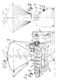
- the stuffing machine shown in the drawing designed for processing meat mass (not shown) or the like, consists in a manner known in principle of two main parts, viz.
- the hopper 1 is provided with a movable cover 3, in the closed position shown fitting closely to the hopper 1, so that the latter may be evacuated by means of known equipment (not shown), e.g. a vacuum pump.
- a supply worm 4 is adapted to rotate about a vertical axis, being supported and driven by a motor assembly 5. The reason for using the term “supply worm” is that it is adapted to supply the meat mass (not shown) being present in the hopper 1 to the worm pump 2, viz. through the latter's inlet 6.
- the worm pump 2 a consists of stationary tubular housing 7, in which the pump's worm 8 is rotatably supported.
- the convolutions 9 of the worm 8 are shaped like a channel having a generally semi-circular shape as seen in a longitudinal sectional view through the worm 8.
- the worm 8 is adapted to be driven counter-clockwise as viewed in Figure 2 by means of a drive assembly 10 consisting of a motor 11 driving a gear box 12, e.g. a planetary gear box, preferably in such a manner that the worm 8 may be driven with different speeds from 0 to 100 rpm. This is based on the worm 8 having a diameter of the order of magnitude 20-30 cm.
- the meat mass having been introduced through the inlet 6 by means of the supply worm 4 will be conveyed to an outlet 13.
- This conveying will, of course, depend on the meat mass not rotating together with the worm 8, as if so, there would not occur any cooperation between the meat mass and the convolutions 9 in the manner known e.g. from small meat mincers, in which the part corresponding to the tubular housing 7 is shaped with longitudinal grooves on the inside.
- the worm pump 2 is additionally provided with a worm gate assembly 14 consisting of a number - in the example shown sixteen - gate members in the form of unconnected disks 15 being guided in an endless track in an elongated track housing 16, viz. between the latter's outer wall and an internal guide 17 situated at a substantially constant distance from the outer wall, with the exception of a rectilinear track portion 18, at which the track housing 16 is in open communication with the inside of the tubular housing 7, the internal guide 17 on this side extending parallel to the worm 8.
- a worm gate assembly 14 consisting of a number - in the example shown sixteen - gate members in the form of unconnected disks 15 being guided in an endless track in an elongated track housing 16, viz. between the latter's outer wall and an internal guide 17 situated at a substantially constant distance from the outer wall, with the exception of a rectilinear track portion 18, at which the track housing 16 is in open communication with the inside of the tubular housing 7, the internal guide 17 on this side extending parallel to the
- the track housing 16 is in the form of a flat tray or pan, closed in a fluid-tight manner by a removable cover 19, so that the endless track, in which the disks 15 are guided, is also delimited by the bottom of the track housing 16 and by the cover 19.
- the gate members in the worm gate assembly 14 are constituted by a number of flat, circular discs 15. It does, however, lie within the scope of the present invention to use gate members of a different shape, provided of course, that they engage in a fluid-tight manner with the convolutions 9 in the worm 8 and can move together with these in the manner described.
- the track housings corresponding to the track housing 16 then, of course, to be shaped in such a manner that they can guide such gate members in the same manner as the track housing 16 guides the disks 15.
- the end of the tubular housing 7 at the greatest distance from the outlet 13 is provided with evacuation means in the form of a vacuum connection 21, being connected to a vacuum pump (not shown) or the like through a "vacuum trap" 22 and a vacuum conduit 23.
- evacuation means in the form of a vacuum connection 21, being connected to a vacuum pump (not shown) or the like through a "vacuum trap" 22 and a vacuum conduit 23.
- the worm pump 2 due to the effect of the disks 15, functions as a volumetric pump, and the formation of air pockets is prevented by means of the vacuum connection 21, the volume of meat mass being conveyed per revolution will be substantially constant, so that the number of revolutions of the worm 8 can be taken as a measure of the volume of the meat mass being ejected through the outlet 13.
- the disks 15 are moved into full engagement with the convolutions 9 on the worm 8 at an appreciable distance from the location, viz. at the inlet 6, where the meat mass first comes into contact with the worm 8.
- This arrangement prevents lumps of meat from getting jammed between one or more of the disks 15 and the convolutions 19, before the disks hav been moved into full engagement with the convolutions 9, and thus, the risk of shearing of meat lumps at this location is avoided.
- the track housing 16 is shaped and oriented in such a manner, that the disks 15 do not fall out upon removal of the cover 19. This is especially an advantage when the disks are to be put back in place after the cleaning, as it would otherwise be necessary to use special leans for holding them in place until the track housing had been closed.
Landscapes
- Engineering & Computer Science (AREA)
- Mechanical Engineering (AREA)
- General Engineering & Computer Science (AREA)
- Rotary Pumps (AREA)
- Processing Of Meat And Fish (AREA)
- Meat, Egg Or Seafood Products (AREA)
- Jellies, Jams, And Syrups (AREA)
Claims (2)
- Schraubenpumps für dicke Medien und/oder Medien, die Klumpen, z.B. Fleisch in Stücken, aufweisen, mit:a) einem in einem Schraubenpumpengehäuse (2) angeordneten, im wesentlichen rotationssymmetrischen rohrförmigen Gehäuse (7) mit einem Einlaß (6) und einem Auslaß (13);b) einem im rohrförmigen Gehäuse (7) drehbar gehaltenen Schraubenrotor (8); undc) einer Schraubengang-Blockiereinrichtung mit:dadurch gekennzeichnet, daßc1) einem seitlich des rohrförmigen Gehäuses (7) angeordneten Führungsbahngehäuse (16), in dem mindestens ein Teil einer endlosen Führungsbahn angeordnet ist, die innen lediglich durch ein von der endlosen Führungsbahn umgebenes Führungselement (17) und außen teilweise von der Innenwand des Führungsbahngehäuses (16) und teilweise vom Schraubenrotor (8) umgeben ist, um Umlaufelemente (15) in der gewünschten Spuranordnung zu halten, undc2) mehreren losen Umlaufelementen (15), die für eine Bewegung entlang der endlosen Führungsbahn gehalten werden, wobei die Umlaufelemente (15) im Abschnitt (18) der endlosen Führüngsbahn, der durch die Innenwand des Führungsbahngehäuses (16) nicht begrenzt ist, mit den Schraubengängen (9) des Schraubenrotors (8) dicht in Eingriff stehen, wobeic3) der Abschnitt (18) der endlosen Führungsbahn sich in mindestens einem Teil seiner Breite, gemessen parallel zur Ebene der endlosen Führungsbahn und quer zur Drehachse des Schraubenrotors (8), außerhalb des Schraubenpumpengehäuses (2) erstreckt, und wobeic4) das Führungsbahngehäuse (16) auf einfache Weise derart geöffnet werden kann, daß die Umlaufelemente (15) quer zur Bewegungsrichtung der losen Umlaufelemente (15) von der endlosen Führungsbahn entfernt und in die endlose Führungsbahn eingesetzt werden können;d) das Führungsbahngehäuse (16) aufweist:(d1) einen tablett- oder pfannenförmigen unteren Abschnitt, an dem das Führungselement (17) befestigt oder zu dem das Führungselement (17) geformt ist, undd2) eine(n) entfernbare(n) Deckel oder Abdeckung (19) zum dichten Abschließen des unteren Abschnitts bezüglich der Umgebung.
- Pumpe nach Anspruch 1, dadurch gekennzeichnet, daßa) die Drehachse des Schraubenrotors (8) sich nicht-vertikal erstreckt undb) das Führungsbahngehäuse (16) derart um die Drehachse ausgerichtet ist, daß die Seite des tablett- oder pfannenförmigen unteren Abschnitts, die durch die entfernbare Abdeckung (19) normalerweise geschlossen ist, schräg nach oben weist.
Applications Claiming Priority (2)
| Application Number | Priority Date | Filing Date | Title |
|---|---|---|---|
| DK636/92 | 1992-05-14 | ||
| DK199200636A DK174039B1 (da) | 1992-05-14 | 1992-05-14 | Sneglpumpe til tyktflydende og/eller klumpholdigemedier, f.eks. kød. |
Publications (2)
| Publication Number | Publication Date |
|---|---|
| EP0569959A1 EP0569959A1 (de) | 1993-11-18 |
| EP0569959B1 true EP0569959B1 (de) | 1997-03-05 |
Family
ID=8095829
Family Applications (1)
| Application Number | Title | Priority Date | Filing Date |
|---|---|---|---|
| EP93107722A Expired - Lifetime EP0569959B1 (de) | 1992-05-14 | 1993-05-12 | Schraubenpumpe |
Country Status (6)
| Country | Link |
|---|---|
| US (1) | US5364251A (de) |
| EP (1) | EP0569959B1 (de) |
| AT (1) | ATE149643T1 (de) |
| DE (1) | DE69308370T2 (de) |
| DK (1) | DK174039B1 (de) |
| ES (1) | ES2098585T3 (de) |
Families Citing this family (8)
| Publication number | Priority date | Publication date | Assignee | Title |
|---|---|---|---|---|
| US6685549B2 (en) * | 2002-05-29 | 2004-02-03 | David F. Henry | Method and device for increasing the shelf life of an oxygen sensitive product |
| EP1829451B1 (de) * | 2006-03-02 | 2008-05-28 | Albert Handtmann Maschinenfabrik GmbH & Co. KG | Füllmaschine und Verfahren zum Zuführen von pastösen Massen aus einem Trichter in ein Förderwerk |
| DE502006002192D1 (de) | 2006-03-09 | 2009-01-08 | Handtmann Albert Maschf | Vorrichtung zur Füllstandsregelung und zur geregelten Evakuierung von pastösen Massen |
| US20070237642A1 (en) * | 2006-04-10 | 2007-10-11 | Murrow Kurt D | Axial flow positive displacement worm pump |
| EP3150072B1 (de) * | 2015-09-29 | 2019-05-15 | Albert Handtmann Maschinenfabrik GmbH & Co. KG | Füllmaschine und verfahren zur füllstandsmessung mit radarsensor, insbesondere bei der wurstherstellung |
| DE102017125668B3 (de) | 2017-11-03 | 2018-10-18 | Ifm Electronic Gmbh | Kugelgewindetrieb mit einstellbarer Vorspannung |
| DE102018129516A1 (de) | 2018-11-23 | 2020-05-28 | Ifm Electronic Gmbh | Kugelgewindetrieb mit einstellbarer Vorspannung |
| DE102019109359A1 (de) * | 2019-04-09 | 2020-10-15 | Ifm Electronic Gmbh | Kugelgewindetrieb mit einstellbarer Vorspannung |
Family Cites Families (9)
| Publication number | Priority date | Publication date | Assignee | Title |
|---|---|---|---|---|
| US1306572A (en) * | 1919-06-10 | l bartlett | ||
| US1941141A (en) * | 1932-06-27 | 1933-12-26 | Lubrication Corp | Pump |
| US2577361A (en) * | 1949-08-03 | 1951-12-04 | Int Harvester Co | Ball pump |
| US2837762A (en) * | 1953-11-12 | 1958-06-10 | Azzini Antonio | Rotary material press |
| GB824798A (en) * | 1956-03-17 | 1959-12-02 | Andre Affolter | Rotary fluid pump |
| FR1169709A (fr) * | 1956-03-17 | 1959-01-05 | Perfectionnement aux pompes rotatives | |
| US2963735A (en) * | 1956-10-25 | 1960-12-13 | Heinz Becker | Machines for introducing foodstuffs into containers |
| DE3408967A1 (de) * | 1984-03-12 | 1985-09-12 | Karl 8551 Gößweinstein Rinderle | Einrichtung zum foerdern und/oder verdichten von materialien verschiedener art |
| DE3712144A1 (de) * | 1987-04-10 | 1988-10-20 | August Mayr | Schneckenfoerderer |
-
1992
- 1992-05-14 DK DK199200636A patent/DK174039B1/da not_active IP Right Cessation
-
1993
- 1993-05-12 ES ES93107722T patent/ES2098585T3/es not_active Expired - Lifetime
- 1993-05-12 DE DE69308370T patent/DE69308370T2/de not_active Expired - Fee Related
- 1993-05-12 AT AT93107722T patent/ATE149643T1/de not_active IP Right Cessation
- 1993-05-12 EP EP93107722A patent/EP0569959B1/de not_active Expired - Lifetime
- 1993-05-14 US US08/061,035 patent/US5364251A/en not_active Expired - Lifetime
Also Published As
| Publication number | Publication date |
|---|---|
| DK63692D0 (da) | 1992-05-14 |
| ATE149643T1 (de) | 1997-03-15 |
| US5364251A (en) | 1994-11-15 |
| DK174039B1 (da) | 2002-05-06 |
| ES2098585T3 (es) | 1997-05-01 |
| DE69308370D1 (de) | 1997-04-10 |
| DK63692A (da) | 1993-11-15 |
| DE69308370T2 (de) | 1997-06-12 |
| EP0569959A1 (de) | 1993-11-18 |
Similar Documents
| Publication | Publication Date | Title |
|---|---|---|
| EP0569959B1 (de) | Schraubenpumpe | |
| US5577674A (en) | Waste pulping and liquid extraction system and method including automatic bag feeding | |
| JPS62201536A (ja) | 食品加工装置 | |
| CN1551950A (zh) | 用于输送可流动物质和/或物料团块的螺旋输送机 | |
| US20150251147A1 (en) | Double-screw screw-spindle pump of single flow design | |
| US4519904A (en) | Continuous filtering system for cooking oil | |
| JP5863733B2 (ja) | 2軸スクリューポンプ | |
| US5567140A (en) | Keyed insert plate for curved rotary lobe pump chamber walls | |
| US5188524A (en) | Pivoting vane rotary compressor | |
| US5833152A (en) | Integrated comminuting screening and shredding system for liquid waste channels | |
| RU2004103977A (ru) | Насос с двойным шнеком для текучих твердых веществ с защитой от перегрузки | |
| US1902347A (en) | Rotary gear pump | |
| US3895893A (en) | Rotary piston pump | |
| US4072253A (en) | Rotary feeder | |
| CZ285350B6 (cs) | Řemenové čerpadlo s vnitřním ozubením | |
| US3315792A (en) | Valve for conveyors | |
| US12337328B2 (en) | Comminuting device | |
| US5409147A (en) | Cantilevered rotary valve | |
| JP4495827B2 (ja) | 粉粒体輸送機器 | |
| JP3315095B2 (ja) | ロータリーバルブ | |
| CN219583329U (zh) | 塑料桶废料处理装置 | |
| JPH09503955A (ja) | 廃棄物をパルプ化し液体を抽出する一体型の装置 | |
| CN212119922U (zh) | 一种上进料真空结片机 | |
| EP0606504A1 (de) | Förderpumpe | |
| CN213833370U (zh) | 一种物料分配装置 |
Legal Events
| Date | Code | Title | Description |
|---|---|---|---|
| PUAI | Public reference made under article 153(3) epc to a published international application that has entered the european phase |
Free format text: ORIGINAL CODE: 0009012 |
|
| AK | Designated contracting states |
Kind code of ref document: A1 Designated state(s): AT BE CH DE DK ES FR GB GR IE IT LI LU MC NL PT SE |
|
| 17P | Request for examination filed |
Effective date: 19940511 |
|
| 17Q | First examination report despatched |
Effective date: 19951017 |
|
| GRAG | Despatch of communication of intention to grant |
Free format text: ORIGINAL CODE: EPIDOS AGRA |
|
| GRAH | Despatch of communication of intention to grant a patent |
Free format text: ORIGINAL CODE: EPIDOS IGRA |
|
| GRAH | Despatch of communication of intention to grant a patent |
Free format text: ORIGINAL CODE: EPIDOS IGRA |
|
| GRAA | (expected) grant |
Free format text: ORIGINAL CODE: 0009210 |
|
| AK | Designated contracting states |
Kind code of ref document: B1 Designated state(s): AT BE CH DE DK ES FR GB GR IE IT LI LU MC NL PT SE |
|
| PG25 | Lapsed in a contracting state [announced via postgrant information from national office to epo] |
Ref country code: LI Effective date: 19970305 Ref country code: IT Free format text: LAPSE BECAUSE OF FAILURE TO SUBMIT A TRANSLATION OF THE DESCRIPTION OR TO PAY THE FEE WITHIN THE PRE;WARNING: LAPSES OF ITALIAN PATENTS WITH EFFECTIVE DATE BEFORE 2007 MAY HAVE OCCURRED AT ANY TIME BEFORE 2007. THE CORRECT EFFECTIVE DATE MAY BE DIFFERENT FROM THE ONE RECORDED.SCRIBED TIME-LIMIT Effective date: 19970305 Ref country code: GR Free format text: LAPSE BECAUSE OF FAILURE TO SUBMIT A TRANSLATION OF THE DESCRIPTION OR TO PAY THE FEE WITHIN THE PRESCRIBED TIME-LIMIT Effective date: 19970305 Ref country code: DK Effective date: 19970305 Ref country code: CH Effective date: 19970305 Ref country code: BE Effective date: 19970305 Ref country code: AT Effective date: 19970305 |
|
| REF | Corresponds to: |
Ref document number: 149643 Country of ref document: AT Date of ref document: 19970315 Kind code of ref document: T |
|
| REG | Reference to a national code |
Ref country code: CH Ref legal event code: EP |
|
| REF | Corresponds to: |
Ref document number: 69308370 Country of ref document: DE Date of ref document: 19970410 |
|
| REG | Reference to a national code |
Ref country code: ES Ref legal event code: FG2A Ref document number: 2098585 Country of ref document: ES Kind code of ref document: T3 |
|
| REG | Reference to a national code |
Ref country code: IE Ref legal event code: FG4D Free format text: 72310 |
|
| PG25 | Lapsed in a contracting state [announced via postgrant information from national office to epo] |
Ref country code: LU Free format text: LAPSE BECAUSE OF NON-PAYMENT OF DUE FEES Effective date: 19970512 Ref country code: IE Free format text: LAPSE BECAUSE OF NON-PAYMENT OF DUE FEES Effective date: 19970512 |
|
| PG25 | Lapsed in a contracting state [announced via postgrant information from national office to epo] |
Ref country code: SE Effective date: 19970605 Ref country code: PT Effective date: 19970605 |
|
| ET | Fr: translation filed | ||
| REG | Reference to a national code |
Ref country code: CH Ref legal event code: PL |
|
| PG25 | Lapsed in a contracting state [announced via postgrant information from national office to epo] |
Ref country code: MC Effective date: 19971130 |
|
| PLBE | No opposition filed within time limit |
Free format text: ORIGINAL CODE: 0009261 |
|
| 26N | No opposition filed | ||
| REG | Reference to a national code |
Ref country code: GB Ref legal event code: IF02 |
|
| NLS | Nl: assignments of ep-patents |
Owner name: CFS SLAGELSE A/S |
|
| REG | Reference to a national code |
Ref country code: FR Ref legal event code: TP |
|
| PGFP | Annual fee paid to national office [announced via postgrant information from national office to epo] |
Ref country code: ES Payment date: 20080523 Year of fee payment: 16 |
|
| PGFP | Annual fee paid to national office [announced via postgrant information from national office to epo] |
Ref country code: NL Payment date: 20080523 Year of fee payment: 16 Ref country code: DE Payment date: 20080724 Year of fee payment: 16 |
|
| PGFP | Annual fee paid to national office [announced via postgrant information from national office to epo] |
Ref country code: GB Payment date: 20080522 Year of fee payment: 16 |
|
| GBPC | Gb: european patent ceased through non-payment of renewal fee |
Effective date: 20090512 |
|
| NLV4 | Nl: lapsed or anulled due to non-payment of the annual fee |
Effective date: 20091201 |
|
| PG25 | Lapsed in a contracting state [announced via postgrant information from national office to epo] |
Ref country code: NL Free format text: LAPSE BECAUSE OF NON-PAYMENT OF DUE FEES Effective date: 20091201 |
|
| REG | Reference to a national code |
Ref country code: FR Ref legal event code: ST Effective date: 20100129 |
|
| PG25 | Lapsed in a contracting state [announced via postgrant information from national office to epo] |
Ref country code: FR Free format text: LAPSE BECAUSE OF NON-PAYMENT OF DUE FEES Effective date: 20090602 |
|
| PGFP | Annual fee paid to national office [announced via postgrant information from national office to epo] |
Ref country code: FR Payment date: 20080519 Year of fee payment: 16 |
|
| PG25 | Lapsed in a contracting state [announced via postgrant information from national office to epo] |
Ref country code: GB Free format text: LAPSE BECAUSE OF NON-PAYMENT OF DUE FEES Effective date: 20090512 |
|
| PG25 | Lapsed in a contracting state [announced via postgrant information from national office to epo] |
Ref country code: DE Free format text: LAPSE BECAUSE OF NON-PAYMENT OF DUE FEES Effective date: 20091201 |
|
| REG | Reference to a national code |
Ref country code: ES Ref legal event code: FD2A Effective date: 20090513 |
|
| PG25 | Lapsed in a contracting state [announced via postgrant information from national office to epo] |
Ref country code: ES Free format text: LAPSE BECAUSE OF NON-PAYMENT OF DUE FEES Effective date: 20090513 |