EP0569959B1 - Screw pump - Google Patents
Screw pump Download PDFInfo
- Publication number
- EP0569959B1 EP0569959B1 EP93107722A EP93107722A EP0569959B1 EP 0569959 B1 EP0569959 B1 EP 0569959B1 EP 93107722 A EP93107722 A EP 93107722A EP 93107722 A EP93107722 A EP 93107722A EP 0569959 B1 EP0569959 B1 EP 0569959B1
- Authority
- EP
- European Patent Office
- Prior art keywords
- worm
- track
- housing
- gate members
- pump
- Prior art date
- Legal status (The legal status is an assumption and is not a legal conclusion. Google has not performed a legal analysis and makes no representation as to the accuracy of the status listed.)
- Expired - Lifetime
Links
Images
Classifications
-
- F—MECHANICAL ENGINEERING; LIGHTING; HEATING; WEAPONS; BLASTING
- F04—POSITIVE - DISPLACEMENT MACHINES FOR LIQUIDS; PUMPS FOR LIQUIDS OR ELASTIC FLUIDS
- F04C—ROTARY-PISTON, OR OSCILLATING-PISTON, POSITIVE-DISPLACEMENT MACHINES FOR LIQUIDS; ROTARY-PISTON, OR OSCILLATING-PISTON, POSITIVE-DISPLACEMENT PUMPS
- F04C13/00—Adaptations of machines or pumps for special use, e.g. for extremely high pressures
- F04C13/001—Pumps for particular liquids
- F04C13/002—Pumps for particular liquids for homogeneous viscous liquids
-
- F—MECHANICAL ENGINEERING; LIGHTING; HEATING; WEAPONS; BLASTING
- F04—POSITIVE - DISPLACEMENT MACHINES FOR LIQUIDS; PUMPS FOR LIQUIDS OR ELASTIC FLUIDS
- F04C—ROTARY-PISTON, OR OSCILLATING-PISTON, POSITIVE-DISPLACEMENT MACHINES FOR LIQUIDS; ROTARY-PISTON, OR OSCILLATING-PISTON, POSITIVE-DISPLACEMENT PUMPS
- F04C3/00—Rotary-piston machines or pumps, with non-parallel axes of movement of co-operating members, e.g. of screw type
- F04C3/02—Rotary-piston machines or pumps, with non-parallel axes of movement of co-operating members, e.g. of screw type the axes being arranged at an angle of 90 degrees
- F04C3/04—Rotary-piston machines or pumps, with non-parallel axes of movement of co-operating members, e.g. of screw type the axes being arranged at an angle of 90 degrees of intermeshing engagement type, i.e. with engagement of co-operating members similar to that of toothed gearing
Landscapes
- Engineering & Computer Science (AREA)
- Mechanical Engineering (AREA)
- General Engineering & Computer Science (AREA)
- Rotary Pumps (AREA)
- Processing Of Meat And Fish (AREA)
- Meat, Egg Or Seafood Products (AREA)
- Jellies, Jams, And Syrups (AREA)
Abstract
Description
- The present invention relates to a worm pump of the kind set forth in the preamble of
claim 1. - Worm pumps of the kind referred to above are known from DE-A-3,408,967. As will be seen from Figure 2 of this document, the loose gate members 10 are guided in a
track housing 5, the latter being capable of pivoting outwards about apin 14 to allow maintenance work to be done. This arrangement makes the gate members 10 accessible for removal, cleaning and/or replacement, but this has to be done through the narrow gap, through which thetrack housing 5 normally communicates with the tubular worm housing 2. Likewise, internal cleaning of thetrack housing 5 has to be done through this narrow gap, not being made easier by the presence of a guide wheel 7 for the gate members 10 and itsshaft 6. - It is the object of the present invention to provide a worm pump of the kind referred to initially, that does not suffer from the disadvantages referred to, and this object is achieved with a worm pump, according to the present invention also exhibiting the features set forth in the characterizing clause of
claim 1. - With this arrangement, the inside of the track housing including the loose gate members lying in the endless track are easily accessible upon opening of the lid or cover. Preferably the relevant parts of the pump are oriented in the manner set forth in claim 2, ensuring that the loose gate members will not fall out upon opening of the lid or cover.
- GB-A-824,798 describes a pump having many features in common with the pump according to the present invention. Thus, the features set forth in items a, b, parts of items c-c4 and parts of items d-d2 in
claim 1 of the present invention may be found in this pump. There are, however, significant differences: - A. The pump of GB-A-824,798 is intended for pumping hydraulic fluid, in contrast to both the pump of the present invention and that described in DE-A-3,408,967 mentioned above, the text in the first paragraph on page 10 clearly indicating its use for pumping thick media and/or media containing lumps. Thus, the need for frequent opening and cleaning is considerably less.
- B. In the pump of GB-A-824,798, that
part 12 of the endless track, through which theloose gate members 11 pass while co-operating with the helical convolutions on theworm 6, is constituted by a channel on the inside of the pump housing. This makes it difficult to remove theloose gate members 11, such as for cleaning and/or replacement, for which reason such a pump is unsuitable for use with foodstuffs, normally requiring frequent and thorough cleaning. - C. In the pump of GB-A-824,798, the endless track is limited inwardly not solely by the inner part of the
guide member 19, but also by a part of the main section of the housing proper. - D. In the pump of GB-A-824,798, the
track housing 14 consists of twoside plates 15 separated by thecentral plate 19, all assembled in a manner not facilitating dismantling by means ofscrews 18,further screws 17 securing thetrack housing 14 to themain section 1. It appears from the sectional view in Figure 2 of this document that thetrack housing 14 can only be opened by unscrewing at least theupper screws 17, and then unscrewing the fivescrews 18, leaving thecentral plate 19 and most of the gate members in the form of thediscs 11 lying loose upon thelower side plate 15. - In the following detailed portion of the present description, the present invention will be explained in more detail with reference to the stuffing machine for meat mass shown on the drawing, said machine comprising an exemplary embodiment of a worm pump according to the invention, whereas
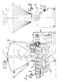
- Figure 1 shows the machine in side elevation and partly in section, the track housing for the gate members being shown as viewed in the direction of the arrow í I in Figure 2, and
- Figure 2 shows the machine as viewed from the outlet end, i.e. corresponding to viewing the machine in the direction of the arrow II in Figure 1.
- The stuffing machine shown in the drawing, designed for processing meat mass (not shown) or the like, consists in a manner known in principle of two main parts, viz.
- a filling-in
hopper 1, and - a worm pump 2.
- In a manner known per se, the
hopper 1 is provided with amovable cover 3, in the closed position shown fitting closely to thehopper 1, so that the latter may be evacuated by means of known equipment (not shown), e.g. a vacuum pump. A supply worm 4 is adapted to rotate about a vertical axis, being supported and driven by amotor assembly 5. The reason for using the term "supply worm" is that it is adapted to supply the meat mass (not shown) being present in thehopper 1 to the worm pump 2, viz. through the latter'sinlet 6. - The worm pump 2 a consists of stationary tubular housing 7, in which the pump's
worm 8 is rotatably supported. As will be evident from Figure 1, the convolutions 9 of theworm 8 are shaped like a channel having a generally semi-circular shape as seen in a longitudinal sectional view through theworm 8. Theworm 8 is adapted to be driven counter-clockwise as viewed in Figure 2 by means of a drive assembly 10 consisting of amotor 11 driving agear box 12, e.g. a planetary gear box, preferably in such a manner that theworm 8 may be driven with different speeds from 0 to 100 rpm. This is based on theworm 8 having a diameter of the order of magnitude 20-30 cm. - During the rotational movement of the
worm 8, the meat mass having been introduced through theinlet 6 by means of the supply worm 4 will be conveyed to an outlet 13. This conveying will, of course, depend on the meat mass not rotating together with theworm 8, as if so, there would not occur any cooperation between the meat mass and the convolutions 9 in the manner known e.g. from small meat mincers, in which the part corresponding to the tubular housing 7 is shaped with longitudinal grooves on the inside. - To make it quite certain that the meat mass does not rotate together with the
worm 8, the worm pump 2 is additionally provided with aworm gate assembly 14 consisting of a number - in the example shown sixteen - gate members in the form ofunconnected disks 15 being guided in an endless track in anelongated track housing 16, viz. between the latter's outer wall and aninternal guide 17 situated at a substantially constant distance from the outer wall, with the exception of arectilinear track portion 18, at which thetrack housing 16 is in open communication with the inside of the tubular housing 7, theinternal guide 17 on this side extending parallel to theworm 8. - As will be evident from Figure 2, the
track housing 16 is in the form of a flat tray or pan, closed in a fluid-tight manner by aremovable cover 19, so that the endless track, in which thedisks 15 are guided, is also delimited by the bottom of thetrack housing 16 and by thecover 19. - The inside of the tubular housing 7 and the inside of the
track housing 16 communicate with each other through aslot 20, through which thedisk 15 can protrude into the housing 7 and engage the convolutions 9 in theworm 8. Since thedisks 15 are constrained by thehousing 16 and the latter'scover 19 to move in a plane at least being parallel with the axis of theworm 8, these disks will, when the worm rotates, be moved towards the outlet 13, and in all parts of this movement between the point of initial engagement with theworm 8 and the point of disengagement, they provide a highly effective obstruction for meat mass, that could otherwise tend to follow the rotation of theworm 8 and hence not be moved towards the outlet 13. Thus, during the rotation of theworm 8, thedisks 15 will be constrained by the endless track in thehousing 16 to move as if they were parts of an endless chain, even though they are not connected to each other in any manner whatsoever. - As will be evident from the present description and the drawing, the gate members in the
worm gate assembly 14 are constituted by a number of flat,circular discs 15. It does, however, lie within the scope of the present invention to use gate members of a different shape, provided of course, that they engage in a fluid-tight manner with the convolutions 9 in theworm 8 and can move together with these in the manner described. Thus, it could be possible to use ball-shaped or double-cone-shaped gate members, the track housings corresponding to thetrack housing 16 then, of course, to be shaped in such a manner that they can guide such gate members in the same manner as thetrack housing 16 guides thedisks 15. - As will be evident from Figure 1, the end of the tubular housing 7 at the greatest distance from the outlet 13 is provided with evacuation means in the form of a
vacuum connection 21, being connected to a vacuum pump (not shown) or the like through a "vacuum trap" 22 and a vacuum conduit 23. When thevacuum connection 21 in this manner is situated in a location, at which the convolutions 9 and thedisks 15 have not yet engaged the meat mass being supplied through theinlet 6, the air may be evacuated from the convolutions 9 before the latter - relatively speaking - reach the meat mass, the latter for this reason filling the convolutions completely without forming air pockets. - Since the worm pump 2, due to the effect of the
disks 15, functions as a volumetric pump, and the formation of air pockets is prevented by means of thevacuum connection 21, the volume of meat mass being conveyed per revolution will be substantially constant, so that the number of revolutions of theworm 8 can be taken as a measure of the volume of the meat mass being ejected through the outlet 13. - As will also be evident from Figure 1, the
disks 15 are moved into full engagement with the convolutions 9 on theworm 8 at an appreciable distance from the location, viz. at theinlet 6, where the meat mass first comes into contact with theworm 8. This arrangement prevents lumps of meat from getting jammed between one or more of thedisks 15 and theconvolutions 19, before the disks hav been moved into full engagement with the convolutions 9, and thus, the risk of shearing of meat lumps at this location is avoided. At the transition between theinlet 6 and the part of the tubular housing 7 situated downstream from the inlet there is, however, a certain risk that lumps of meat can get jammed between the inside of the tubular housing 7 and the ridge of the convolutions 9 on theworm 8, and in order to minimize this risk an inclined wall 24 has been placed at this transition. Due to the inherent elastic properties of the lumps of meat, the majority of such lumps possibly getting jammed between the ridge of the convolutions 9 and the inclined wall 24 will slip forwards or backwards and hence avoid being sheared between the housing 7 and the ridge of the convolutions. - The health authorities of most countries require machines for processing meat to be opened, cleaned and disinfected completely with short intervals, e.g., at least once a day. With regard to the
worm gate assembly 14, this requirement can easily be met by opening thecover 19 and removing thedisks 15, after which it is easy to clean both the inside of thehousing 16 including the lower side of thecover 19, and thedisks 15 proper. In addition to the advantage with regard to a long-lasting and efficient gating engagement with theworm 8, achieved by using loose gate members, e.g. thedisks 15 as shown, a substantial economic advantage is achieved, partly because such loose gate members are considerably simpler and cheaper to produce than the previously used toothed disks, partly because the loose gate members can be replaced singly, if one of them were to have been damaged. - As will be evident from figure 2, the
track housing 16 is shaped and oriented in such a manner, that thedisks 15 do not fall out upon removal of thecover 19. This is especially an advantage when the disks are to be put back in place after the cleaning, as it would otherwise be necessary to use special leans for holding them in place until the track housing had been closed. - It is not shown or described herein, how the stuffing machine shown is provided with the requisite gaskets, bearings, fittings, etc. so as to be able to function as intended. Persons skilled in this art will, however, know how to design, shape, and place such means.
-
- 1
- hopper
- 2
- worm pump
- 3
- cover
- 4
- supply worm
- 5
- motor assembly
- 6
- inlet
- 7
- tubular housing
- 8
- worm
- 9
- convolutions
- 10
- drive assembly
- 11
- motor
- 12
- gear box
- 13
- outlet
- 14
- worm gate assembly
- 15
- disk/gate member
- 16
- track housing
- 17
- internal guide
- 18
- rectilinear track portion
- 19
- cover
- 20
- slot
- 21
- vacuum connection
- 22
- "vacuum trap"
- 23
- vacuum conduit
- 24
- inclined wall
Claims (2)
- Worm pump for thick media and/or media containing lumps, e.g. meat in pieces, and of the kind comprisinga) a generally rotationally symmetrical tubular housing (7) with an inlet (6) and an outlet (13), comprised in a worm-pump housing (2),b) a worm rotor (8) rotatably supported in the tubular housing (7), andc) convolution-blocking means comprisingcharacterized inc1) a track housing (16) situated laterally of the tubular housing (7) and containing at least part of an endless track limited inwardly solely by a guide member (17) surrounded by the track and outwardly partly by the inside wall of the track housing (16), partly by said worm rotor (8), so as to keep the gate members (15) in the desired track configuration, andc2) a number of loose gate members (15) supported for movement along said endless track, said gate members (15) in the part (18) of said endless track not limited by the inside wall of the track housing (16) engaging sealingly with the convolutions (9) of the worm rotor (8), whereasc3) said part (18) of the endless track with at least part of its width, as measured parallel to the plane of said endless track and transversely of the rotational axis of said worm rotor (8), extends outside of the worm-pump housing (2), and whereasc4) the track housing (16) is adapted to be opened easily in such a manner, that the gate members (15) may be removed from and inserted in the endless track transversely of the operational direction of movement of said loose gate members (15),d) that the track housing (16) comprisesd1) a tray-shaped or pan-shaped lower part, to or in which said guide member (17) is secured or shaped, as well asd2) a removable lid or cover (19) adapted to close said lower part sealingly against the surroundings.
- Pump according to claim 1, characterized ina) that the rotational axis of the worm (8) extends in a non-vertical manner, andb) that the track housing (16) is oriented in such a manner about said rotational axis, that the side of said tray-shaped or pan-shaped lower part normally closed by said removable lid or cover (19) faces obliquely upwardly.
Applications Claiming Priority (2)
| Application Number | Priority Date | Filing Date | Title |
|---|---|---|---|
| DK636/92 | 1992-05-14 | ||
| DK199200636A DK174039B1 (en) | 1992-05-14 | 1992-05-14 | Snail pump for viscous and / or lubricating media, e.g. meat. |
Publications (2)
| Publication Number | Publication Date |
|---|---|
| EP0569959A1 EP0569959A1 (en) | 1993-11-18 |
| EP0569959B1 true EP0569959B1 (en) | 1997-03-05 |
Family
ID=8095829
Family Applications (1)
| Application Number | Title | Priority Date | Filing Date |
|---|---|---|---|
| EP93107722A Expired - Lifetime EP0569959B1 (en) | 1992-05-14 | 1993-05-12 | Screw pump |
Country Status (6)
| Country | Link |
|---|---|
| US (1) | US5364251A (en) |
| EP (1) | EP0569959B1 (en) |
| AT (1) | ATE149643T1 (en) |
| DE (1) | DE69308370T2 (en) |
| DK (1) | DK174039B1 (en) |
| ES (1) | ES2098585T3 (en) |
Families Citing this family (8)
| Publication number | Priority date | Publication date | Assignee | Title |
|---|---|---|---|---|
| US6685549B2 (en) * | 2002-05-29 | 2004-02-03 | David F. Henry | Method and device for increasing the shelf life of an oxygen sensitive product |
| DK1829451T3 (en) * | 2006-03-02 | 2008-09-08 | Handtmann Albert Maschf | Filling machine and method for feeding paste masses from a hopper to a transport network |
| DE502006002192D1 (en) | 2006-03-09 | 2009-01-08 | Handtmann Albert Maschf | Device for level control and for controlled evacuation of pasty masses |
| US20070237642A1 (en) * | 2006-04-10 | 2007-10-11 | Murrow Kurt D | Axial flow positive displacement worm pump |
| EP3150072B1 (en) * | 2015-09-29 | 2019-05-15 | Albert Handtmann Maschinenfabrik GmbH & Co. KG | Filling machine and method for measuring a fill level with radar sensor, in particular in sausage making |
| DE102017125668B3 (en) | 2017-11-03 | 2018-10-18 | Ifm Electronic Gmbh | Ball screw with adjustable preload |
| DE102018129516A1 (en) | 2018-11-23 | 2020-05-28 | Ifm Electronic Gmbh | Ball screw drive with adjustable preload |
| DE102019109359A1 (en) * | 2019-04-09 | 2020-10-15 | Ifm Electronic Gmbh | Ball screw drive with adjustable preload |
Family Cites Families (9)
| Publication number | Priority date | Publication date | Assignee | Title |
|---|---|---|---|---|
| US1306572A (en) * | 1919-06-10 | l bartlett | ||
| US1941141A (en) * | 1932-06-27 | 1933-12-26 | Lubrication Corp | Pump |
| US2577361A (en) * | 1949-08-03 | 1951-12-04 | Int Harvester Co | Ball pump |
| US2837762A (en) * | 1953-11-12 | 1958-06-10 | Azzini Antonio | Rotary material press |
| FR1169709A (en) * | 1956-03-17 | 1959-01-05 | Improvement in rotary pumps | |
| GB824798A (en) * | 1956-03-17 | 1959-12-02 | Andre Affolter | Rotary fluid pump |
| US2963735A (en) * | 1956-10-25 | 1960-12-13 | Heinz Becker | Machines for introducing foodstuffs into containers |
| DE3408967A1 (en) * | 1984-03-12 | 1985-09-12 | Karl 8551 Gößweinstein Rinderle | Apparatus for delivering and/or compressing materials of various types |
| DE3712144A1 (en) * | 1987-04-10 | 1988-10-20 | August Mayr | Screw conveyor |
-
1992
- 1992-05-14 DK DK199200636A patent/DK174039B1/en not_active IP Right Cessation
-
1993
- 1993-05-12 EP EP93107722A patent/EP0569959B1/en not_active Expired - Lifetime
- 1993-05-12 AT AT93107722T patent/ATE149643T1/en not_active IP Right Cessation
- 1993-05-12 DE DE69308370T patent/DE69308370T2/en not_active Expired - Fee Related
- 1993-05-12 ES ES93107722T patent/ES2098585T3/en not_active Expired - Lifetime
- 1993-05-14 US US08/061,035 patent/US5364251A/en not_active Expired - Lifetime
Also Published As
| Publication number | Publication date |
|---|---|
| DK63692A (en) | 1993-11-15 |
| DK63692D0 (en) | 1992-05-14 |
| ES2098585T3 (en) | 1997-05-01 |
| US5364251A (en) | 1994-11-15 |
| ATE149643T1 (en) | 1997-03-15 |
| EP0569959A1 (en) | 1993-11-18 |
| DE69308370T2 (en) | 1997-06-12 |
| DK174039B1 (en) | 2002-05-06 |
| DE69308370D1 (en) | 1997-04-10 |
Similar Documents
| Publication | Publication Date | Title |
|---|---|---|
| EP0569959B1 (en) | Screw pump | |
| RU2272178C2 (en) | Screw mechanism for transporting fluid and/or solid particles | |
| JP5863733B2 (en) | Twin screw pump | |
| US4519904A (en) | Continuous filtering system for cooking oil | |
| US5567140A (en) | Keyed insert plate for curved rotary lobe pump chamber walls | |
| KR830010302A (en) | Rotary Gear with Low Pressure Bearing Lubrication Mechanism | |
| US4984975A (en) | Rotary pump with cutting means | |
| US5188524A (en) | Pivoting vane rotary compressor | |
| US5833152A (en) | Integrated comminuting screening and shredding system for liquid waste channels | |
| EP0051815A1 (en) | Pump comprising locking means for a flexible tube | |
| US1902347A (en) | Rotary gear pump | |
| RU2004103977A (en) | DOUBLE AUGER PUMP FOR FLUID SOLIDS WITH OVERLOAD PROTECTION | |
| CN210064546U (en) | Storage bin | |
| EP1544138A1 (en) | Loss-in-weight feeder for powders and dry goods | |
| CN217101644U (en) | Embedded scraper transporter | |
| US4072253A (en) | Rotary feeder | |
| US5352150A (en) | Feeding device installed in a loading bin, for special use in a sausage filling machine | |
| KR20160061074A (en) | a filling machine of processed food | |
| US3315792A (en) | Valve for conveyors | |
| US5409147A (en) | Cantilevered rotary valve | |
| JP4495827B2 (en) | Granule transportation equipment | |
| EP0713727B1 (en) | Macerator | |
| NL9001875A (en) | LOBBY ROTOR PUMP. | |
| AU2006233129A1 (en) | Open top meat skinning device | |
| CN210057956U (en) | Upper cover structure of integrated machine shell of mixing machine |
Legal Events
| Date | Code | Title | Description |
|---|---|---|---|
| PUAI | Public reference made under article 153(3) epc to a published international application that has entered the european phase |
Free format text: ORIGINAL CODE: 0009012 |
|
| AK | Designated contracting states |
Kind code of ref document: A1 Designated state(s): AT BE CH DE DK ES FR GB GR IE IT LI LU MC NL PT SE |
|
| 17P | Request for examination filed |
Effective date: 19940511 |
|
| 17Q | First examination report despatched |
Effective date: 19951017 |
|
| GRAG | Despatch of communication of intention to grant |
Free format text: ORIGINAL CODE: EPIDOS AGRA |
|
| GRAH | Despatch of communication of intention to grant a patent |
Free format text: ORIGINAL CODE: EPIDOS IGRA |
|
| GRAH | Despatch of communication of intention to grant a patent |
Free format text: ORIGINAL CODE: EPIDOS IGRA |
|
| GRAA | (expected) grant |
Free format text: ORIGINAL CODE: 0009210 |
|
| AK | Designated contracting states |
Kind code of ref document: B1 Designated state(s): AT BE CH DE DK ES FR GB GR IE IT LI LU MC NL PT SE |
|
| PG25 | Lapsed in a contracting state [announced via postgrant information from national office to epo] |
Ref country code: LI Effective date: 19970305 Ref country code: IT Free format text: LAPSE BECAUSE OF FAILURE TO SUBMIT A TRANSLATION OF THE DESCRIPTION OR TO PAY THE FEE WITHIN THE PRE;WARNING: LAPSES OF ITALIAN PATENTS WITH EFFECTIVE DATE BEFORE 2007 MAY HAVE OCCURRED AT ANY TIME BEFORE 2007. THE CORRECT EFFECTIVE DATE MAY BE DIFFERENT FROM THE ONE RECORDED.SCRIBED TIME-LIMIT Effective date: 19970305 Ref country code: GR Free format text: LAPSE BECAUSE OF FAILURE TO SUBMIT A TRANSLATION OF THE DESCRIPTION OR TO PAY THE FEE WITHIN THE PRESCRIBED TIME-LIMIT Effective date: 19970305 Ref country code: DK Effective date: 19970305 Ref country code: CH Effective date: 19970305 Ref country code: BE Effective date: 19970305 Ref country code: AT Effective date: 19970305 |
|
| REF | Corresponds to: |
Ref document number: 149643 Country of ref document: AT Date of ref document: 19970315 Kind code of ref document: T |
|
| REG | Reference to a national code |
Ref country code: CH Ref legal event code: EP |
|
| REF | Corresponds to: |
Ref document number: 69308370 Country of ref document: DE Date of ref document: 19970410 |
|
| REG | Reference to a national code |
Ref country code: ES Ref legal event code: FG2A Ref document number: 2098585 Country of ref document: ES Kind code of ref document: T3 |
|
| REG | Reference to a national code |
Ref country code: IE Ref legal event code: FG4D Free format text: 72310 |
|
| PG25 | Lapsed in a contracting state [announced via postgrant information from national office to epo] |
Ref country code: LU Free format text: LAPSE BECAUSE OF NON-PAYMENT OF DUE FEES Effective date: 19970512 Ref country code: IE Free format text: LAPSE BECAUSE OF NON-PAYMENT OF DUE FEES Effective date: 19970512 |
|
| PG25 | Lapsed in a contracting state [announced via postgrant information from national office to epo] |
Ref country code: SE Effective date: 19970605 Ref country code: PT Effective date: 19970605 |
|
| ET | Fr: translation filed | ||
| REG | Reference to a national code |
Ref country code: CH Ref legal event code: PL |
|
| PG25 | Lapsed in a contracting state [announced via postgrant information from national office to epo] |
Ref country code: MC Effective date: 19971130 |
|
| PLBE | No opposition filed within time limit |
Free format text: ORIGINAL CODE: 0009261 |
|
| STAA | Information on the status of an ep patent application or granted ep patent |
Free format text: STATUS: NO OPPOSITION FILED WITHIN TIME LIMIT |
|
| 26N | No opposition filed | ||
| REG | Reference to a national code |
Ref country code: GB Ref legal event code: IF02 |
|
| NLS | Nl: assignments of ep-patents |
Owner name: CFS SLAGELSE A/S |
|
| REG | Reference to a national code |
Ref country code: FR Ref legal event code: TP |
|
| PGFP | Annual fee paid to national office [announced via postgrant information from national office to epo] |
Ref country code: ES Payment date: 20080523 Year of fee payment: 16 |
|
| PGFP | Annual fee paid to national office [announced via postgrant information from national office to epo] |
Ref country code: NL Payment date: 20080523 Year of fee payment: 16 Ref country code: DE Payment date: 20080724 Year of fee payment: 16 |
|
| PGFP | Annual fee paid to national office [announced via postgrant information from national office to epo] |
Ref country code: GB Payment date: 20080522 Year of fee payment: 16 |
|
| GBPC | Gb: european patent ceased through non-payment of renewal fee |
Effective date: 20090512 |
|
| NLV4 | Nl: lapsed or anulled due to non-payment of the annual fee |
Effective date: 20091201 |
|
| PG25 | Lapsed in a contracting state [announced via postgrant information from national office to epo] |
Ref country code: NL Free format text: LAPSE BECAUSE OF NON-PAYMENT OF DUE FEES Effective date: 20091201 |
|
| REG | Reference to a national code |
Ref country code: FR Ref legal event code: ST Effective date: 20100129 |
|
| PG25 | Lapsed in a contracting state [announced via postgrant information from national office to epo] |
Ref country code: FR Free format text: LAPSE BECAUSE OF NON-PAYMENT OF DUE FEES Effective date: 20090602 |
|
| PGFP | Annual fee paid to national office [announced via postgrant information from national office to epo] |
Ref country code: FR Payment date: 20080519 Year of fee payment: 16 |
|
| PG25 | Lapsed in a contracting state [announced via postgrant information from national office to epo] |
Ref country code: GB Free format text: LAPSE BECAUSE OF NON-PAYMENT OF DUE FEES Effective date: 20090512 |
|
| PG25 | Lapsed in a contracting state [announced via postgrant information from national office to epo] |
Ref country code: DE Free format text: LAPSE BECAUSE OF NON-PAYMENT OF DUE FEES Effective date: 20091201 |
|
| REG | Reference to a national code |
Ref country code: ES Ref legal event code: FD2A Effective date: 20090513 |
|
| PG25 | Lapsed in a contracting state [announced via postgrant information from national office to epo] |
Ref country code: ES Free format text: LAPSE BECAUSE OF NON-PAYMENT OF DUE FEES Effective date: 20090513 |