EP0568676B1 - Endoprothese - Google Patents
Endoprothese Download PDFInfo
- Publication number
- EP0568676B1 EP0568676B1 EP92923803A EP92923803A EP0568676B1 EP 0568676 B1 EP0568676 B1 EP 0568676B1 EP 92923803 A EP92923803 A EP 92923803A EP 92923803 A EP92923803 A EP 92923803A EP 0568676 B1 EP0568676 B1 EP 0568676B1
- Authority
- EP
- European Patent Office
- Prior art keywords
- prosthesis
- lugs
- pct
- endoprosthesis
- plates
- Prior art date
- Legal status (The legal status is an assumption and is not a legal conclusion. Google has not performed a legal analysis and makes no representation as to the accuracy of the status listed.)
- Expired - Lifetime
Links
- 230000007704 transition Effects 0.000 claims abstract description 5
- 230000008719 thickening Effects 0.000 abstract 1
- 210000000988 bone and bone Anatomy 0.000 description 7
- 208000037873 arthrodesis Diseases 0.000 description 2
- 238000006073 displacement reaction Methods 0.000 description 2
- 238000002513 implantation Methods 0.000 description 2
- 238000005452 bending Methods 0.000 description 1
- 230000005540 biological transmission Effects 0.000 description 1
- 239000003795 chemical substances by application Substances 0.000 description 1
- 230000000295 complement effect Effects 0.000 description 1
- 230000000694 effects Effects 0.000 description 1
- 238000005516 engineering process Methods 0.000 description 1
- 239000012634 fragment Substances 0.000 description 1
- 230000001771 impaired effect Effects 0.000 description 1
- 230000003993 interaction Effects 0.000 description 1
- 210000000629 knee joint Anatomy 0.000 description 1
- 230000002093 peripheral effect Effects 0.000 description 1
Images
Classifications
-
- A—HUMAN NECESSITIES
- A61—MEDICAL OR VETERINARY SCIENCE; HYGIENE
- A61F—FILTERS IMPLANTABLE INTO BLOOD VESSELS; PROSTHESES; DEVICES PROVIDING PATENCY TO, OR PREVENTING COLLAPSING OF, TUBULAR STRUCTURES OF THE BODY, e.g. STENTS; ORTHOPAEDIC, NURSING OR CONTRACEPTIVE DEVICES; FOMENTATION; TREATMENT OR PROTECTION OF EYES OR EARS; BANDAGES, DRESSINGS OR ABSORBENT PADS; FIRST-AID KITS
- A61F2/00—Filters implantable into blood vessels; Prostheses, i.e. artificial substitutes or replacements for parts of the body; Appliances for connecting them with the body; Devices providing patency to, or preventing collapsing of, tubular structures of the body, e.g. stents
- A61F2/02—Prostheses implantable into the body
- A61F2/28—Bones
-
- A—HUMAN NECESSITIES
- A61—MEDICAL OR VETERINARY SCIENCE; HYGIENE
- A61F—FILTERS IMPLANTABLE INTO BLOOD VESSELS; PROSTHESES; DEVICES PROVIDING PATENCY TO, OR PREVENTING COLLAPSING OF, TUBULAR STRUCTURES OF THE BODY, e.g. STENTS; ORTHOPAEDIC, NURSING OR CONTRACEPTIVE DEVICES; FOMENTATION; TREATMENT OR PROTECTION OF EYES OR EARS; BANDAGES, DRESSINGS OR ABSORBENT PADS; FIRST-AID KITS
- A61F2/00—Filters implantable into blood vessels; Prostheses, i.e. artificial substitutes or replacements for parts of the body; Appliances for connecting them with the body; Devices providing patency to, or preventing collapsing of, tubular structures of the body, e.g. stents
- A61F2/02—Prostheses implantable into the body
- A61F2/30—Joints
- A61F2/38—Joints for elbows or knees
Definitions
- the invention relates to an endoprosthesis with two prosthesis parts connected by an overlap connection.
- a prosthesis for rigid connection of two bone fragments or for arthrodesis of two tubular bones that are otherwise connected by a joint At the point of fracture or joint, the two bones can be angled against each other so that the stems of the two prostheses can be inserted into the bones. Then the bones are aligned with each other and the parts of the prosthesis facing each other are connected. This can be done, for example, in a form-fitting manner using a cone or pin at the end of one shaft, which is inserted into a corresponding sleeve at the end of the other shaft.
- the invention avoids these disadvantages in the case of a tab connection in that the ends of the overlapping tabs are positively received by pockets on the other part of the prosthesis.
- To couple the tabs together only a small distraction is required, the length of which corresponds to the length of the engagement of the tab ends in the associated pockets. This length is significantly less than with a tenon or cone connection, in which a distraction over practically the entire length of the connection area is required.
- an engagement length of the tab ends into the associated pockets of not more than 1/5, preferably not more than 1/10 of the total overlap length is sufficient.
- Devices for securing the tabs in the engagement position are expediently provided, which merely need to ensure that no longitudinal displacement of the tabs relative to one another can take place, through which the tab ends could get out of the associated pockets.
- the relevant technology provides such agents in various forms. The easiest way is to screw the tabs together. It is noteworthy that the screw connection prevents longitudinal displacement even if a screw should have loosened a little. In contrast to the known, screwed tab connections the security of the connection is not impaired by the screw loosening.
- the tabs near their transition into the associated prosthesis part are thicker than at their free end in that the contact surface, which they face each other, is inclined to the common longitudinal axis of the connecting area of the prosthesis parts. Because the tabs are thickest at the end at which they are firmly connected to the associated prosthesis part, they can pass into the prosthesis part with the same cross section without forming dangerous notches, while their end engaging in the pocket of the other prosthesis part is correspondingly thinner.
- the bevel allows the tab ends and the pockets surrounding them to be wedged together, so that there is a self-locking, play-free engagement position.
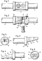
- the two prosthesis parts each have a shaft 1 for implantation in the upper or lower leg bone.
- Your connecting area 2 comprises two mutually complementary to cylindrical outer tabs 3, the contact surface 6 extends so inclined that the thicker end 4 merges in one piece and with undiminished bending strength in the associated shaft part 1, while the free end 5 in the plane of the illustration 3 and 4 is approximately half as thick as the thicker end 4 and its cross-sectional area is approximately 1/3 as large.
- the tabs lie flat against one another along the surface 6 in the connected state according to FIGS. 1 and 2. They can be secured in this position by means of screws 7.
- each tab 3 this is enclosed by a ring 8, which includes a pocket 9 with the associated end of the contact surface 6, the cross section of which in longitudinal view according to FIGS. 5 and 6 corresponds to that of the end part 5 of the other tab.
- the dimensions are chosen so that in the play-free collapsed state, which is shown in Fig. 3, the contact surfaces 6 and the peripheral surfaces of the tab ends 5 come into play with each other or the respective ring 8, so that alone by the interaction of the Tab ends 5 with the pockets 9 a rigid connection is guaranteed.
- the security of the connection is further increased by the wedge effect of the contact surface 6 under the prosthesis load, which tries to push the two prosthesis parts together.
- the tabs are secured by screws 7, the corresponding, opposite screw holes 10, 11 being arranged such that even if they are slightly offset from one another in the assembled state, as indicated at 12, the complete engagement the tab ends 5 in the pockets 9 is guaranteed.
- the ring 8 is preferably fixedly attached to the associated prosthesis part.
- screws are used to secure the engagement, they can be used for power transmission and dimensioned accordingly.
Landscapes
- Health & Medical Sciences (AREA)
- Orthopedic Medicine & Surgery (AREA)
- Cardiology (AREA)
- Oral & Maxillofacial Surgery (AREA)
- Transplantation (AREA)
- Engineering & Computer Science (AREA)
- Biomedical Technology (AREA)
- Heart & Thoracic Surgery (AREA)
- Vascular Medicine (AREA)
- Life Sciences & Earth Sciences (AREA)
- Animal Behavior & Ethology (AREA)
- General Health & Medical Sciences (AREA)
- Public Health (AREA)
- Veterinary Medicine (AREA)
- Prostheses (AREA)
- Saccharide Compounds (AREA)
- Diaphragms For Electromechanical Transducers (AREA)
Description
- Die Erfindung betrifft eine Endoprothese mit zwei durch Überlappungsverbindung verbundenen Prothesenteilen.
- Es besteht häufig das Problem, zwei Prothesenteile nach deren gesonderter Implantation starr miteinander zu verbinden. Ein Beispiel dafür ist eine Prothese zur starren Verbindung zweier Knochenfragmente oder zur Arthrodese zweier sonst durch Gelenk verbundener Röhrenknochen. An der Bruch- bzw. Gelenkstelle können die beiden Knochen gegeneinander abgewinkelt werden, so daß die Schäfte der beiden Prothesen in die Knochen eingeführt werden können. Danach werden die Knochen zueinander ausgerichtet und die einander zugewendeten Teile der Prothesen miteinander verbunden. Dies kann bspw. formschlüssig unter Verwendung eines Konus oder Zapfens am Ende des einen Schafts geschehen, der in eine entsprechende Hülse am Ende des anderen Schafts eingeführt wird. Dies hat aber den Nachteil, daß zum Einfügen des Kegels oder Zapfens in die zugehörige Hülse die beiden Knochen zunächst um die Kegel- bzw. Zapfenlänge distrahiert werden müssen, was schwierig oder schädlich sein kann. Erwünscht ist deshalb eine Verbindung, die ohne wesentliche Distraktion geschlossen werden kann. Dafür steht die Laschenverbindung zur Verfügung, bei der zwei an den Enden der Prothesenschäfte vorgesehenen Laschen miteinander verschraubt werden, was jedoch den Nachteil hat, daß die Verläßlichkeit der Verbindung von den Schrauben abhängt, die sich lockern können, und daß der Übergang von den Laschen zu den Schäften eine Schwachstelle bildet.
- Dokument US-A-4578081 beschreibt eine Endoprothese gemäß dem Oberbegriff des Anspruchs 1.
- Die Erfindung vermeidet diese Nachteile bei einer Laschenverbindung dadurch, daß die Enden der einander überlappenden Laschen formschlüssig von Taschen am jeweils anderen Prothesenteil aufgenommen sind. Um die Laschen miteinander zu kuppeln, ist lediglich eine geringe Distraktion erforderlich, deren Länge der Länge des Eingriffs der Laschenenden in die zugehörigen Taschen entspricht. Diese Länge ist wesentlich geringer als bei einer Zapfen- bzw. Kegel-Verbindung, bei der eine Distraktion über praktisch die gesamte Länge des Verbindungsbereichs erforderlich ist.
- Erfindungsgemäß genügt eine Eingriffslänge der Laschenenden in die zugehörigen Taschen von nicht mehr als 1/5, vorzugsweise nicht mehr als 1/10 der gesamten Überlappungslänge.
- Zweckmäßigerweise sind Einrichtungen zur Sicherung der Laschen in der Eingriffsstellung vorgesehen, die lediglich dafür zu sorgen brauchen, daß keine Längsverschiebung der Laschen zueinander stattfinden kann, durch welche die Laschenenden aus den zugehörigen Taschen herausgelangen könnten. Die einschlägige Technik stellt derartige Mittel in verschiedener Form zur Verfügung. Am einfachsten ist es, die Laschen miteinander zu verschrauben. Bemerkenswert ist dabei, daß die Verschraubung die Längsverschiebung auch dann verhindert, wenn sich eine Schraube ein wenig gelockert haben sollte. Im Unterschied zu den bekannten, verschraubten Laschenverbindungen wird daher die Sicherheit der Verbindung durch die Schraubenlockerung nicht beeinträchtigt.
- Nach einem weiteren Merkmal der Erfindung sind die Laschen nahe ihrem Übergang in den zugehörigen Prothesenteil dicker als an ihrem freien Ende, indem die Anlagefläche, die sie einander zukehren, geneigt zur gemeinsamen Längsachse des Verbindungsbereichs der Prothesenteile verläuft. Dadurch daß die Laschen an demjenigen Ende, an welchem sie mit dem zugehörigen Prothesenteil fest verbunden sind, am dicksten sind, können sie querschnittsgleich ohne Ausbildung gefährlicher Kerben in den Prothesenteil übergehen, während ihr in die Tasche des anderen Prothesenteil eingreifende Ende entsprechend dünner ist. Die Schrägung erlaubt es, die Laschenenden und die sie umfassenden Taschen ineinander zu verkeilen, so daß sich eine selbsthemmende, spielfreie Eingriffsstellung ergibt.
- Die Erfindung wird im folgenden näher unter Bezugnahme auf die Zeichnung erläutert, die ein vorteilhaftes Ausführungsbeispiel einer Prothese oder Schiene für die Arthrodese des Kniegelenks zeigt. Darin stellen dar:
- Fig. 1
- den Verbindungsbereich der Prothese in Seitenansicht,
- Fig. 2
- eine Seitenansicht quer zu derjenigen gemäß Fig. 1,
- Fig. 3 und 4
- gesonderte Seitenansichten der Verbindungsbereiche der beiden Prothesenteile und
- Fig. 5 und 6
- Längsansichten der Verbindungsbereiche der Prothesenteile.
- Die beiden Prothesenteile weisen je einen Schaft 1 zur Implantation im Ober- bzw. Unterschenkelknochen auf. Ihr Verbindungsbereich 2 umfaßt zwei einander zu zylindrischer Außenform ergänzende Laschen 3, deren Anlagefläche 6 so geneigt verläuft, daß jeweils das dickere Ende 4 einstückig und mit unverminderter Biegefestigkeit in den zugehörigen Schaftteil 1 übergeht, während das freie Ende 5 in der Darstellungsebene der Fig. 3 und 4 etwa halb so dick wie das dickere Ende 4 ist und seine Querschnittsfläche etwa 1/3 so groß ist. Die Laschen liegen längs der Fläche 6 im Verbindungszustand gemäß Fig. 1 und 2 flächig aneinander. Mittels Schrauben 7 können sie in dieser Stellung gesichert werden.
- An der Wurzel jeder Lasche 3 ist diese von einem Ring 8 umschlossen, der eine Tasche 9 mit dem zugehörigen Ende der Anlagefläche 6 einschließt, deren Querschnitt in Längsansicht gemäß Fig. 5 und 6 demjenigen des Endteils 5 der jeweils anderen Lasche entspricht. Dabei sind die Abmessungen so gewählt, daß im spielfrei zusammengeschobenen Zustand, der in Fig. 3 dargestellt ist, die Anlageflächen 6 und die Umfangsflächen der Laschenenden 5 spielfrei miteinander bzw. dem jeweiligen Ring 8 in Kontakt kommen, so daß schon allein durch das Zusammenwirken der Laschenenden 5 mit den Taschen 9 eine starre Verbindung gewährleistet ist. Die Verbindungssicherheit wird dabei durch die Keilwirkung der Anlagefläche 6 unter der Prothesenbelastung, die die beiden Prothesenteile zusammenzuschieben versucht, noch gesteigert. In der Eingriffsstellung werden die Laschen durch Schrauben 7 gesichert, wobei die zusammengehörigen, gegenüberliegenden Schraublöcher 10, 11 so angeordnet sind, daß selbst dann, wenn sie im montierten Zustand ein wenig gegeneinander versetzt sind, wie dies bei 12 angedeutet ist, noch der vollständige Eingriff der Laschenenden 5 in den Taschen 9 gewährleistet ist. Der Ring 8 ist vorzugsweise fest an dem zugehörigen Prothesenteil befestigt.
- Bei Verwendung von Schrauben zur Sicherung des Eingriffs können diese zur Kraftübertragung herangezogen und entsprechend dimensioniert werden.
Claims (7)
- Endoprothese mit zwei durch einander überlappende Laschen verbundenen Prothesenteilen, dadurch gekennzeichnet, daß die Enden (5) der Laschen (3) formschlüssig von Taschen (9) am jeweils anderen Prothesenteil aufgenommen sind.
- Endoprothese nach Anspruch 1, dadurch gekennzeichnet, daß die Taschen (9) eine Länge von nicht mehr als 1/5, vorzugsweise nicht mehr als 1/10, der gesamten Laschenlänge aufweisen.
- Endoprothese nach Anspruch 1 oder 2, dadurch gekennzeichnet, daß die Laschen (3) mit Einrichtungen zur Sicherung in der Eingriffsstellung ausgerüstet sind.
- Endoprothese nach Anspruch 3, dadurch gekennzeichnet, daß die Einrichtungen zur Sicherung in der Eingriffsstellung von mindestens einer Schraube (7) gebildet sind.
- Endoprothese nach einem der Ansprüche 1 bis 4, dadurch gekennzeichnet, daß die Laschen (3) nahe ihrem Übergang in den zugehörigen Prothesenteil dicker als an ihrem freien Ende sind.
- Endoprothese nach Anspruch 5, dadurch gekennzeichnet, daß die Anlagefläche (6), die die Laschen (3) einander zukehren, geneigt zur Längsachse des Verbindungsbereichs (2) der Prothese verläuft.
- Endoprothese nach Anspruch 5 oder 6, dadurch gekennzeichnet, daß die Enden (5) der Überlappungsteile (3) und die Taschen (9) in der Eingriffsstellung spielfrei aufgrund Keilwirkung zusammenwirken.
Applications Claiming Priority (3)
| Application Number | Priority Date | Filing Date | Title |
|---|---|---|---|
| DE9114970U DE9114970U1 (de) | 1991-12-02 | 1991-12-02 | Endoprothese |
| DE9114970U | 1991-12-02 | ||
| PCT/EP1992/002730 WO1993010724A1 (de) | 1991-12-02 | 1992-11-26 | Endoprothese |
Publications (2)
| Publication Number | Publication Date |
|---|---|
| EP0568676A1 EP0568676A1 (de) | 1993-11-10 |
| EP0568676B1 true EP0568676B1 (de) | 1996-01-17 |
Family
ID=6873838
Family Applications (1)
| Application Number | Title | Priority Date | Filing Date |
|---|---|---|---|
| EP92923803A Expired - Lifetime EP0568676B1 (de) | 1991-12-02 | 1992-11-26 | Endoprothese |
Country Status (7)
| Country | Link |
|---|---|
| US (1) | US5383933A (de) |
| EP (1) | EP0568676B1 (de) |
| AT (1) | ATE133057T1 (de) |
| DE (2) | DE9114970U1 (de) |
| ES (1) | ES2084392T3 (de) |
| GR (1) | GR3019293T3 (de) |
| WO (1) | WO1993010724A1 (de) |
Families Citing this family (13)
| Publication number | Priority date | Publication date | Assignee | Title |
|---|---|---|---|---|
| US5674296A (en) | 1994-11-14 | 1997-10-07 | Spinal Dynamics Corporation | Human spinal disc prosthesis |
| DE19754079A1 (de) * | 1997-12-05 | 1999-06-10 | Gmt Medizinische Technik Gmbh | Endoprothese zum mindestens teilweisen Ersatz einer Tibia |
| ATE363877T1 (de) | 1998-07-22 | 2007-06-15 | Warsaw Orthopedic Inc | Geschraubte zylindrische, multidiskoide einfach- oder mehrfach-netzwerkplattenprothese |
| WO2000013619A1 (en) * | 1998-09-04 | 2000-03-16 | Spinal Dynamics Corporation | Peanut spectacle multi discoid thoraco-lumbar disc prosthesis |
| US6749635B1 (en) | 1998-09-04 | 2004-06-15 | Sdgi Holdings, Inc. | Peanut spectacle multi discoid thoraco-lumbar disc prosthesis |
| EP1307153B1 (de) | 2000-08-08 | 2009-09-23 | Warsaw Orthopedic, Inc. | Gerät zur stereotaktischen implantation |
| US7125380B2 (en) * | 2000-08-08 | 2006-10-24 | Warsaw Orthopedic, Inc. | Clamping apparatus and methods |
| AU8116601A (en) * | 2000-08-08 | 2002-02-18 | Spinal Dynamics Corp | Implantable joint prosthesis |
| US7601174B2 (en) * | 2000-08-08 | 2009-10-13 | Warsaw Orthopedic, Inc. | Wear-resistant endoprosthetic devices |
| US6562045B2 (en) | 2001-02-13 | 2003-05-13 | Sdgi Holdings, Inc. | Machining apparatus |
| US7025787B2 (en) * | 2001-11-26 | 2006-04-11 | Sdgi Holdings, Inc. | Implantable joint prosthesis and associated instrumentation |
| US7364589B2 (en) * | 2003-02-12 | 2008-04-29 | Warsaw Orthopedic, Inc. | Mobile bearing articulating disc |
| EP3381410A1 (de) * | 2017-03-31 | 2018-10-03 | Waldemar Link GmbH & Co. KG | Verbindungshülse für verankerungsschäfte zweier gegenüberliegend angeordneter prothesen |
Family Cites Families (5)
| Publication number | Priority date | Publication date | Assignee | Title |
|---|---|---|---|---|
| US4578081A (en) * | 1982-02-17 | 1986-03-25 | Howmedica International, Inc. | Bone prosthesis |
| US4938768A (en) * | 1987-03-09 | 1990-07-03 | Henry Ford Hospital | Bone gap bridging and fusing device |
| DE8706999U1 (de) * | 1987-05-15 | 1987-07-23 | Howmedica GmbH, 2314 Schönkirchen | Endoprothese für femorale oder tibiale Gelenkknochenteile und angrenzende Knochenabschnitte |
| SU1671286A1 (ru) * | 1988-10-13 | 1991-08-23 | Б.Г.Зимлицкий и Е.Д.Соломко | Эндопротез диафиза |
| IT1234281B (it) * | 1989-06-09 | 1992-05-14 | Roltra Spa | Protesi per la riduzione e il bloccaggio di fratture ossee di arti |
-
1991
- 1991-12-02 DE DE9114970U patent/DE9114970U1/de not_active Expired - Lifetime
-
1992
- 1992-11-26 ES ES92923803T patent/ES2084392T3/es not_active Expired - Lifetime
- 1992-11-26 WO PCT/EP1992/002730 patent/WO1993010724A1/de not_active Ceased
- 1992-11-26 EP EP92923803A patent/EP0568676B1/de not_active Expired - Lifetime
- 1992-11-26 DE DE59205114T patent/DE59205114D1/de not_active Expired - Lifetime
- 1992-11-26 US US08/094,082 patent/US5383933A/en not_active Expired - Lifetime
- 1992-11-26 AT AT92923803T patent/ATE133057T1/de active
-
1996
- 1996-03-13 GR GR960400697T patent/GR3019293T3/el unknown
Also Published As
| Publication number | Publication date |
|---|---|
| WO1993010724A1 (de) | 1993-06-10 |
| GR3019293T3 (en) | 1996-06-30 |
| ATE133057T1 (de) | 1996-02-15 |
| DE59205114D1 (de) | 1996-02-29 |
| US5383933A (en) | 1995-01-24 |
| ES2084392T3 (es) | 1996-05-01 |
| EP0568676A1 (de) | 1993-11-10 |
| DE9114970U1 (de) | 1992-02-20 |
Similar Documents
| Publication | Publication Date | Title |
|---|---|---|
| DE69512489T2 (de) | Gelenkelement für äussere Fixationskomponenten | |
| EP0547476B1 (de) | Kniegelenkendoprothese | |
| EP0546460B1 (de) | Osteosynthesehilfsmittel bei pertrochantärem Oberschenkelhalsbruch | |
| EP1639968A1 (de) | Implantat mit einem in eine Knochenhöhlung einzusetzenden und darin zu verankernden Teil | |
| EP0570929B1 (de) | Implantat für die Wirbeläule | |
| EP1418852A1 (de) | Interspinale prothese | |
| EP1815812A1 (de) | Wirbelsäulenimplantat | |
| EP1414624A1 (de) | Handwerkzeugmaschine mit vibrationsgedämpftem handgriff | |
| EP1287787A1 (de) | Implantat zur gegenseitigen Fixierung zweier Knochenfragmente | |
| DE3138848A1 (de) | Endoprothese zum ersatz stabfoermiger knochen | |
| DE9114970U1 (de) | Endoprothese | |
| DE3336004C2 (de) | Adapter für eine Knochen-Endoprothese | |
| EP0350925B1 (de) | Externe Knochenbruchteil-Verbindungsvorrichtung | |
| EP2877098B1 (de) | Halter für ein medizinisches, insbesondere chirurgisches instrument | |
| EP1833393A1 (de) | Osteosyntheseplatte, beispielsweise radius- oder humeruskopfplatte, mit einer vielzahl von bohrungen zur aufnahme von knochenschrauben | |
| EP2257245B1 (de) | Medizinisches implantat und kniegelenkendoprothese | |
| EP1088531A1 (de) | Gelenkendoprothese | |
| DE10328307A1 (de) | Wirbelkörperprothese | |
| EP2846738B1 (de) | Verstärkungsimplantat für einen langgestreckten knochen, insbesondere femur | |
| AT406013B (de) | Lösbare spannvorrichtung für ein rotierendes medizinisches oder dentales werkzeug | |
| DE8624671U1 (de) | Osteosyntheseplatte | |
| EP3381410A1 (de) | Verbindungshülse für verankerungsschäfte zweier gegenüberliegend angeordneter prothesen | |
| EP1764060A1 (de) | Zahnimplantat | |
| DE3935488C2 (de) | ||
| DE3730570C2 (de) |
Legal Events
| Date | Code | Title | Description |
|---|---|---|---|
| PUAI | Public reference made under article 153(3) epc to a published international application that has entered the european phase |
Free format text: ORIGINAL CODE: 0009012 |
|
| 17P | Request for examination filed |
Effective date: 19930714 |
|
| AK | Designated contracting states |
Kind code of ref document: A1 Designated state(s): AT BE CH DE ES FR GB GR IT LI NL SE |
|
| 17Q | First examination report despatched |
Effective date: 19950321 |
|
| GRAA | (expected) grant |
Free format text: ORIGINAL CODE: 0009210 |
|
| AK | Designated contracting states |
Kind code of ref document: B1 Designated state(s): AT BE CH DE ES FR GB GR IT LI NL SE |
|
| REF | Corresponds to: |
Ref document number: 133057 Country of ref document: AT Date of ref document: 19960215 Kind code of ref document: T |
|
| REF | Corresponds to: |
Ref document number: 59205114 Country of ref document: DE Date of ref document: 19960229 |
|
| REG | Reference to a national code |
Ref country code: CH Ref legal event code: NV Representative=s name: TROESCH SCHEIDEGGER WERNER AG |
|
| ITF | It: translation for a ep patent filed | ||
| ET | Fr: translation filed | ||
| REG | Reference to a national code |
Ref country code: ES Ref legal event code: FG2A Ref document number: 2084392 Country of ref document: ES Kind code of ref document: T3 |
|
| GBT | Gb: translation of ep patent filed (gb section 77(6)(a)/1977) |
Effective date: 19960423 |
|
| REG | Reference to a national code |
Ref country code: GR Ref legal event code: FG4A Free format text: 3019293 |
|
| PLBE | No opposition filed within time limit |
Free format text: ORIGINAL CODE: 0009261 |
|
| STAA | Information on the status of an ep patent application or granted ep patent |
Free format text: STATUS: NO OPPOSITION FILED WITHIN TIME LIMIT |
|
| 26N | No opposition filed | ||
| REG | Reference to a national code |
Ref country code: GB Ref legal event code: IF02 |
|
| PGFP | Annual fee paid to national office [announced via postgrant information from national office to epo] |
Ref country code: AT Payment date: 20101119 Year of fee payment: 19 |
|
| PGFP | Annual fee paid to national office [announced via postgrant information from national office to epo] |
Ref country code: GR Payment date: 20101123 Year of fee payment: 19 Ref country code: IT Payment date: 20101126 Year of fee payment: 19 Ref country code: GB Payment date: 20101123 Year of fee payment: 19 |
|
| PGFP | Annual fee paid to national office [announced via postgrant information from national office to epo] |
Ref country code: FR Payment date: 20111125 Year of fee payment: 20 Ref country code: NL Payment date: 20111123 Year of fee payment: 20 Ref country code: ES Payment date: 20111123 Year of fee payment: 20 Ref country code: SE Payment date: 20111122 Year of fee payment: 20 Ref country code: CH Payment date: 20111124 Year of fee payment: 20 |
|
| PGFP | Annual fee paid to national office [announced via postgrant information from national office to epo] |
Ref country code: BE Payment date: 20111122 Year of fee payment: 20 |
|
| PGFP | Annual fee paid to national office [announced via postgrant information from national office to epo] |
Ref country code: DE Payment date: 20120125 Year of fee payment: 20 |
|
| REG | Reference to a national code |
Ref country code: GR Ref legal event code: ML Ref document number: 960400697 Country of ref document: GR Effective date: 20120605 |
|
| PG25 | Lapsed in a contracting state [announced via postgrant information from national office to epo] |
Ref country code: GR Free format text: LAPSE BECAUSE OF NON-PAYMENT OF DUE FEES Effective date: 20120605 |
|
| REG | Reference to a national code |
Ref country code: DE Ref legal event code: R071 Ref document number: 59205114 Country of ref document: DE |
|
| REG | Reference to a national code |
Ref country code: DE Ref legal event code: R071 Ref document number: 59205114 Country of ref document: DE |
|
| BE20 | Be: patent expired |
Owner name: *WALDEMAR LINK (G.M.B.H. & CO.) Effective date: 20121126 |
|
| REG | Reference to a national code |
Ref country code: NL Ref legal event code: V4 Effective date: 20121126 |
|
| REG | Reference to a national code |
Ref country code: CH Ref legal event code: PL |
|
| REG | Reference to a national code |
Ref country code: AT Ref legal event code: MM01 Ref document number: 133057 Country of ref document: AT Kind code of ref document: T Effective date: 20111126 |
|
| REG | Reference to a national code |
Ref country code: GB Ref legal event code: PE20 Expiry date: 20121125 |
|
| REG | Reference to a national code |
Ref country code: SE Ref legal event code: EUG |
|
| PG25 | Lapsed in a contracting state [announced via postgrant information from national office to epo] |
Ref country code: GB Free format text: LAPSE BECAUSE OF EXPIRATION OF PROTECTION Effective date: 20121125 Ref country code: AT Free format text: LAPSE BECAUSE OF NON-PAYMENT OF DUE FEES Effective date: 20111126 |
|
| REG | Reference to a national code |
Ref country code: ES Ref legal event code: FD2A Effective date: 20130725 |
|
| PG25 | Lapsed in a contracting state [announced via postgrant information from national office to epo] |
Ref country code: ES Free format text: LAPSE BECAUSE OF EXPIRATION OF PROTECTION Effective date: 20121127 |