EP0568227A1 - Panneau à structure sandwich résistant au feu - Google Patents
Panneau à structure sandwich résistant au feu Download PDFInfo
- Publication number
- EP0568227A1 EP0568227A1 EP93302998A EP93302998A EP0568227A1 EP 0568227 A1 EP0568227 A1 EP 0568227A1 EP 93302998 A EP93302998 A EP 93302998A EP 93302998 A EP93302998 A EP 93302998A EP 0568227 A1 EP0568227 A1 EP 0568227A1
- Authority
- EP
- European Patent Office
- Prior art keywords
- panel
- pair
- tongue
- joining members
- steel
- Prior art date
- Legal status (The legal status is an assumption and is not a legal conclusion. Google has not performed a legal analysis and makes no representation as to the accuracy of the status listed.)
- Granted
Links
Images

Classifications
-
- E—FIXED CONSTRUCTIONS
- E04—BUILDING
- E04C—STRUCTURAL ELEMENTS; BUILDING MATERIALS
- E04C2/00—Building elements of relatively thin form for the construction of parts of buildings, e.g. sheet materials, slabs, or panels
- E04C2/02—Building elements of relatively thin form for the construction of parts of buildings, e.g. sheet materials, slabs, or panels characterised by specified materials
- E04C2/26—Building elements of relatively thin form for the construction of parts of buildings, e.g. sheet materials, slabs, or panels characterised by specified materials composed of materials covered by two or more of groups E04C2/04, E04C2/08, E04C2/10 or of materials covered by one of these groups with a material not specified in one of the groups
- E04C2/284—Building elements of relatively thin form for the construction of parts of buildings, e.g. sheet materials, slabs, or panels characterised by specified materials composed of materials covered by two or more of groups E04C2/04, E04C2/08, E04C2/10 or of materials covered by one of these groups with a material not specified in one of the groups at least one of the materials being insulating
- E04C2/292—Building elements of relatively thin form for the construction of parts of buildings, e.g. sheet materials, slabs, or panels characterised by specified materials composed of materials covered by two or more of groups E04C2/04, E04C2/08, E04C2/10 or of materials covered by one of these groups with a material not specified in one of the groups at least one of the materials being insulating composed of insulating material and sheet metal
-
- E—FIXED CONSTRUCTIONS
- E04—BUILDING
- E04F—FINISHING WORK ON BUILDINGS, e.g. STAIRS, FLOORS
- E04F2201/00—Joining sheets or plates or panels
- E04F2201/04—Other details of tongues or grooves
- E04F2201/041—Tongues or grooves with slits or cuts for expansion or flexibility
Definitions
- the present invention relates to a sandwich wall system panel.
- insulating core sandwiched between first and second metal skins.
- the insulating core often takes the form of a foamed compound but other insulating cores comprise fibrous material such as sold under the trade mark ROCKWOOL.
- the opposite edge portions of the panels are usually provided with a tongue and groove arrangement to enable adjacent panels to be interconnected.
- at least one of the opposite edge portions is usually provided with a continuous connecting profile or member extending between the first and second skins.
- the connecting profile can form a heat bridge diminishing the insulating effect of the core. In order that a satisfactory level of thermal insulation be attained, the choice of material for the connecting profile is limited.
- a rim portion is associated with and extends along one longitudinal edge of each of the first and second metal skins, the rim portions facing one another, with the free ends of the rim portions extending in parallel spaced relation to one another to define a central joining tongue flanked by a pair of channels and extending from the longitudinal edge of the panel, a pair of spaced parallel legs formed by marginal portions of the first and second skins and projecting beyond the core at the opposite longitudinal edge of the panel.
- the legs are spaced apart to form a groove to receive the tongue of an adjacent similar panel, the legs then being accommodated within the channels of the adjacent panel and at least one rigid connector is inserted between the rim portions to connect the tongue forming free ends to prevent movement of the rim portions towards and away from one another.
- One of the problems of providing a satisfactory fire resistant panel is that when the fire reaches a particular intensity, the temperature may be such as to melt the metal skin on the fire side of the panel. If aluminium rim portions are used, then these too will melt and the whole panel will disintegrate. Consideration has been given to forming the connector portions of steel, but such connector portions are of somewhat complicated profile and are substantially impossible to manufacture on an economic basis.
- a sandwich wall system panel comprising an insulating core, a first metal skin adhered to one face of the core, a second metal skin adhered to the opposite face of the core, two separate elongate steel joining members, connected to the first or second skin and extending in parallel spaced relation to define a central joining tongue, first and second connectors connecting the joining members of a pair, one at one end of the pair and the other at the other end of the pair, to prevent movement of the joining members towards and away from one another, the connectors being formed of expanded sheet steel, a steel grid or perforated steel sheet, said central joining tongue being flanked by a pair of channels and extending from the longitudinal edge of the panel, a pair of spaced parallel legs formed by marginal portions of the first and second skins and projecting beyond the main insulating core at the opposite longitudinal edge of the panel, said legs being spaced to form a groove to receive the tongue of an adjacent, similar panel, the legs being accommodated within the channels of the adjacent panel.
- the connectors are formed of a material in particular expanded sheet steel, which has adequate strength but a relatively small cross-section heat bridge path, the integrity of the insulating core can be retained and this can act as a true barrier to the fire on one side of the panel even should the metal skin facing the fire be melted away.
- the melting point of steel is significantly higher than that of aluminium, hence there is little risk of the joining members or the connectors melting.
- the ROCKWOOL core will act as an adequate fire screen for a considerable period thereby giving adequate time for personnel on the side of the panel remote from the fire readily to escape.
- an inturned bead is associated with and extends along one longitudinal edge of each of said first and second metal skins, said inturned beads facing one another and extending in parallel spaced relation to one another.
- the two separate elongate steel joining members are generally U-shaped, each including a short arm engaged in the associated inturned bead of the first or second skin, and a longer arm, the longer arms extending in parallel spaced relation to form said tongue.
- the associated inturned bead of the first and second skins may simply be of U-shaped configuration, but in a preferred construction preferably includes one or more inwardly directed projections engageable with the short arm of the U-shaped steel joining members more firmly to retain these joining members in place.
- the insulating core is preferably also provided within the tongue and is engaged between the first and second connectors, thereby to provide a greater insulating effect.
- the insulation preferably has two portions extending inwardly of the spaced parallel legs, the inner sides of these portions then defining the groove to receive the tongue of the adjacent similar panel.
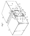
- the drawing illustrates a portion of two adjacent panels 10,12, according to the present invention.
- the panels will be substantially identical and comprise a first metal skin 14 on one face and a second metal skin 16 on the other face, the skins being adhesively bonded to an insulating core 18 formed of ROCKWOOL.
- the right hand edge of panel 10 is indicated as having an inturned bead 20 and the skin 16 having inturned bead 22.
- the opposite edges of the panels is such that the skins 14,16 are provided with a pair of spaced parallel legs 24,26.
- the insulating core 18 preferably includes two portions 28,30 extending inwardly of the spaced parallel legs 24,26 and defining therebetween a groove 32.
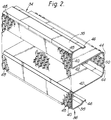
- the right hand edge of the panel 14 is shown as being provided with two joining members 34,36 which are illustrated more clearly in Figure 2. These two joining members are each of a U-shaped configuration having a shorter arm 38, a web portion 40 and a longer arm 42 having an inturned flange 44 at its free edge. It will be noted that the shorter arms 38 are each provided with a cranked flange portion 46.
- the two joining members 34,36 are connected to one another by a first expanded metal connector 48 spot welded to the web portions 40 and a second connector 50 spot welded to the flanges 44.
- a further ROCKWOOL insulating core portion 52 is positioned between the longer arms 42 and the connectors 48,50. It will be seen in Figure 1 that the cranked flange portions 46 are engaged in the inturned beads 20,22 to retain the joining members 34,36 in place.
- Figure 3 shows two forms of the inturned bead. In the upper part the inturned bead is a simple U-shaped member, as illustrated in Figure 1.
- the inturned bead has an inturned projection or projections 54 which can engage to the left, as seen in Figure 1, on the cranked flange 46 more firmly to hold the shorter arm 38 in place.
- the longer arms 42, flanges 44, connector 50 and core portion 52 form a tongue 33 engageable in groove 32, the tongue being flanked by channels 35,37 into which the legs 24,26 and the core portions 28,30 extend.
- the joining members 34,36 can be roll formed readily from sheet steel which has a far higher melting point than the aluminium of the skins 14,16.
- the connectors 48,50 are also formed of steel and as shown are formed of expanded sheet steel which is made by the conventional expanded metal technique. As alternatives the connectors 48,50 could be formed of perforated sheet steel or a steel grid. Which ever method is used, the connectors provide an adequate connection between the members 34,36 but provide a relatively small cross-sectional area for the passage of heat. The connectors 48,50, therefore, will not provide a significant heat bridge so there will be little tendency for the skins on the remote side from any fire to be raised to a sufficiently elevated temperature for them to melt.
- FIG. 4 illustrates very schematically how panels of the invention are mounted.
- a support member 60 extends vertically and has associated with it, for each panel, a bracket 62 held to the support member 60 by a screw 64.
- An arm 66 of the bracket extends into the space formed between the inturned bead 22 of the panel 10 and the leg 26 of the panel 12. The arm 66 thus retains the panels 10,12 against the support 60.
- a sealing member 68 is engaged between the bead 20 and the leg 24 on the far side of the panels.
Applications Claiming Priority (2)
| Application Number | Priority Date | Filing Date | Title |
|---|---|---|---|
| GB9208810 | 1992-04-23 | ||
| GB929208810A GB9208810D0 (en) | 1992-04-23 | 1992-04-23 | Fire resistant sandwich panel |
Publications (2)
| Publication Number | Publication Date |
|---|---|
| EP0568227A1 true EP0568227A1 (fr) | 1993-11-03 |
| EP0568227B1 EP0568227B1 (fr) | 1997-01-29 |
Family
ID=10714448
Family Applications (1)
| Application Number | Title | Priority Date | Filing Date |
|---|---|---|---|
| EP19930302998 Expired - Lifetime EP0568227B1 (fr) | 1992-04-23 | 1993-04-19 | Panneau à structure sandwich résistant au feu |
Country Status (6)
| Country | Link |
|---|---|
| EP (1) | EP0568227B1 (fr) |
| JP (1) | JP3170384B2 (fr) |
| DE (1) | DE69307765T2 (fr) |
| DK (1) | DK0568227T3 (fr) |
| ES (1) | ES2096859T3 (fr) |
| GB (1) | GB9208810D0 (fr) |
Cited By (6)
| Publication number | Priority date | Publication date | Assignee | Title |
|---|---|---|---|---|
| EP0741212A1 (fr) * | 1995-05-03 | 1996-11-06 | Norton Performance Plastics S.A. | Joint d'étanchéité pour élément de construction |
| WO1997004196A1 (fr) * | 1995-07-20 | 1997-02-06 | Cardinal Drafting, Technical & Secretarial Services Pty. Ltd. | Panneau pour paroi modulaire et a engagement reciproque |
| AU705262B2 (en) * | 1995-07-20 | 1999-05-20 | Diebold Australia Pty Ltd | An interengaging modular wall panel |
| AT409245B (de) * | 2000-01-25 | 2002-06-25 | Isosport Verbundbauteile | Bauelement sowie ein verfahren zu dessen herstellung |
| AT409279B (de) * | 1995-10-25 | 2002-07-25 | Bauelemente G M B H F J Linzme | Verbundplatte zum brandschutz |
| CN101761141A (zh) * | 2010-02-24 | 2010-06-30 | 黑龙江金鼎山建材科技开发集团有限公司 | 墙板接头 |
Families Citing this family (4)
| Publication number | Priority date | Publication date | Assignee | Title |
|---|---|---|---|---|
| KR20010110817A (ko) * | 2000-06-08 | 2001-12-15 | 장석조 | 조립식 판넬의 화재방지구조 |
| KR100460014B1 (ko) * | 2002-01-18 | 2004-12-08 | 광건티앤씨(주) | 칸막이판넬의 설치구조 |
| FI20070267L (fi) * | 2007-01-26 | 2008-07-27 | Jonmeri Yachts Oy Ab | Järjestelmä ja seinäkasetti sisäseinien ja/tai -kattojen muodostamiseksi |
| JP5897070B2 (ja) * | 2014-07-03 | 2016-03-30 | 株式会社淀川製鋼所 | 壁パネル及び壁パネルの継合構造 |
Citations (2)
| Publication number | Priority date | Publication date | Assignee | Title |
|---|---|---|---|---|
| FR2332391A1 (fr) * | 1975-11-19 | 1977-06-17 | Hunter Douglas Ind Bv | Element de paroi prefabrique |
| EP0240161A2 (fr) * | 1986-04-02 | 1987-10-07 | Hunter Douglas Industries B.V. | Panneau sandwich |
-
1992
- 1992-04-23 GB GB929208810A patent/GB9208810D0/en active Pending
-
1993
- 1993-04-19 DK DK93302998T patent/DK0568227T3/da active
- 1993-04-19 EP EP19930302998 patent/EP0568227B1/fr not_active Expired - Lifetime
- 1993-04-19 DE DE1993607765 patent/DE69307765T2/de not_active Expired - Fee Related
- 1993-04-19 ES ES93302998T patent/ES2096859T3/es not_active Expired - Lifetime
- 1993-04-21 JP JP9445693A patent/JP3170384B2/ja not_active Expired - Fee Related
Patent Citations (2)
| Publication number | Priority date | Publication date | Assignee | Title |
|---|---|---|---|---|
| FR2332391A1 (fr) * | 1975-11-19 | 1977-06-17 | Hunter Douglas Ind Bv | Element de paroi prefabrique |
| EP0240161A2 (fr) * | 1986-04-02 | 1987-10-07 | Hunter Douglas Industries B.V. | Panneau sandwich |
Cited By (8)
| Publication number | Priority date | Publication date | Assignee | Title |
|---|---|---|---|---|
| EP0741212A1 (fr) * | 1995-05-03 | 1996-11-06 | Norton Performance Plastics S.A. | Joint d'étanchéité pour élément de construction |
| FR2733778A1 (fr) * | 1995-05-03 | 1996-11-08 | Norton Performance Plastics Co | Joint d'etancheite pour element de construction |
| US5968615A (en) * | 1995-05-03 | 1999-10-19 | Norton Performance Plastics S.A. | Seal for construction element |
| WO1997004196A1 (fr) * | 1995-07-20 | 1997-02-06 | Cardinal Drafting, Technical & Secretarial Services Pty. Ltd. | Panneau pour paroi modulaire et a engagement reciproque |
| AU705262B2 (en) * | 1995-07-20 | 1999-05-20 | Diebold Australia Pty Ltd | An interengaging modular wall panel |
| AT409279B (de) * | 1995-10-25 | 2002-07-25 | Bauelemente G M B H F J Linzme | Verbundplatte zum brandschutz |
| AT409245B (de) * | 2000-01-25 | 2002-06-25 | Isosport Verbundbauteile | Bauelement sowie ein verfahren zu dessen herstellung |
| CN101761141A (zh) * | 2010-02-24 | 2010-06-30 | 黑龙江金鼎山建材科技开发集团有限公司 | 墙板接头 |
Also Published As
| Publication number | Publication date |
|---|---|
| GB9208810D0 (en) | 1992-06-10 |
| DK0568227T3 (da) | 1997-07-28 |
| ES2096859T3 (es) | 1997-03-16 |
| DE69307765D1 (de) | 1997-03-13 |
| JPH0657914A (ja) | 1994-03-01 |
| DE69307765T2 (de) | 1997-05-28 |
| EP0568227B1 (fr) | 1997-01-29 |
| JP3170384B2 (ja) | 2001-05-28 |
Similar Documents
| Publication | Publication Date | Title |
|---|---|---|
| CA1073178A (fr) | Lanterneau pour toits metalliques a nervures | |
| US3357146A (en) | Building panel splicing | |
| US4505083A (en) | Delineated ceiling grid in suspended ceiling | |
| EP0568227B1 (fr) | Panneau à structure sandwich résistant au feu | |
| US5274976A (en) | Window unit with decorative grille assembly | |
| US6314698B1 (en) | Cladding panels of sheet metal or similar material for forming a coffered ceiling and a method for assembling of such panels | |
| US4557090A (en) | Curvilinear structural insulating panel and method of making the same | |
| KR920701593A (ko) | 빌딩, 주택, 선박의 내부 및 상부 구조에서 천장과/또는 벽의 구조를 위한 스틸(steel))카세트 | |
| US5749197A (en) | Panel joint system | |
| EP0673465B1 (fr) | Petit-bois de vitrage | |
| GB2297986A (en) | A panel, e.g. a transparent roof panel. | |
| EP0026605B1 (fr) | Panneaux de construction | |
| US2988183A (en) | Mullion arrangement | |
| KR200486437Y1 (ko) | 복합창호 | |
| US3538658A (en) | Fireproof partition framework | |
| EP0064404A2 (fr) | Eléments de revêtement et leur montage | |
| KR100795062B1 (ko) | 스프링클러가지배관이 매립된 아치지붕구조 | |
| WO1997026459A1 (fr) | Structures constituees d'unites de panneaux et de pieces de liaison, procede de fabrication desdites structures | |
| EP0237651B1 (fr) | Poutrelle pour plafond suspendu, faux-plafond à résilles obtenu par ce moyen et connecteurs utilisés à cet effet | |
| JPH086408B2 (ja) | 屋根面形成用自立性構成要素 | |
| WO1986006124A1 (fr) | Panneaux de parois coupe-feu | |
| EP0726199B1 (fr) | Elément de paneau intérieur | |
| EP0900891B1 (fr) | Couverture en tôle | |
| CN214498153U (zh) | 装饰面板单元板保温一体化安装结构 | |
| JPH07293124A (ja) | 防火ガラスパネル用枠構造および取付構造 |
Legal Events
| Date | Code | Title | Description |
|---|---|---|---|
| PUAI | Public reference made under article 153(3) epc to a published international application that has entered the european phase |
Free format text: ORIGINAL CODE: 0009012 |
|
| AK | Designated contracting states |
Kind code of ref document: A1 Designated state(s): BE CH DE DK ES FR GB IT LI NL SE |
|
| 17P | Request for examination filed |
Effective date: 19940425 |
|
| 17Q | First examination report despatched |
Effective date: 19951206 |
|
| GRAG | Despatch of communication of intention to grant |
Free format text: ORIGINAL CODE: EPIDOS AGRA |
|
| GRAH | Despatch of communication of intention to grant a patent |
Free format text: ORIGINAL CODE: EPIDOS IGRA |
|
| GRAH | Despatch of communication of intention to grant a patent |
Free format text: ORIGINAL CODE: EPIDOS IGRA |
|
| GRAA | (expected) grant |
Free format text: ORIGINAL CODE: 0009210 |
|
| AK | Designated contracting states |
Kind code of ref document: B1 Designated state(s): BE CH DE DK ES FR GB IT LI NL SE |
|
| REG | Reference to a national code |
Ref country code: CH Ref legal event code: NV Representative=s name: ROTTMANN, ZIMMERMANN + PARTNER AG Ref country code: CH Ref legal event code: EP |
|
| ET | Fr: translation filed | ||
| REF | Corresponds to: |
Ref document number: 69307765 Country of ref document: DE Date of ref document: 19970313 |
|
| REG | Reference to a national code |
Ref country code: ES Ref legal event code: FG2A Ref document number: 2096859 Country of ref document: ES Kind code of ref document: T3 |
|
| PGFP | Annual fee paid to national office [announced via postgrant information from national office to epo] |
Ref country code: FR Payment date: 19970409 Year of fee payment: 5 |
|
| PGFP | Annual fee paid to national office [announced via postgrant information from national office to epo] |
Ref country code: GB Payment date: 19970410 Year of fee payment: 5 |
|
| PGFP | Annual fee paid to national office [announced via postgrant information from national office to epo] |
Ref country code: DK Payment date: 19970414 Year of fee payment: 5 |
|
| PGFP | Annual fee paid to national office [announced via postgrant information from national office to epo] |
Ref country code: SE Payment date: 19970418 Year of fee payment: 5 |
|
| ITF | It: translation for a ep patent filed |
Owner name: 0508;38MIFSTUDIO ING. ALFREDO RAIMONDI |
|
| PGFP | Annual fee paid to national office [announced via postgrant information from national office to epo] |
Ref country code: NL Payment date: 19970428 Year of fee payment: 5 |
|
| PGFP | Annual fee paid to national office [announced via postgrant information from national office to epo] |
Ref country code: CH Payment date: 19970512 Year of fee payment: 5 |
|
| PGFP | Annual fee paid to national office [announced via postgrant information from national office to epo] |
Ref country code: BE Payment date: 19970612 Year of fee payment: 5 |
|
| REG | Reference to a national code |
Ref country code: DK Ref legal event code: T3 |
|
| PLBE | No opposition filed within time limit |
Free format text: ORIGINAL CODE: 0009261 |
|
| STAA | Information on the status of an ep patent application or granted ep patent |
Free format text: STATUS: NO OPPOSITION FILED WITHIN TIME LIMIT |
|
| 26N | No opposition filed | ||
| PG25 | Lapsed in a contracting state [announced via postgrant information from national office to epo] |
Ref country code: GB Free format text: LAPSE BECAUSE OF NON-PAYMENT OF DUE FEES Effective date: 19980419 |
|
| PG25 | Lapsed in a contracting state [announced via postgrant information from national office to epo] |
Ref country code: SE Free format text: LAPSE BECAUSE OF NON-PAYMENT OF DUE FEES Effective date: 19980420 |
|
| PGFP | Annual fee paid to national office [announced via postgrant information from national office to epo] |
Ref country code: ES Payment date: 19980428 Year of fee payment: 6 |
|
| PG25 | Lapsed in a contracting state [announced via postgrant information from national office to epo] |
Ref country code: LI Free format text: LAPSE BECAUSE OF NON-PAYMENT OF DUE FEES Effective date: 19980430 Ref country code: FR Free format text: THE PATENT HAS BEEN ANNULLED BY A DECISION OF A NATIONAL AUTHORITY Effective date: 19980430 Ref country code: DK Free format text: LAPSE BECAUSE OF NON-PAYMENT OF DUE FEES Effective date: 19980430 Ref country code: CH Free format text: LAPSE BECAUSE OF NON-PAYMENT OF DUE FEES Effective date: 19980430 Ref country code: BE Free format text: LAPSE BECAUSE OF NON-PAYMENT OF DUE FEES Effective date: 19980430 |
|
| BERE | Be: lapsed |
Owner name: HUNTER DOUGLAS INDUSTRIES B.V. Effective date: 19980430 |
|
| PG25 | Lapsed in a contracting state [announced via postgrant information from national office to epo] |
Ref country code: NL Free format text: LAPSE BECAUSE OF NON-PAYMENT OF DUE FEES Effective date: 19981101 |
|
| GBPC | Gb: european patent ceased through non-payment of renewal fee |
Effective date: 19980419 |
|
| REG | Reference to a national code |
Ref country code: CH Ref legal event code: PL |
|
| NLV4 | Nl: lapsed or anulled due to non-payment of the annual fee |
Effective date: 19981101 |
|
| EUG | Se: european patent has lapsed |
Ref document number: 93302998.5 |
|
| REG | Reference to a national code |
Ref country code: FR Ref legal event code: ST |
|
| PG25 | Lapsed in a contracting state [announced via postgrant information from national office to epo] |
Ref country code: ES Free format text: LAPSE BECAUSE OF NON-PAYMENT OF DUE FEES Effective date: 19990420 |
|
| PGFP | Annual fee paid to national office [announced via postgrant information from national office to epo] |
Ref country code: DE Payment date: 19990426 Year of fee payment: 7 |
|
| REG | Reference to a national code |
Ref country code: DK Ref legal event code: EBP |
|
| PG25 | Lapsed in a contracting state [announced via postgrant information from national office to epo] |
Ref country code: DE Free format text: LAPSE BECAUSE OF NON-PAYMENT OF DUE FEES Effective date: 20010201 |
|
| REG | Reference to a national code |
Ref country code: ES Ref legal event code: FD2A Effective date: 20030203 |
|
| PG25 | Lapsed in a contracting state [announced via postgrant information from national office to epo] |
Ref country code: IT Free format text: LAPSE BECAUSE OF NON-PAYMENT OF DUE FEES;WARNING: LAPSES OF ITALIAN PATENTS WITH EFFECTIVE DATE BEFORE 2007 MAY HAVE OCCURRED AT ANY TIME BEFORE 2007. THE CORRECT EFFECTIVE DATE MAY BE DIFFERENT FROM THE ONE RECORDED. Effective date: 20050419 |