EP0567980B1 - Procédé pour la détermination des profils courbés d'arêtes - Google Patents
Procédé pour la détermination des profils courbés d'arêtes Download PDFInfo
- Publication number
- EP0567980B1 EP0567980B1 EP93106764A EP93106764A EP0567980B1 EP 0567980 B1 EP0567980 B1 EP 0567980B1 EP 93106764 A EP93106764 A EP 93106764A EP 93106764 A EP93106764 A EP 93106764A EP 0567980 B1 EP0567980 B1 EP 0567980B1
- Authority
- EP
- European Patent Office
- Prior art keywords
- laser beam
- scanning head
- curved profile
- components
- line
- Prior art date
- Legal status (The legal status is an assumption and is not a legal conclusion. Google has not performed a legal analysis and makes no representation as to the accuracy of the status listed.)
- Expired - Lifetime
Links
Images

Classifications
-
- G—PHYSICS
- G01—MEASURING; TESTING
- G01B—MEASURING LENGTH, THICKNESS OR SIMILAR LINEAR DIMENSIONS; MEASURING ANGLES; MEASURING AREAS; MEASURING IRREGULARITIES OF SURFACES OR CONTOURS
- G01B5/00—Measuring arrangements characterised by the use of mechanical techniques
- G01B5/20—Measuring arrangements characterised by the use of mechanical techniques for measuring contours or curvatures
- G01B5/205—Measuring arrangements characterised by the use of mechanical techniques for measuring contours or curvatures of turbine blades or propellers
-
- G—PHYSICS
- G01—MEASURING; TESTING
- G01B—MEASURING LENGTH, THICKNESS OR SIMILAR LINEAR DIMENSIONS; MEASURING ANGLES; MEASURING AREAS; MEASURING IRREGULARITIES OF SURFACES OR CONTOURS
- G01B11/00—Measuring arrangements characterised by the use of optical techniques
- G01B11/24—Measuring arrangements characterised by the use of optical techniques for measuring contours or curvatures
- G01B11/25—Measuring arrangements characterised by the use of optical techniques for measuring contours or curvatures by projecting a pattern, e.g. one or more lines, moiré fringes on the object
- G01B11/2545—Measuring arrangements characterised by the use of optical techniques for measuring contours or curvatures by projecting a pattern, e.g. one or more lines, moiré fringes on the object with one projection direction and several detection directions, e.g. stereo
Definitions
- the invention relates to a device for measuring curvature profiles of edges such as trailing edges of engine blades.
- US Pat. No. 4,709,156 discloses a method and a device for inspecting curved surfaces such as engine blades.
- a laser beam scans the slightly curved surface and the laser beam reflected from the surface is projected onto a detector line for detecting the curvature profile.
- This device has the disadvantage that it can only detect slightly curved surfaces.
- EP 0 379 079 A1 discloses a device for measuring curvature profiles of edges, with means for illuminating an object with a light beam with a brightness distribution that varies periodically over its cross section and for modulating the phases of the brightness distribution of the light beam.
- a light-electric detector arrangement for detecting the brightness values for a number of different modulation phases and period lengths and means for linking the detected brightness values for determining the residual phase values within the periods of the brightness distribution for defined phase positions are provided
- the means for lighting and for modulating several linear ones include parallel grids with different period lengths and are arranged on a common carrier with reference marks.
- the device comprises means which shift the linear grids in such a way that the corresponding brightness distributions of the object surface have the required phase positions.
- This known device cannot be used to measure curvature profiles of workpieces can be used that have a surface where the angle of the incident beam corresponds to the angle of the reflected beam (classic reflection law). Such shiny metallic surfaces are particularly present in turbine blades. Accordingly, the device based on light control or diffuse reflection cannot be used for "specularly reflecting" surfaces.
- Another disadvantage of the known device is that extremely precise focusing is required to measure a sharp edge, and the edge must be placed exactly in the focal plane in order to image one or two contour lines in the reception area of the camera disclosed there on the edge.
- DE 27 01 858 A1 discloses a measuring device for changes in distance, in which contour lines are generated on the object by means of interference fringes. To detect the height differences, surfaces are required that have light scattering (see FIG. 4 of the document). This known device also fails on surfaces with classic reflection.
- the object of the present invention is to provide a device which can measure curvature profiles as they occur on edges at which radii of curvature occur which are in the order of magnitude of a laser beam cross section and below.
- the device according to the invention has the advantage that with the aid of the radiation intensity matrix, the radiation intensity can be locally modulated over the radiation cross section, and thus the incident beam illuminating the curvature profile of the edge is marked continuously or in the finest stages depending on the intensity-determining pattern of the radiation intensity matrix.
- This marking can be recognized and assigned by detecting the beam reflected by the edge on the curvature profile by an arrangement for determining the curvature profile from the reflection values if the curvature profile of the edge has been illuminated at the same location with several different intensity values.
- the beam reflected on the curvature profile is advantageously detected by components arranged line by line along the curvature profile.
- a particular advantage is that with this device extremely sharp edges such as knife edges or cutting tool edges, preferably engine blade edges, can be subjected to a quality assurance check in a quick and cost-effective manner.
- the arrangement for determining the curvature profile from the reflection values preferably has a computer program with a phase shift algorithm on.
- a reflected beam section can be advantageously and reliably assigned to an illuminating beam section from three measurements with different intensity values of the radiation intensity matrix and the curvature profile point or area for this marked beam section can be determined.
- a transmission filter is preferably arranged in the laser beam as the radiation intensity matrix. This has the advantage that several different intensity values over the laser beam cross section can be set by simple mechanical means by mechanically shifting the transmission filter.
- the radiation intensity matrix preferably has intensity values which rise or fall orthogonally or obliquely to the laser beam axis, so that several or three finely graduated different intensity values, advantageously by means of two minimal local shifts in the radiation intensity matrix, mark the incident laser beam illuminating the curvature profile or finely graduated laser beam sections.
- the minimal displacement can be triggered by a micrometer screw with a stepper motor drive or preferably by a piezoceramic, which is advantageously associated with a rapid, reproducible and electronically controllable displacement.
- the radiation intensity matrix has an angle function that follows, locally adjustable, different intensity values.
- a radiation intensity matrix can advantageously be produced on a semitransparent mirror of a Michelson interferometer without any photographic or physically separated blackening or coloring, as is otherwise customary for a transmission filter.
- This preferred embodiment of the invention therefore has a modified Michelson interferometer with a semitransparent mirror, on which two coherent light-reflecting partial emitters of the laser beam are formed and are superimposed on the semi-transparent mirror by means of adjustable partial beam mirrors to form a radiation intensity matrix in the form of an interference image, with several being adjusted Intensity values a first partial beam mirror has an angular adjustment and a second partial beam mirror has a distance adjustment, preferably a piezoceramic effecting the distance adjustment.
- This embodiment of the invention has the advantage that it offers a compact design for the radiation intensity matrix and the periodicity and intensity of the intensity values can be set precisely and reproducibly in the smallest space by simple angular adjustment of the first partial beam mirror and / or minimal displacements of the piezoceramic-moving second partial beam mirror.
- the line-by-line arrangement of components can also be carried out in a flat arrangement by lining up rows of components if the laser beam permits large-area illumination.
- the laser beam is preferably optically widened in cross section while maintaining the parallelism of the laser beam.
- Means for optical expansion are preferably arranged between the laser emitter and the radiation intensity matrix and have the advantage that, in addition to a possible two-dimensional detection, the line width in particular can be increased.
- photosensitive components preferably photodiodes or photoresistance lines or video camera lines
- a computer is connected downstream as an arrangement for determining the curvature profile.
- Such an embodiment of the device has the advantage that the reflection values in the vicinity of the reflection source, the curvature profile, are converted into signals that can be evaluated electrically and can be automatically entered into the computer via movable, flexible electrical cables.
- the components are optical fibers of an optical fiber and the arrangement has photosensitive components and a computer.
- This embodiment of the invention has the advantage that the detecting components can be arranged in large numbers side by side along the curvature profile of an edge to be measured and the line can be placed around the curvature profile, since each optical fiber can be positioned individually.
- photosensitive components must be connected upstream of the computer, so that the arrangement for determining the curvature profile from the reflection values has photosensitive components and a computer.
- mirrors are preferably used as components, which first deflect the reflected laser beam line by line and reflect in a direction in which photosensitive components or optical fibers are arranged.
- This arrangement has the advantage that mirrors are more space-saving and can be positioned closer to the reflection source, the curvature profile, than photosensitive components or optical fibers.
- a preferred embodiment of the device has a scanning head in which components are arranged in rows and have a defined distance from a scanning edge and that the scanning head and scanning edge are displaceable parallel to the edge relative to the curvature profile.
- the scanning head can advantageously be guided past the curvature profile of an edge or vice versa, in that the scanning head is brought up to the scanning edge up to its scanning edge and is guided along the scanning edge along the edge to be measured.
- the runs synchronously Evaluation in the arrangement for determining the curvature profile of the edge from the reflection values.
- the edge and its curvature profile can advantageously be spatially displayed on a screen at the same time as the evaluation, so that this device can be used in quality assurance during production.
- a horizontal section of the reflected laser beam is preferably assigned to each component of the scanning head, so that the sections, when put together on the computer and the screen, result in a dimensionally accurate enlarged image of the curvature profile of the edge.
- optical fiber ends of optical fibers are arranged in the scanning head, which are arranged horizontally and at right angles to the sharp edge and thereby enclose the curvature profile in the form of an up to three-quarters of a closed ring with an opening for the incident laser beam.
- the ring is open to the curvature profile and protrudes beyond the scanning edge of the scanning head, as a result of which the curvature profile can advantageously be positioned within the ring during the measuring process, which increases the measuring accuracy and the resolution.
- the scanning head can be made extremely flat due to the use of optical fibers because the ring of optical fibers does not build up high.
- the optical fibers in the scanning head are arranged vertically and parallel to an edge and aligned with an annularly curved mirror which encloses the curvature profile as an up to three-quarter closed ring with an opening for the incident laser beam.
- This opening can be designed as a horizontal slot in the mirror surface, as a result of which advantageously only one line of the curvature profile is illuminated.
- This opening can be used as an interruption of the ring closed up to three quarters be formed, whereby the ring is divided into two parts, between which the laser beam is guided onto the curvature profile to be illuminated.
- further optical fibers are preferably arranged in the scanning head.
- the further optical fibers can be arranged line by line on both sides of the incident laser beam in the scanning head behind the ring of optical fiber ends or mirrors.
- the ring-shaped mirror is at the same time angled so that it deflects the reflected laser beam from a line-by-line horizontal direction in the direction of the optical fibers.
- the scanning head is not flat, but rather includes the curvature profile to be measured in the manner of pliers. With this vertical downward pointing arrangement, the optical fiber ends are advantageously protected against soiling and only the inexpensive ring-shaped curved mirror has to be replaced when soiled.
- a protective pane can be arranged between the mirror and the optical fiber ends, so that the scanning head can be designed as an encapsulated and dust-free unit hermetically filled with protective gas.
- the device preferably has a semiconductor laser.
- semiconductor lasers offer the advantage of a small construction volume and, on the other hand, semiconductor lasers can be designed as a semiconductor laser line in such a way that they illuminate the curvature profile line by line without upstream diaphragms or slots.
- an optical fiber bundle is arranged between the laser emitter and the scanning head. This has the advantage that only flexible leads to the scanning head are used and the scanning head can follow the course of the sharp edge in all spatial directions.
- the radiation intensity matrix is preferably arranged in the scanning head as a transmission filter or as a modified Michelson interferometer.
- the radiation intensity matrix is arranged downstream of the optical fiber bundle for the laser beam and a very compact design for the scanning head is advantageously achieved.
- Semiconductor lasers are so small in special designs that in a preferred embodiment of the invention they can be arranged in the scanning head, which advantageously avoids an optical bench or an optical fiber bundle for aligning the laser beam with the curvature profile. This simultaneously increases the complexity and compactness of the scanning head and improves the manageability of the entire device, since any readjustment or fine adjustment outside the scanning head is not necessary.
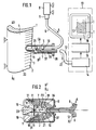
- FIG. 1 shows a device for measuring curvature profiles 1 of edges 2 and trailing edges 3 of engine blades 4 with a scanning head 5, to which a laser beam 7 of a laser emitter 8 for illuminating the curvature profile 1 is fed via an optical fiber bundle 6 in the direction of arrow A.
- an optical means 9 is arranged between the laser emitter 8 and the optical fiber bundle 6 in order to expand the laser beam 7.
- a transmission filter 10 is arranged in the scanning head 5 between the laser emitter 8 and the curvature profile 1 as a radiation intensity matrix (37) which has locally different intensity values.
- components 11 are arranged line-by-line along the curvature profile 1 of the sharp edge 2 and are operatively connected via an electrical cable bundle 12 to an arrangement 13 for determining the curvature profile 1 from the reflection values of the laser beam 7 at the edge 2.
- These components 11 can be photoresistor or photodiode or video camera lines or line-by-line optical fibers.
- the arrangement consists of a converter 14 which converts the optical or electrical signals of the components 11 into input signals for a computer 15.
- this computer In order to determine the curvature profile 1 from the reflection values of the laser beam 7 at the edge 2, this computer has a computer program with a phase shift algorithm. The result is shown in a display unit 16.
- This display unit 16 can be equipped with a screen, a printer and / or a plotter for graphically or numerically documenting the profile of the curvature.
- the scanning head 5 was moved along the sharp edge 2 in the direction of arrow B or C and a three-dimensional one Image 17 of the curvature profiles 1 generated on the display unit 16.
- the edge 2 to be measured can also be guided along the scanning head 5 in the arrow directions E or D in order to achieve such a measurement of the curvature profiles 1.
- FIG. 2 shows the scanning head 5 from FIG. 1 in cross section.
- the optical fiber bundle 6 directs the incident laser beam onto the transmission filter 10, which is arranged between the laser emitter (item 8, FIG. 1) and the curvature profile 1.
- the transmission filter 10 in the scanning head (5) is mechanically adjusted into, for example, 3 different positions by moving it in the arrow directions F or G. This adjustment mechanism is driven by a piezoceramic.
- the scanning head 5 has a scanning edge 18.
- the line-by-line components 11 for detecting the reflection values protrude beyond this scanning edge 18 so that they enclose the curvature profile 1 on both sides.
- guide springs 19 are slidably arranged on the side of the measuring object 20.
- Signal fibers 21 of the components 11 are combined to form a line bundle 12, which establishes the operative connection to the arrangement 13.
- FIG. 3 shows a device with a scanning head 5 which has a modified Michelson interferrometer 22 as an integral part of the spacer.
- Optical means for expanding the laser beam can be built into the Michelson interferometer or, as in this example, optical means 9 for expanding the laser beam are connected downstream of the laser emitter 8.
- the laser emitter 8 sends a laser beam 7 via the deflection mirror via the optical fiber bundle 6 23 onto a semitransparent mirror 24, which serves as a radiation intensity matrix.
- the semi-transparent mirror 24 generates two coherent partial beams 25 and 26, which are reflected by two partial beam mirrors 27 and 28 onto the semi-transparent mirror 24 and form an interference matrix as a radiation intensity matrix by superposition at an angle H in the plane of the semi-transparent mirror 24.
- the different intensity values required for the measurement of the curvature profile can be reproducibly set on the one hand by different angles H on the partial beam mirror 28 or by minimal displacements of the partial beam mirror 27 in the arrow direction K. Piezoceramics are used in this example to drive the adjustments of the partial mirrors.
- the modulated laser beam 29 illuminates the curvature profile 1.
- the reflected laser beams are deflected into the vertical by a mirror 30 and fed from the optical fiber ends 31 arranged above the mirror 30 via an optical fiber bundle 32 to the arrangement 13 for determining the curvature profile 1 from the reflection data.
- the light signal is first converted into a computer input signal in a converter 14, which in this example has a photosensitive video camera line, and then fed to the computer 15, which supplies a display unit for mapping the curvature profile 1 with evaluated measurement data.
- Fig. 4 shows the scanning head 5 of Fig. 3 in plan view.
- the scanning head 5 has a modified Michelson interferrometer 22 and an annular mirror 30.
- the mirror 30 has the shape of a ring 39 which is closed up to three-quarters of its circumference.
- the reflector of the mirror 35 is angled, for example, at 45 ° relative to the row plane, so that the reflected laser beams are redirected to the vertical.
- this mirror 30 there is an opening 33 through which the laser beam 29 can illuminate the curvature profile 1 with modulated light.
- a scanning edge 18 is arranged in the scanning head 5 in such a way that the ring mirror 33 which is open towards the measurement object 20 largely encloses the curvature profile 1.
- further optical fiber lines 34 and 35 are arranged on both sides of the incident modulated laser beam 29. All optical fibers 36 are combined in the scanning head 5 to form an optical fiber bundle 32.
Claims (18)
- Dispositif pour mesurer ou faire le relevé de profils de courbure d'arêtes tels que les bords de fuite de pales ou d'aubes de moteurs à l'aide de générateurs laser, comprenant un filtre de transmission (10) ou un interféromètre (22), réglable, prévu entre le profil de courbure (1) et le générateur de faisceau laser (8), et qui donne des valeurs d'intensité croissantes ou décroissantes transversalement à l'axe (50) du laser pour marquer des segments du faisceau laser permettant une association biunivoque entre les segments incidents sous un certain angle et les segments réfléchis sous un angle correspondant, transversalement à l'axe (50) du laser, ainsi que des composants (11) coopérant pour détecter les valeurs de réflexion des segments du faisceau laser (7) le long du profil de courbure (1) de l'arête (2), en étant prévus ligne par ligne dans la tête de détection (5), et le profil de courbure (1) étant entouré sur trois quarts, par un anneau fermé (39) ayant une ouverture (33) pour le faisceau laser incident et un dispositif (13) pour déterminer le profil de courbure (1) à partir des valeurs de réflexion.
- Dispositif selon la revendication 1,
caractérisé en ce que
les composants (11) sont des composants photosensibles, de préférence des lignes de photodiodes ou de photorésistances ou des lignes de caméras vidéo, et le dispositif (13) comporte un calculateur (15) pour déterminer le profil de courbure (1). - Dispositif selon l'une des revendications 1 ou 2,
caractérisé en ce que
les composants (11) sont les fibres optiques (36) d'un guide de lumière (32) et le dispositif (13) comporte un convertisseur (14) à composants photosensibles et calculateur (15). - Dispositif selon l'une des revendications 1 à 3,
caractérisé en ce que
les composants (11) sont des miroirs (30) réfléchissant ligne par ligne pour dévier le faisceau laser réfléchi (7) en direction des fibres optiques (36) en aval, ou des composants photosensibles. - Dispositif selon l'une des revendications 1 à 4,
caractérisé en ce que
la disposition pour déterminer le profil de courbure (1) à partir des valeurs de réflexion comprend un programme de calcul avec un algorithme de déphasage. - Dispositif selon l'une des revendications 1 à 5,
caractérisé en ce que
le filtre de transmission (10) ou l'interféromètre (22) présente des valeurs d'intensité localement différentes suivant une fonction angulaire. - Dispositif selon l'une des revendications 1 à 6,
caractérisé en ce que
pour régler plusieurs valeurs de transmission, le filtre de transmission (10) ou l'interféromètre (22) coopère avec une céramique piézo-électrique. - Dispositif selon l'une des revendications 1 à 7,
caractérisé en ce que
l'interféromètre (22) comporte un miroir semi-transparent (24) d'un interféromètre de Michelson, modifié, formant deux générateurs de faisceaux partiels du faisceau laser, donnant des faisceaux réfléchis de lumière cohérente et qui se combinent à l'aide d'un miroir à faisceaux partiels réglables (27, 28) en une matrice d'intensité de rayonnement sous la forme d'une image d'interférences sur le miroir semi-transparent (24), et pour le réglage de plusieurs valeurs d'intensité, un premier miroir à faisceau partiel (28) offre un réglage d'angle et un second miroir à faisceau partiel (27) comporte une piézo-céramique. - Dispositif selon l'une des revendications 1 à 8,
caractérisé en ce qu'
il comporte une tête de détection (5) pour la détection dans l'espace du profil de courbure (1), tête dans laquelle sont prévus ligne par ligne des composants (11) qui ont une distance déterminée par rapport à une arête de détection (18), la tête de détection (5) avec l'arête de détection (18) étant montée de manière mobile par rapport au profil de courbure (1), parallèlement à l'arête (2). - Dispositif selon l'une des revendications 1 à 9,
caractérisé en ce qu'
à chaque composant (11) de la tête de détection (5) est associé un segment horizontal du faisceau laser réfléchi (7). - Dispositif selon l'une des revendications 1 à 10,
caractérisé en ce que
les composants (11) sont montés dans la tête de détection (5) pour transmettre le segment de faisceau laser réfléchi, et des extrémités de fibres optiques (31) des fibres (36) sont prévues dans une direction perpendiculaire par rapport à l'arête (2). - Dispositif selon l'une des revendications 1 à 11,
caractérisé en ce que
les fibres optiques (36) de la tête de détection (5, 38) sont réparties parallèlement à l'arête (2) et sont alignées vers un miroir (30) cintré en forme d'anneau, entourant le profil de courbure suivant un anneau fermé (39) correspondant à trois quarts et ayant une ouverture (33) pour le faisceau laser incident (29), le montage étant à l'équerre pour que le faisceau laser réfléchi soit dévié d'une direction horizontale, ligne par ligne, vers la direction verticale des fibres optiques (36). - Dispositif selon l'une des revendications 1 à 12,
caractérisé en ce que
d'autres fibres optiques (40) sont prévues dans la tête de détection (5, 38) pour détecter la composante de fibres optiques réfléchie par l'ouverture (33) du faisceau laser incident (7). - Dispositif selon l'une des revendications 1 à 13,
caractérisé en ce que
le générateur laser (8) est un laser à semi-conducteur. - Dispositif selon l'une des revendications 1 à 14,
caractérisé par
un moyen d'étalement optique de faisceau laser (9) prévu entre le faisceau laser (8) et le filtre de transmission (10) ou l'interféromètre (22). - Dispositif selon l'une des revendications 1 à 15,
caractérisé par
un faisceau de fibres optiques (6) prévu entre le générateur laser (8) et la tête de détection (5, 38). - Dispositif selon l'une des revendications 1 à 16,
caractérisé en ce que
le laser à semi-conducteur (8) est prévu dans la tête de détection (5, 38). - Dispositif selon l'une des revendications 1 à 17,
caractérisé en ce qu'
un interféromètre de Michelson (23), modifié, est prévu dans la tête de détection (5, 38).
Applications Claiming Priority (2)
| Application Number | Priority Date | Filing Date | Title |
|---|---|---|---|
| DE4213909 | 1992-04-28 | ||
| DE4213909A DE4213909A1 (de) | 1992-04-28 | 1992-04-28 | Vorrichtung zur vermessung von kruemmungsprofilen von kanten |
Publications (2)
| Publication Number | Publication Date |
|---|---|
| EP0567980A1 EP0567980A1 (fr) | 1993-11-03 |
| EP0567980B1 true EP0567980B1 (fr) | 1997-07-09 |
Family
ID=6457635
Family Applications (1)
| Application Number | Title | Priority Date | Filing Date |
|---|---|---|---|
| EP93106764A Expired - Lifetime EP0567980B1 (fr) | 1992-04-28 | 1993-04-27 | Procédé pour la détermination des profils courbés d'arêtes |
Country Status (3)
| Country | Link |
|---|---|
| EP (1) | EP0567980B1 (fr) |
| AT (1) | ATE155239T1 (fr) |
| DE (2) | DE4213909A1 (fr) |
Families Citing this family (6)
| Publication number | Priority date | Publication date | Assignee | Title |
|---|---|---|---|---|
| US5500737A (en) * | 1993-07-21 | 1996-03-19 | General Electric Company | Method for measuring the contour of a surface |
| EP0699890A1 (fr) * | 1994-08-02 | 1996-03-06 | General Electric Company | Un appareil pour mesurer le contour d'une surface |
| DE10162279A1 (de) * | 2001-04-22 | 2002-10-31 | Gunther Roeder | Verfahren und Vorrichtung zur Bestimmung der Höhe eines Grates |
| DE102015214995A1 (de) | 2015-08-06 | 2017-02-09 | MTU Aero Engines AG | Vorrichtung und Verfahren zur Herstellung oder Reparatur eines dreidimensionalen Objekts |
| CN106643619B (zh) * | 2017-02-10 | 2022-10-14 | 大连交通大学 | 螺旋桨叶片厚度测量装置、测量系统及测量方法 |
| CN107036559A (zh) * | 2017-05-31 | 2017-08-11 | 天津大学 | 一种曲面斜率的测量方法 |
Citations (1)
| Publication number | Priority date | Publication date | Assignee | Title |
|---|---|---|---|---|
| DE3803451A1 (de) * | 1988-02-05 | 1989-08-17 | Bochumer Eisen Heintzmann | Verfahren zur herstellung eines optischen messstrahlenaufnehmers fuer eine vorrichtung zur beruehrungslosen optischen entfernungsmessung |
Family Cites Families (12)
| Publication number | Priority date | Publication date | Assignee | Title |
|---|---|---|---|---|
| DE1926979A1 (de) * | 1968-05-27 | 1969-12-04 | Hawker Siddeley Dynamics Ltd | Verfahren zur Pruefung von Anschliffflaechen eines Werkstueckes,insbesondere einer Rasierklinge |
| DE2412359A1 (de) * | 1974-03-14 | 1975-09-25 | Dornier System Gmbh | Verfahren und geraet zur beruehrungslosen vermessung von objektkonturen |
| GB1540075A (en) * | 1975-05-09 | 1979-02-07 | Rolls Royce | Apparatus and a method of determining the shape of a surface |
| GB1521351A (en) * | 1976-01-19 | 1978-08-16 | Nat Res Dev | Methods and apparatus for measuring variations in distance to a surface |
| US4657394A (en) * | 1984-09-14 | 1987-04-14 | New York Institute Of Technology | Apparatus and method for obtaining three dimensional surface contours |
| US4849643A (en) * | 1987-09-18 | 1989-07-18 | Eaton Leonard Technologies | Optical probe with overlapping detection fields |
| GB8724527D0 (en) * | 1987-10-20 | 1987-11-25 | Cruickshank J S | Projection apparatus |
| US4830485A (en) * | 1987-11-23 | 1989-05-16 | General Electric Company | Coded aperture light detector for three dimensional camera |
| DE3817561A1 (de) * | 1988-05-24 | 1989-11-30 | Fraunhofer Ges Forschung | Vorrichtung zur erzeugung eines projizierten objektgitters |
| CH677972A5 (fr) * | 1989-01-17 | 1991-07-15 | Kern & Co Ag | |
| EP0387521A3 (fr) * | 1989-02-28 | 1991-02-06 | Siemens Aktiengesellschaft | Capteur optique de distances |
| DE3933994A1 (de) * | 1989-10-11 | 1991-05-08 | Kaltenbach & Voigt | Optische sonde zur absoluten 3-dimensionalen vermessung von einzelzaehnen und zahngruppen in der mundhoehle |
-
1992
- 1992-04-28 DE DE4213909A patent/DE4213909A1/de not_active Withdrawn
-
1993
- 1993-04-27 EP EP93106764A patent/EP0567980B1/fr not_active Expired - Lifetime
- 1993-04-27 AT AT93106764T patent/ATE155239T1/de not_active IP Right Cessation
- 1993-04-27 DE DE59306856T patent/DE59306856D1/de not_active Expired - Fee Related
Patent Citations (1)
| Publication number | Priority date | Publication date | Assignee | Title |
|---|---|---|---|---|
| DE3803451A1 (de) * | 1988-02-05 | 1989-08-17 | Bochumer Eisen Heintzmann | Verfahren zur herstellung eines optischen messstrahlenaufnehmers fuer eine vorrichtung zur beruehrungslosen optischen entfernungsmessung |
Also Published As
| Publication number | Publication date |
|---|---|
| DE59306856D1 (de) | 1997-08-14 |
| DE4213909A1 (de) | 1993-11-04 |
| ATE155239T1 (de) | 1997-07-15 |
| EP0567980A1 (fr) | 1993-11-03 |
Similar Documents
| Publication | Publication Date | Title |
|---|---|---|
| EP1373827B1 (fr) | Appareil de mesure | |
| DE112005000639B4 (de) | Vorrichtung und Verfahren zur kombinierten interferometrischen und abbildungsbasierten Geometrieerfassung, insbesondere in der Mikrosystemtechnik | |
| DE102006021557B3 (de) | Vorrichtung und Verfahren zur kombinierten interferometrischen und abbildungsbasierten Geometrieerfassung, insbesondere in der Mikrosystemtechnik | |
| DE102017128158A1 (de) | Abstandsmessungsvorrichtung und Verfahren zur Messung von Abständen | |
| DE10154125A1 (de) | Messverfahren und Messsystem zur Vermessung der Abbildungsqualität eines optischen Abbildunsgssystems | |
| DE3642051A1 (de) | Verfahren zur dreidimensionalen informationsverarbeitung und vorrichtung zum erhalten einer dreidimensionalen information ueber ein objekt | |
| EP0932816A1 (fr) | Procede et dispositif pour mesurer le trace de surfaces reflechissantes | |
| DE4343076A1 (de) | Vorrichtung zum photothermischen Prüfen einer Oberfläche | |
| DE3930632A1 (de) | Verfahren zur direkten phasenmessung von strahlung, insbesondere lichtstrahlung, und vorrichtung zur durchfuehrung dieses verfahrens | |
| EP1354234B1 (fr) | Systeme optique et procede d'activation et de mesure de la fluorescence sur ou dans des echantillons traites avec des colorants fluorescents | |
| DE3024027A1 (de) | Optisches mikrometermessgeraet | |
| WO2013064395A1 (fr) | Dispositif permettant de déterminer de façon optique la géométrie de surface d'un échantillon tridimensionnel | |
| EP0567980B1 (fr) | Procédé pour la détermination des profils courbés d'arêtes | |
| DE102019201272B4 (de) | Vorrichtung, Vermessungssystem und Verfahren zur Erfassung einer zumindest teilweise spiegelnden Oberfläche unter Verwendung zweier Spiegelungsmuster | |
| DE4039318A1 (de) | Einrichtung zur erfassung der hoehenlage einer laserbearbeitungsvorrichtung bezueglich eines werkstuecks | |
| DE3322714C2 (de) | Optische Abstandsmeßvorrichtung | |
| DE3831267A1 (de) | Optischer messfuehler | |
| DE1814328A1 (de) | Vorrichtung zur Bestimmung des Profils einer Flaeche | |
| DE4113279C2 (de) | Konfokales optisches Rastermikroskop | |
| EP2276999B1 (fr) | Agencement optique d'éclairage d'un objet de mesure et agencement interférométrique pour le mesurage de surfaces d'un objet de mesure | |
| DE3020044C2 (fr) | ||
| DE60020282T2 (de) | Illuminator für ein optisches messinstrument | |
| EP0567981B1 (fr) | Procédé pour la mensuration des profils courbés d'arêtes | |
| DE3446354C2 (fr) | ||
| DE10146945A1 (de) | Meßanordnung und Meßverfahren |
Legal Events
| Date | Code | Title | Description |
|---|---|---|---|
| PUAI | Public reference made under article 153(3) epc to a published international application that has entered the european phase |
Free format text: ORIGINAL CODE: 0009012 |
|
| AK | Designated contracting states |
Kind code of ref document: A1 Designated state(s): AT CH DE FR GB IT LI |
|
| 17P | Request for examination filed |
Effective date: 19940322 |
|
| 17Q | First examination report despatched |
Effective date: 19951113 |
|
| GRAG | Despatch of communication of intention to grant |
Free format text: ORIGINAL CODE: EPIDOS AGRA |
|
| GRAH | Despatch of communication of intention to grant a patent |
Free format text: ORIGINAL CODE: EPIDOS IGRA |
|
| GRAH | Despatch of communication of intention to grant a patent |
Free format text: ORIGINAL CODE: EPIDOS IGRA |
|
| GRAA | (expected) grant |
Free format text: ORIGINAL CODE: 0009210 |
|
| AK | Designated contracting states |
Kind code of ref document: B1 Designated state(s): AT CH DE FR GB IT LI |
|
| REF | Corresponds to: |
Ref document number: 155239 Country of ref document: AT Date of ref document: 19970715 Kind code of ref document: T |
|
| REG | Reference to a national code |
Ref country code: CH Ref legal event code: EP |
|
| ET | Fr: translation filed | ||
| GBT | Gb: translation of ep patent filed (gb section 77(6)(a)/1977) |
Effective date: 19970714 |
|
| REF | Corresponds to: |
Ref document number: 59306856 Country of ref document: DE Date of ref document: 19970814 |
|
| PLBE | No opposition filed within time limit |
Free format text: ORIGINAL CODE: 0009261 |
|
| STAA | Information on the status of an ep patent application or granted ep patent |
Free format text: STATUS: NO OPPOSITION FILED WITHIN TIME LIMIT |
|
| 26N | No opposition filed | ||
| PG25 | Lapsed in a contracting state [announced via postgrant information from national office to epo] |
Ref country code: FR Free format text: LAPSE BECAUSE OF NON-PAYMENT OF DUE FEES Effective date: 20011231 |
|
| REG | Reference to a national code |
Ref country code: GB Ref legal event code: IF02 |
|
| REG | Reference to a national code |
Ref country code: FR Ref legal event code: ST |
|
| REG | Reference to a national code |
Ref country code: FR Ref legal event code: D3 |
|
| PGFP | Annual fee paid to national office [announced via postgrant information from national office to epo] |
Ref country code: CH Payment date: 20050412 Year of fee payment: 13 |
|
| PGFP | Annual fee paid to national office [announced via postgrant information from national office to epo] |
Ref country code: AT Payment date: 20050414 Year of fee payment: 13 |
|
| PG25 | Lapsed in a contracting state [announced via postgrant information from national office to epo] |
Ref country code: AT Free format text: LAPSE BECAUSE OF NON-PAYMENT OF DUE FEES Effective date: 20060427 |
|
| PG25 | Lapsed in a contracting state [announced via postgrant information from national office to epo] |
Ref country code: LI Free format text: LAPSE BECAUSE OF NON-PAYMENT OF DUE FEES Effective date: 20060430 Ref country code: CH Free format text: LAPSE BECAUSE OF NON-PAYMENT OF DUE FEES Effective date: 20060430 |
|
| REG | Reference to a national code |
Ref country code: CH Ref legal event code: PL |
|
| PGFP | Annual fee paid to national office [announced via postgrant information from national office to epo] |
Ref country code: DE Payment date: 20080418 Year of fee payment: 16 |
|
| PGFP | Annual fee paid to national office [announced via postgrant information from national office to epo] |
Ref country code: IT Payment date: 20080426 Year of fee payment: 16 |
|
| PGFP | Annual fee paid to national office [announced via postgrant information from national office to epo] |
Ref country code: FR Payment date: 20080412 Year of fee payment: 16 |
|
| PGFP | Annual fee paid to national office [announced via postgrant information from national office to epo] |
Ref country code: GB Payment date: 20080421 Year of fee payment: 16 |
|
| GBPC | Gb: european patent ceased through non-payment of renewal fee |
Effective date: 20090427 |
|
| REG | Reference to a national code |
Ref country code: FR Ref legal event code: ST Effective date: 20091231 |
|
| PG25 | Lapsed in a contracting state [announced via postgrant information from national office to epo] |
Ref country code: DE Free format text: LAPSE BECAUSE OF NON-PAYMENT OF DUE FEES Effective date: 20091103 |
|
| PG25 | Lapsed in a contracting state [announced via postgrant information from national office to epo] |
Ref country code: GB Free format text: LAPSE BECAUSE OF NON-PAYMENT OF DUE FEES Effective date: 20090427 |
|
| PG25 | Lapsed in a contracting state [announced via postgrant information from national office to epo] |
Ref country code: IT Free format text: LAPSE BECAUSE OF NON-PAYMENT OF DUE FEES Effective date: 20090427 |
|
| PG25 | Lapsed in a contracting state [announced via postgrant information from national office to epo] |
Ref country code: FR Free format text: LAPSE BECAUSE OF NON-PAYMENT OF DUE FEES Effective date: 20090430 |