EP0567167B1 - Verfahren zum Kühlen heisser Feststoffe im Wirbelbett - Google Patents
Verfahren zum Kühlen heisser Feststoffe im Wirbelbett Download PDFInfo
- Publication number
- EP0567167B1 EP0567167B1 EP93200703A EP93200703A EP0567167B1 EP 0567167 B1 EP0567167 B1 EP 0567167B1 EP 93200703 A EP93200703 A EP 93200703A EP 93200703 A EP93200703 A EP 93200703A EP 0567167 B1 EP0567167 B1 EP 0567167B1
- Authority
- EP
- European Patent Office
- Prior art keywords
- solids
- cooling
- bed
- fluidized bed
- cooling chamber
- Prior art date
- Legal status (The legal status is an assumption and is not a legal conclusion. Google has not performed a legal analysis and makes no representation as to the accuracy of the status listed.)
- Expired - Lifetime
Links
- 238000001816 cooling Methods 0.000 title claims description 56
- 238000000034 method Methods 0.000 title claims description 12
- 239000011343 solid material Substances 0.000 title 1
- 239000007787 solid Substances 0.000 claims description 52
- 239000012809 cooling fluid Substances 0.000 claims description 13
- 238000005192 partition Methods 0.000 claims description 8
- 239000007789 gas Substances 0.000 description 26
- 239000000498 cooling water Substances 0.000 description 5
- 239000012530 fluid Substances 0.000 description 5
- 238000011144 upstream manufacturing Methods 0.000 description 3
- IJGRMHOSHXDMSA-UHFFFAOYSA-N Atomic nitrogen Chemical compound N#N IJGRMHOSHXDMSA-UHFFFAOYSA-N 0.000 description 2
- 230000001914 calming effect Effects 0.000 description 2
- 230000000052 comparative effect Effects 0.000 description 2
- 238000010586 diagram Methods 0.000 description 2
- 239000007788 liquid Substances 0.000 description 2
- XLYOFNOQVPJJNP-UHFFFAOYSA-N water Substances O XLYOFNOQVPJJNP-UHFFFAOYSA-N 0.000 description 2
- 239000010883 coal ash Substances 0.000 description 1
- 238000004581 coalescence Methods 0.000 description 1
- 238000005243 fluidization Methods 0.000 description 1
- 230000017525 heat dissipation Effects 0.000 description 1
- 229910052757 nitrogen Inorganic materials 0.000 description 1
- 239000003921 oil Substances 0.000 description 1
- 150000003839 salts Chemical class 0.000 description 1
Images
Classifications
-
- B—PERFORMING OPERATIONS; TRANSPORTING
- B01—PHYSICAL OR CHEMICAL PROCESSES OR APPARATUS IN GENERAL
- B01J—CHEMICAL OR PHYSICAL PROCESSES, e.g. CATALYSIS OR COLLOID CHEMISTRY; THEIR RELEVANT APPARATUS
- B01J8/00—Chemical or physical processes in general, conducted in the presence of fluids and solid particles; Apparatus for such processes
- B01J8/18—Chemical or physical processes in general, conducted in the presence of fluids and solid particles; Apparatus for such processes with fluidised particles
- B01J8/24—Chemical or physical processes in general, conducted in the presence of fluids and solid particles; Apparatus for such processes with fluidised particles according to "fluidised-bed" technique
- B01J8/36—Chemical or physical processes in general, conducted in the presence of fluids and solid particles; Apparatus for such processes with fluidised particles according to "fluidised-bed" technique with fluidised bed through which there is an essentially horizontal flow of particles
-
- B—PERFORMING OPERATIONS; TRANSPORTING
- B01—PHYSICAL OR CHEMICAL PROCESSES OR APPARATUS IN GENERAL
- B01J—CHEMICAL OR PHYSICAL PROCESSES, e.g. CATALYSIS OR COLLOID CHEMISTRY; THEIR RELEVANT APPARATUS
- B01J8/00—Chemical or physical processes in general, conducted in the presence of fluids and solid particles; Apparatus for such processes
- B01J8/18—Chemical or physical processes in general, conducted in the presence of fluids and solid particles; Apparatus for such processes with fluidised particles
- B01J8/1836—Heating and cooling the reactor
-
- B—PERFORMING OPERATIONS; TRANSPORTING
- B01—PHYSICAL OR CHEMICAL PROCESSES OR APPARATUS IN GENERAL
- B01J—CHEMICAL OR PHYSICAL PROCESSES, e.g. CATALYSIS OR COLLOID CHEMISTRY; THEIR RELEVANT APPARATUS
- B01J8/00—Chemical or physical processes in general, conducted in the presence of fluids and solid particles; Apparatus for such processes
- B01J8/18—Chemical or physical processes in general, conducted in the presence of fluids and solid particles; Apparatus for such processes with fluidised particles
- B01J8/1845—Chemical or physical processes in general, conducted in the presence of fluids and solid particles; Apparatus for such processes with fluidised particles with particles moving upwards while fluidised
-
- B—PERFORMING OPERATIONS; TRANSPORTING
- B01—PHYSICAL OR CHEMICAL PROCESSES OR APPARATUS IN GENERAL
- B01J—CHEMICAL OR PHYSICAL PROCESSES, e.g. CATALYSIS OR COLLOID CHEMISTRY; THEIR RELEVANT APPARATUS
- B01J8/00—Chemical or physical processes in general, conducted in the presence of fluids and solid particles; Apparatus for such processes
- B01J8/18—Chemical or physical processes in general, conducted in the presence of fluids and solid particles; Apparatus for such processes with fluidised particles
- B01J8/24—Chemical or physical processes in general, conducted in the presence of fluids and solid particles; Apparatus for such processes with fluidised particles according to "fluidised-bed" technique
- B01J8/26—Chemical or physical processes in general, conducted in the presence of fluids and solid particles; Apparatus for such processes with fluidised particles according to "fluidised-bed" technique with two or more fluidised beds, e.g. reactor and regeneration installations
-
- F—MECHANICAL ENGINEERING; LIGHTING; HEATING; WEAPONS; BLASTING
- F28—HEAT EXCHANGE IN GENERAL
- F28D—HEAT-EXCHANGE APPARATUS, NOT PROVIDED FOR IN ANOTHER SUBCLASS, IN WHICH THE HEAT-EXCHANGE MEDIA DO NOT COME INTO DIRECT CONTACT
- F28D13/00—Heat-exchange apparatus using a fluidised bed
-
- B—PERFORMING OPERATIONS; TRANSPORTING
- B01—PHYSICAL OR CHEMICAL PROCESSES OR APPARATUS IN GENERAL
- B01J—CHEMICAL OR PHYSICAL PROCESSES, e.g. CATALYSIS OR COLLOID CHEMISTRY; THEIR RELEVANT APPARATUS
- B01J2208/00—Processes carried out in the presence of solid particles; Reactors therefor
- B01J2208/00008—Controlling the process
- B01J2208/00017—Controlling the temperature
- B01J2208/00106—Controlling the temperature by indirect heat exchange
- B01J2208/00115—Controlling the temperature by indirect heat exchange with heat exchange elements inside the bed of solid particles
- B01J2208/00132—Tubes
Definitions
- the invention relates to a method for cooling hot, granular solids under superatmospheric pressure up to 50 bar in a first cooling chamber and a second cooling chamber, between which there is a partition wall which has an opening connecting the two cooling chambers in the lower region, the solids to be cooled form fluidized beds in both cooling chambers, which are in contact with cooling devices arranged in both chambers, the solids to be cooled being passed through a solids inlet on top of the fluidized bed of the second cooling chamber, the solids in the second cooling chamber predominantly downward in the vertical direction Opening in the partition leads and then the solids in the first cooling chamber predominantly in the vertical direction upwards to a solids drain, and wherein fluidizing gas is introduced into the lower region of the two fluidized beds and through which a cooling fluid flows dissipates heat indirectly.
- a method of this type and a device suitable therefor are known from EP-A-0478418.
- the invention has for its object to improve the method and to reduce operating costs. In particular, intensive cooling of the solids and a low requirement for fluidizing gas are sought.
- the two fluidized beds have a bed height of 3 to 20 m and a ratio of the bed height to the average bed width of 3: 1 to 10: 1, that the pressure in both fluidized beds 5 to 50 bar is that the cooling devices extend at least half the height of the associated fluidized bed, that the cooling fluid flows in both cooling devices in cocurrent or countercurrent to the vertical movement of the solids and that the temperature differences of the solids between the lower and upper range of the Both fluidized beds must be at least 200 ° C.
- the fluidization state in the fluidized beds is that of a stationary fluidized bed.
- Fluidized bed coolers that work under atmospheric conditions or pressures below 2 bar can only be operated with a low bed height due to disturbing bubble coalescence.
- the bed height is at least 3 m.
- the ratio of the bed height to the average bed width is 3: 1 to 10: 1.
- the average bed width is calculated from the mean of the largest and smallest width, measured on a horizontal plane through the fluidized bed, if the cross section is not circular . If the bed cross-section changes over the bed height, the average bed width results from the average of the respective average values of different bed cross-sections, which are at equal intervals from e.g. 50 cm at different heights through the fluidized bed.
- the solids to be cooled initially move downwards and upwards towards the fluidized beds. Intensive mixing of the solids in the vertical direction is not to be expected, so that a profile of the solids temperature is established above the bed height. Therefore, the cooling fluid flowing up or down in the fluidized bed of the cooling device can be used to set a consistent countercurrent or also a consistent direct current between the cooling fluid and solids. This leads to a high heat transfer from the solids to the cooling fluid, particularly in the case of countercurrent flow.
- the direct current flow has advantages if the solid is to be cooled rapidly immediately after entering the fluidized bed or if the cooling fluid is to be evaporated when the solid flow is directed upwards.
- the cooling fluid can be a liquid or a gaseous or vaporous fluid.
- Known cooling liquids which can be used are, for example, water, oils or molten salts, and furthermore, for example, water vapor or a wide variety of gases (for example nitrogen) can be used to remove the heat.
- the hot solids are usually brought in at temperatures of 400 to 1200 ° C. In the case of the high fluidized beds with a small cross-sectional area designed according to the invention, the need for fluidizing gas is relatively low. 300 to 7500 Nm 3 of fluidizing gas are sufficient per m 3 of fluidized bed volume and per hour.
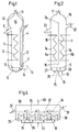
- the device of FIG. 1 has a high, slim cooling chamber (1) which has a solids inlet (2) and a solids outlet (3).
- a fluidized bed (not shown) made of granular solids which are introduced through the line (4) during operation.
- the fluidized bed extends from a nozzle grate (5) to the outlet (3) and it surrounds the coiled line of a cooling device (6), through which a cooling fluid is passed for heat dissipation.
- Fluidizing gas is fed through line (8) and first reaches a distribution chamber (9) before it rises up through the nozzle grate (5) and fluidizes the fluidized bed. After exiting the fluidized bed, the fluidizing gases first flow into an enlarged calming space (1) and leave the cooling device through the exhaust (11) the other treatment facilities, not shown, for example dedusting, can be connected.
- the cooling chamber (1) can be designed such that the fluidized bed located therein has a bed height of 3 to 20 m.
- the granular solids to be cooled move from the solids inlet (2) under the action of the fluidizing gas, e.g. Air up in the cooling chamber (1) and leave the fluidized bed through the drain (3).
- the fluidizing gas e.g. Air up in the cooling chamber (1) and leave the fluidized bed through the drain (3).
- the cooling fluid flowing in the cooling device (6) can be conducted to the solids in cocurrent or countercurrent.
- a line (13) can be provided in the feed (2) for feeding a controlling gas.
- the cooling chamber (1) and the calming space (10) are enclosed by a pressure-resistant container (12).
- the cooling device of FIG. 2 which is suitable for the method according to the invention, shows a first cooling chamber (1a) and a second cooling chamber (1b).
- a partition (7) is located between the cooling chambers (1a) and (1b), an opening (15) remaining between the nozzle grate (5) and the lower edge of the partition (7).
- a pressure-resistant housing (16) encloses the cooling chambers, it has a solids inlet (22) and a solids outlet (23).
- the upper edge (7a) of the partition (7) is higher than the inlet (22) and the outlet (23). Eddy gases leave the housing through the trigger (11).
- the hot solids which are brought in through the inlet (22), first reach the second cooling chamber (1b), in which there is a fluidized bed, which is referred to here as an "upstream fluidized bed", which is brought in through line (19) the distribution chamber (20) and then flows upwards through the second cooling chamber (1b) to the exhaust (11).
- the solids move downwards in the upstream fluidized bed in the second cooling chamber (1b) and enter the fluidized bed of the first cooling chamber (1a) through the opening (15).
- the area the opening (15) has its own fluidizing gas supply through the line (24) and the distribution chamber (25), which is located under the nozzle grate (5).
- the opening (15) serves as a solids inlet for the fluidized bed in the first cooling chamber (1a), in which the solids move upwards in the stationary fluidized bed until they leave the cooling device through the outlet (23).
- Fluidizing gas is fed through the line (26) and enters the fluidized bed through the distribution chamber (27) and the grate (5).
- the two cooling chambers (1a) and (1b) can also be arranged in a housing which is not designed for higher pressure and which is located in a separate pressure housing, as shown in FIG. 1.
- the speeds of the fluidizing gas are in the range of 0.2 to 0.8 m / s and they can be assumed to be approximately independent of pressure.
- a conventional, known fluidized bed cooler of flat design according to FIG. 4 is compared with a high fluidized bed cooler according to FIG. 1.
- 4 has a housing (30) with a solids inlet (31), a solids outlet (32), a supply system (33) for fluidizing gas and it is divided into three chambers by three weir-like partitions (34) ( 35), (36), (37) and (38).
- Each fluidized bed is indirectly cooled by a cooling device (39) fed with cooling water, fluidizing gas is drawn off in the line (40).
- each chamber of the device according to FIG. 4 is 0.88 m 2
- the fluidized bed according to FIG. 1 has a horizontal cross-sectional area of 0.88 m 2 .
- the table shows that with the same fluidized bed volume, the same cooling device, the same cooling water requirement and the same fluidizing gas velocity with the high fluidized bed of FIG. 1, a quarter of the fluidizing gas requirement compared to FIG. 4 is sufficient, and the design effort is also lower. In this case, dead corners, which experience has shown to occur preferably in flat fluidized bed coolers according to FIG. 4 and which further impair their effectiveness, were not taken into account in the calculations.
Landscapes
- Chemical & Material Sciences (AREA)
- Engineering & Computer Science (AREA)
- Combustion & Propulsion (AREA)
- Organic Chemistry (AREA)
- Chemical Kinetics & Catalysis (AREA)
- Physics & Mathematics (AREA)
- Thermal Sciences (AREA)
- Mechanical Engineering (AREA)
- General Engineering & Computer Science (AREA)
- Devices And Processes Conducted In The Presence Of Fluids And Solid Particles (AREA)
- Fluidized-Bed Combustion And Resonant Combustion (AREA)
- Heat-Exchange Devices With Radiators And Conduit Assemblies (AREA)
Description
- Die Erfindung betrifft ein Verfahren zum Kühlen heißer, körniger Feststoffe unter überatmosphärischem Druck bis 50 bar in einer ersten Kühlkammer und einer zweiten Kühlkammer, zwischen denen sich eine Trennwand befindet, die im unteren Bereich eine die beiden Kühlkammern verbindende Öffnung aufweist, wobei die zu kühlenden Feststoffe in beiden Kühlkammern Wirbelbetten bilden, welche mit in beiden Kammern angeordneten Kühleinrichtungen in Kontakt stehen, wobei man die zu kühlenden Feststoffe durch einen Feststoff-Zulauf oben auf das Wirbelbett der zweiten Kühlkammer leitet, die Feststoffe in der zweiten Kühlkammer vorwiegend in vertikaler Richtung nach unten zur Öffnung in der Trennwand führt und die Feststoffe anschließend in der ersten Kühlkammer vorwiegend in vertikaler Richtung aufwärts nach oben zu einem Feststoff-Ablauf führt, und wobei man Fluidisierungsgas in den unteren Bereich der beiden Wirbelbetten einleitet und durch die von einem Kühlfluid durchströmten Kühleinrichtungen Wärme indirekt abführt.
- Ein Verfahren dieser Art und eine dafür geeignete Vorrichtung ist aus EP-A-0478418 bekannt. Der Erfindung liegt die Aufgabe zugrunde, das Verfahren zu verbessern und die Betriebskosten zu verringern. Dabei wird insbesondere eine intensive Kühlung der Feststoffe und ein geringer Bedarf an Fluidisierungsgas angestrebt.
- Die Aufgabe wird beim eingangs genannten Verfahren erfindungsgemäß dadurch gelöst, daß die beiden Wirbelbetten eine Betthöhe von 3 bis 20 m und ein Verhältnis der Betthöhe zur durchschnittlichen Bettbreite von 3 : 1 bis 10 : 1 aufweisen, daß der Druck in beiden Wirbelbetten 5 bis 50 bar beträgt, daß sich die Kühleinrichtungen mindestens über die halbe Höhe des zugehörigen Wirbelbettes erstrecken, daß das Kühlfluid in beiden Kühleinrichtungen im Gleichstrom oder Gegenstrom zur vertikalen Bewegung der Feststoffe strömt und daß die Temperaturdifferenzen der Feststoffe zwischen dem unteren und oberen Bereich der Beiden Wirbelbetten mindestens 200°C betragen. Der Fluidisierungszustand in den Wirbelbetten ist der wie bei einem stationären Wirbelbett.
- Wirbelbettkühler, die unter atmosphärischen Bedingungen oder Drücken unter 2 bar arbeiten, können wegen störender Blasenkoaleszenz nur mit geringer Betthöhe betrieben werden. Beim Verfahren der Erfindung, bei welchem man unter einem Druck von 5 bis 50 bar arbeitet, beträgt die Betthöhe mindestens 3 m. Dadurch werden die stationären Wirbelbetten über einer möglichst kleinen Grundfläche angeordnet und der Bedarf an Fluidisierungsgas gering gehalten.
- Beim erfindungsgemäßen Verfahren beträgt das Verhältnis der Betthöhe zur durchschnittlichen Bettbreite 3 : 1 bis 10 : 1. Die durchschnittliche Bettbreite errechnet sich aus dem Mittelwert der größten und kleinsten Breite, gemessen auf einer horizontalen, durch das Wirbelbett gelegten Ebene, falls der Querschnitt nicht kreisförmig ist. Falls sich der Bettquerschnitt über die Betthöhe verändert, ergibt sich die durchschnittliche Bettbreite aus dem Mittelwert der jeweiligen Durchschnittswerte verschiedener Bettquerschnitte, die in gleichen Abständen von z.B. 50 cm in verschiedener Höhe durch das Wirbelbett gelegt werden.
- Zu den Wirbelbetten bewegen sich die zu kühlenden Feststoffe zunächst abwärts und aufwärts. Dabei ist eine intensive Durchmischung der Feststoffe in vertikaler Richtung nicht zu erwarten, so daß sich ein Profil der Feststofftemperatur über der Betthöhe einstellt. Deshalb kann durch das in Leitungen der Kühleinrichtung aufwärts oder abwärts im Wirbelbett strömende Kühlfluid ein konsequenter Gegenstrom oder auch konsequenter Gleichstrom zwischen Kühlfluid und Feststoffen eingestellt werden. Dies führt insbesondere bei der Gegenstromführung zu einem hohen Wärmeübergang von den Feststoffen auf das Kühlfluid. Die Gleichstromführung hat Vorteile, wenn der Feststoff unmittelbar nach Eintritt in das Wirbelbett schnell abgekühlt werden soll oder wenn bei aufwärts gerichtetem Feststoffstrom das Kühlfluid verdampft werden soll.
- Beim Kühlfluid kann es sich um eine Flüssigkeit oder aber um ein gas- oder dampfförmiges Fluid handeln. Verwendbare, bekannte Kühlflüssigkeiten sind z.B. Wasser, Öle oder Salzschmelzen, ferner kommen z.B. Wasserdampf oder die unterschiedlichsten Gase (z.B. Stickstoff) zum Abführen der Wärme infrage. Die heißen Feststoffe werden üblicherweise mit Temperaturen von 400 bis 1200°C herangeführt. Bei den erfindungsgemäß ausgebildeten hohen Wirbelbetten mit kleiner Querschnittsfläche ist der Bedarf an Fluidisierungsgas relativ gering. Pro m3 Wirbelbettvolumen und pro Stunde kommt man mit 300 bis 7500 Nm3 Fluidisierungsgas aus.
- Ausgestaltungsmöglichkeiten des Verfahrens werden mit Hilfe der Zeichnung erläutert. Es zeigt:
- Fig. 1
- in schematischer Darstellung einen Längsschnitt durch eine erste Kühlvorrichtung, in der jedoch das erfindungsgemäße Verfahren nicht durchgeführt wird,
- Fig. 2
- eine zweite Kühlvorrichtung im Längsschnitt, die für das erfindungsgemäße Verfahren geeignet ist,
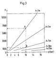
- Fig. 3
- ein Diagramm zum Bedarf an Fluidisierungsgas und
- Fig. 4
- einen bekannten Wirbelbettkühler im Längsschnitt.
- Die Vorrichtung der Fig. 1 weist eine hohe, schlanke Kühlkammer (1) auf, die einen Feststoff-Zulauf (2) und einen Feststoff-Ablauf (3) besitzt. In der Kühlkammer (1) befindet sich im Betrieb ein nicht dargestelltes Wirbelbett aus körnigen Feststoffen, die durch die Leitung (4) herangeführt werden. Das Wirbelbett reicht von einem Düsenrost (5) bis zum Ablauf (3) und es umgibt die gewendelte Leitung einer Kühleinrichtung (6), durch die man ein Kühlfluid zur Wärmeabfuhr leitet. Fluidisierungsgas wird durch die Leitung (8) herangeführt und gelangt zunächst in eine Verteilkammer (9), bevor es durch den Düsenrost (5) hindurch aufwärts steigt und das Wirbelbett fluidisiert. Nach Austritt aus dem Wirbelbett strömen die Fluidisierungsgase zunächst in einen erweiterten Beruhigungsraum (1) und verlassen die Kühlvorrichtung durch den Abzug (11), an den nicht dargestellte weitere Behandlungseinrichtungen, z.B. eine Entstaubung, angeschlossen sein können.
- Die Kühlkammer (1) kann so ausgebildet sein, daß das darin befindliche Wirbelbett eine Betthöhe von 3 bis 20 m aufweist. Die zu kühlenden körnigen Feststoffe bewegen sich vom Feststoff-Zulauf (2) unter der Wirkung des Fluidisierungsgases, z.B. Luft, in der Kühlkammer (1) aufwärts und verlassen das Wirbelbett durch den Ablauf (3). Durch diese vorgegebene Bewegung der Feststoffe kann das in der Kühleinrichtung (6) strömende Kühlfluid im Gleichstrom oder Gegenstrom zu den Feststoffen geführt werden. Zum Regeln der Menge der in das Wirbelbett eintretenden Feststoffe kann im Zulauf (2) eine Leitung (13) zum Einspeisen eines steuernden Gases vorgesehen werden. Die Kühlkammer (1) und der Beruhigungsraum (10) werden von einem druckfesten Behälter (12) eingeschlossen.
- Die Kühlvorrichtung der Fig. 2, die für das erfindungsgemäße Verfahren geeignet ist, zeigt eine erste Kühlkammer (1a) und eine zweite Kühlkammer (1b). Zwischen den Kühlkammern (1a) und (1b) befindet sich eine Trennwand (7), wobei zwischen dem Düsenrost (5) und der Unterkante der Trennwand (7) eine Öffnung (15) bleibt. Ein druckfestes Gehäuse (16) schließt die Kühlkammern ein, es weist einen Feststoff-Einlaß (22) und einen Feststoff-Ablauf (23) auf. Die Oberkante (7a) der Trennwand (7) liegt höher als der Einlaß (22) und der Ablauf (23). Wirbelgase verlassen das Gehäuse durch den Abzug (11).
- Die heißen Feststoffe, die durch den Einlaß (22) herangeführt werden, gelangen zunächst in die zweite Kühlkammer (1b), in welcher sich ein Wirbelbett befindet, das hier als "vorgeschaltetes Wirbelbett" bezeichnet wird durch die Leitung (19) herangeführt, gelangt in die Verteilkammer (20) und strömt dann aufwärts durch die zweite Kühlkammer (1b) bis zum Abzug (11). Die Feststoffe bewegen sich im vorgeschalteten Wirbelbett in der zweiten Kühlkammer (1b) abwärts und treten durch die Öffnung (15) in das Wirbelbett der ersten Kühlkammer (1a) ein. Der Bereich der Öffnung (15) besitzt eine eigene Fluidisierungsgas-Zufuhr durch die Leitung (24) und die Verteilkammer (25), die sich unter dem Düsenrost (5) befindet. Durch Verändern der durch die Leitung (24) herangeführten Gasmenge kann die Menge der durch die Öffnung (15) hindurchtretenden Feststoffe beeinflußt werden. Auf diese Weise kann man den Feststoffstrom zur ersten Kühlkammer (1a) in der Art eines fluiddynamischen Ventils steuern.
- Die Öffnung (15) dient als Feststoff-Zulauf für das Wirbelbett in der ersten Kühlkammer (1a), in welchem sich die Feststoffe im stationären Wirbelbett aufwärts bewegen, bis sie die Kühlvorrichtung durch den Ablauf (23) verlassen. Fluidisierungsgas wird durch die Leitung (26) herangeführt und tritt durch die Verteilkammer (27) und den Rost (5) in das Wirbelbett ein. Abweichend von der Darstellung der Fig. 2 können die beiden Kühlkammern (1a) und (1b) auch in einem nicht für höheren Druck ausgelegten Gehäuse angeordnet sein, das sich in einem separaten Druckgehäuse befindet, wie es in Fig. 1 dargestellt ist.
- Für die erste Kühlkammer (1a) und die zweite Kühlkammer (1b) sowie die darin befindlichen Wirbelbetten gilt das bereits zuvor für ein einzelnes Wirbelbett Gesagte bezüglich der Betthöhe, des Verhältnisses der Betthöhe zur durchschnittlichen Bettbreite und zur Temperaturdifferenz zwischen dem unteren und dem oberen Bereich eines Wirbelbettes. Wie ersichtlich, kann sowohl im vorgeschalteten Wirbelbett als auch im nachgeschalteten Wirbelbett in der ersten Kühlkammer (1a) ein Gleichstrom oder auch ein Gegenstrom zwischen Feststoffen und Kühlfluid eingestellt werden, wobei das Kühlfluid durch die Kühleinrichtung (6a) und (6b) strömt.
- In vielen Anwendungsfällen liegen die Geschwindigkeiten des Fluidisierungsgases im Bereich von 0,2 bis 0,8 m/s und sie können näherungsweise als druckunabhängig angenommen werden.
- Im Diagramm der Fig. 3 ist für eine Geschwindigkeit des Fluidisierungsgases von 0,5 m/s und einer Temperatur von 500°C sowie Korngrößen der Feststoffe im Wirbelbett von 100 bis 400 µm zum Fluidisierungsgasbedarf V (in Nm3 pro Stunde und pro m3 Wirbelbettvolumen) die ermittelte Abhängigkeit vom Druck p für verschiedene Betthöhen h (h = 1, 2, 5, 10 und 20 m) dargestellt. Hierbei zeigt z.B. Punkt (A), daß man bei p = 10 bar und einer Höhe h = 1 m mit V = 6500 arbeiten muß, wogegen man bei gleichem Druck und einer Betthöhe h = 5 m (Punkt (B)) nur ein V von etwa 1300 braucht.
- Im nachfolgend beschriebenen, teilweise berechneten Vergleich wird ein üblicher, bekannter Wirbelbettkühler von flacher Bauart gemäß Fig. 4 mit einem hohen Wirbelbettkühler gemäß Fig. 1 verglichen. Der Wirbelbettkühler der Fig. 4 hat ein Gehäuse (30) mit einem Feststoff-Zulauf (31), einem Feststoff-Ablauf (32), einem Zufuhrsystem (33) für Fluidisierungsgas und er ist durch drei wehrartige Trennwände (34) in vier Kammern (35), (36), (37) und (38) unterteilt. In jeder Kammer befindet sich ein Wirbelbett, wobei sich die Feststoffe über die Wände (34) hinweg vom Zulauf (31) durch die Wirbelbetten bis zum Ablauf (32) bewegen. Jedes Wirbelbett wird durch eine mit Kühlwasser gespeiste Kühleinrichtung (39) indirekt gekühlt, Fluidisierungsgas zieht in der Leitung (40) ab.
- Im Vergleichsbeispiel beträgt die horizontale Querschnittsfläche jeder Kammer der Einrichtung gemäß Fig. 4 0,88 m2, ebenso hat das Wirbelbett gemäß Fig. 1 eine horizontale Querschnittsfläche von 0,88 m2. Weitere Daten ergeben sich aus der nachfolgenden Tabelle:
Fig. 4 Fig. 1 Wirbelbett-Höhe 0,5 m 2,0 m Gesamtes Wirbelbett-Volumen 1,76 m3 1,76 m3 Oberfläche der Kühleinrichtung 36 m2 36 m2 Druck 10 bar 10 bar Feststoffdurchsatz 2 500 kg/h 2 500 kg/h Kühlwasserverbrauch 8 000 kg/h 8 000 kg/h Fluidisierungsgasverbrauch 48 000 kg/h 12 000 kg/h Temperaturen: Feststoffe ein 700 °C 700 °C Feststoffe aus 126 °C 123 °C Kühlwasser ein 30 °C 30 °C Kühlwasser aus 92 °C 98 °C Fluidisierungsgas ein 150 °C 150 °C Fluidisierungsgas aus 146 °C 123 °C - Für die Daten, die teilweise berechnet sind, wird von Feststoffen ausgegangen, die aus Kohlenasche bestehen und Korngrößen im Bereich von 0,1 bis 1 mm aufweisen. Als Fluidisierungsgas dient Luft, die in allen Fällen mit einer Geschwindigkeit von 0,4 bis 0,7 m/sec durch die Wirbelbetten geleitet wird.
- Die Tabelle zeigt, daß man bei gleichem Wirbelbettvolumen, gleicher Kühleinrichtung, gleichem Kühlwasserbedarf und gleicher Fluidisierungsgasgeschwindigkeit beim hohen Wirbelbett der Fig. 1 mit einem Viertel des Fluidisierungsgasbedarfs gegenüber Fig. 4 auskommt, wobei auch der konstruktive Aufwand geringer ist. Dabei wurden tote Ecken, die erfahrungsgemäß bei flachen Wirbelbettkühlern gemäß Fig. 4 bevorzugt auftreten und deren Wirksamkeit zusätzlich verschlechtern, in den Berechnungen nicht berücksichtigt.
Claims (1)
- Verfahren zum Kühlen heißer, körniger Feststoffe unter überatmosphärischem Druck bis 50 bar in einer ersten Kühlkammer (1a) und einer zweiten Kühlkammer (1b), zwischen denen sich eine Trennwand (7) befindet, die im unteren Bereich eine die beiden Kühlkammern verbindende Öffnung (15) aufweist, wobei die zu kühlenden Feststoffe in beiden Kühlkammern Wirbelbetten bilden, welche mit in beiden Kammern angeordneten Kühleinrichtungen (6a, 6b) in Kontakt stehen, wobei man die zu kühlenden Feststoffe durch einen Feststoff-Zulauf (22) oben auf das Wirbelbett der zweiten Kühlkammer (1b) leitet, die Feststoffe in der zweiten Kühlkammer vorwiegend in vertikaler Richtung nach unten zur Öffnung (15) in der Trennwand (7) führt und die Feststoffe anschließend in der ersten Kühlkammer (1a) vorwiegend in vertikaler Richtung aufwärts nach oben zu einem Feststoff-Ablauf (23) führt, und wobei man Fluidisierungsgas in den unteren Bereich der beiden Wirbelbetten einleitet und durch die von einem Kühlfluid durchströmten Kühleinrichtungen Wärme indirekt abführt, dadurch gekennzeichnet, daß die beiden Wirbelbetten eine Betthöhe von 3 bis 20 m und ein Verhältnis der Betthöhe zur durchschnittlichen Bettbreite von 3 : 1 bis 10 : 1 aufweisen, daß der Druck in beiden Wirbelbetten 5 bis 50 bar beträgt, daß sich die Kühleinrichtungen mindestens über die halbe Höhe des zugehörigen Wirbelbettes erstrecken, daß das Kühlfluid in beiden Kühleinrichtungen im Gleichstrom oder Gegenstrom zur vertikalen Bewegung der Feststoffe strömt und daß die Temperaturdifferenzen der Feststoffe zwischen dem unteren und oberen Bereich der beiden Wirbelbetten mindestens 200°C betragen.
Applications Claiming Priority (2)
| Application Number | Priority Date | Filing Date | Title |
|---|---|---|---|
| DE4213475A DE4213475A1 (de) | 1992-04-24 | 1992-04-24 | Verfahren und Vorrichtung zum Kühlen heißer Feststoffe im Wirbelbett |
| DE4213475 | 1992-04-24 |
Publications (2)
| Publication Number | Publication Date |
|---|---|
| EP0567167A1 EP0567167A1 (de) | 1993-10-27 |
| EP0567167B1 true EP0567167B1 (de) | 1996-10-09 |
Family
ID=6457374
Family Applications (1)
| Application Number | Title | Priority Date | Filing Date |
|---|---|---|---|
| EP93200703A Expired - Lifetime EP0567167B1 (de) | 1992-04-24 | 1993-03-11 | Verfahren zum Kühlen heisser Feststoffe im Wirbelbett |
Country Status (9)
| Country | Link |
|---|---|
| EP (1) | EP0567167B1 (de) |
| JP (1) | JP3358632B2 (de) |
| CA (1) | CA2091654A1 (de) |
| CZ (1) | CZ288550B6 (de) |
| DE (2) | DE4213475A1 (de) |
| ES (1) | ES2092744T3 (de) |
| FI (1) | FI107641B (de) |
| HU (1) | HUT65400A (de) |
| SK (1) | SK282384B6 (de) |
Cited By (1)
| Publication number | Priority date | Publication date | Assignee | Title |
|---|---|---|---|---|
| CN103153450A (zh) * | 2010-08-09 | 2013-06-12 | 南方公司 | 高温和高压环境中冷却灰粉和固体颗粒 |
Families Citing this family (5)
| Publication number | Priority date | Publication date | Assignee | Title |
|---|---|---|---|---|
| FR2723186B1 (fr) * | 1994-07-28 | 1996-09-13 | Gec Alsthom Stein Ind | Dispositif de refroidissement de particules solides en sortie d'un agencement de traitement |
| JP3595435B2 (ja) * | 1997-08-04 | 2004-12-02 | 三菱重工業株式会社 | 粒子移動量制御装置 |
| US6138377A (en) * | 1999-07-21 | 2000-10-31 | United States Gypsum Company | Apparatus and process for cooling and de-steaming calcined stucco |
| DE10153452B4 (de) * | 2001-11-04 | 2006-11-30 | Fritz Curtius | Wärmetauscher für Kühlanlagen |
| WO2024064648A1 (en) * | 2022-09-19 | 2024-03-28 | Flying Diamonds Energy Company, Llc | Thermal storage unit |
Family Cites Families (2)
| Publication number | Priority date | Publication date | Assignee | Title |
|---|---|---|---|---|
| GB8810390D0 (en) * | 1988-05-03 | 1988-06-08 | Shell Int Research | Apparatus & process for exchanging heat between solid particles & heat exchange medium |
| FR2667061B1 (fr) * | 1990-09-25 | 1993-07-16 | Inst Francais Du Petrole | Procede de conversion en lit fluide d'une charge contenant une majeure partie d'au moins un compose oxygene. |
-
1992
- 1992-04-24 DE DE4213475A patent/DE4213475A1/de not_active Withdrawn
-
1993
- 1993-03-11 EP EP93200703A patent/EP0567167B1/de not_active Expired - Lifetime
- 1993-03-11 ES ES93200703T patent/ES2092744T3/es not_active Expired - Lifetime
- 1993-03-11 DE DE59304075T patent/DE59304075D1/de not_active Expired - Fee Related
- 1993-03-15 CA CA002091654A patent/CA2091654A1/en not_active Abandoned
- 1993-04-16 CZ CZ1993659A patent/CZ288550B6/cs not_active IP Right Cessation
- 1993-04-19 SK SK360-93A patent/SK282384B6/sk not_active IP Right Cessation
- 1993-04-23 JP JP12088693A patent/JP3358632B2/ja not_active Expired - Fee Related
- 1993-04-23 HU HU9301202A patent/HUT65400A/hu unknown
- 1993-04-23 FI FI931845A patent/FI107641B/fi active
Cited By (2)
| Publication number | Priority date | Publication date | Assignee | Title |
|---|---|---|---|---|
| CN103153450A (zh) * | 2010-08-09 | 2013-06-12 | 南方公司 | 高温和高压环境中冷却灰粉和固体颗粒 |
| CN103153450B (zh) * | 2010-08-09 | 2015-01-28 | 南方公司 | 高温和高压环境中冷却灰粉和固体颗粒 |
Also Published As
| Publication number | Publication date |
|---|---|
| JPH0626613A (ja) | 1994-02-04 |
| CZ65993A3 (en) | 1993-11-17 |
| HUT65400A (en) | 1994-06-28 |
| DE59304075D1 (de) | 1996-11-14 |
| SK282384B6 (sk) | 2002-01-07 |
| SK36093A3 (en) | 1993-11-10 |
| FI931845L (fi) | 1993-10-25 |
| FI931845A0 (fi) | 1993-04-23 |
| ES2092744T3 (es) | 1996-12-01 |
| CA2091654A1 (en) | 1993-10-25 |
| CZ288550B6 (cs) | 2001-07-11 |
| HU9301202D0 (en) | 1993-08-30 |
| EP0567167A1 (de) | 1993-10-27 |
| DE4213475A1 (de) | 1993-10-28 |
| FI107641B (fi) | 2001-09-14 |
| JP3358632B2 (ja) | 2002-12-24 |
Similar Documents
| Publication | Publication Date | Title |
|---|---|---|
| EP0087039B1 (de) | Verfahren zum gleichzeitigen Sichten und geregelten, kontinuierlichen Austrag von körnigem Gut aus Wirbelbettreaktoren | |
| DE69512196T2 (de) | Verfahren und Einrichtung zur Strippung von suspendierten Feststoffen und Anwendung in Fliesskrackverfahren | |
| DE19514187C1 (de) | Verfahren und Vorrichtung zur Herstellung von Granulaten durch Wirbelschicht-Sprühgranulation | |
| DE69101920T2 (de) | Verfahren und vorrichtung zum kristallisieren eines minerals. | |
| DE4118433C2 (de) | Fließbettapparatur zum Behandeln partikelförmigen Gutes | |
| CH668196A5 (de) | Verfahren und einrichtung zum abkuehlen und entstauben von gasen. | |
| DE10144747A1 (de) | Kontinuierliche thermische Behandlung von Schüttgütern | |
| DE10322062A1 (de) | Verfahren und Vorrichtung zum Aufbringen von Flüssigkeiten in eine Feststoffströmung eines Strahlschichtapparates | |
| DE2654107C2 (de) | Wirbelschichtvorrichtung | |
| EP0550923B1 (de) | Verfahren und Vorrichtung zum Kühlen der heissen Feststoffe eines Wirbelschichtreaktors | |
| EP0810902A1 (de) | Vorrichtung und ihre verwendung zur oxichlorierung | |
| EP0567167B1 (de) | Verfahren zum Kühlen heisser Feststoffe im Wirbelbett | |
| DE2307165A1 (de) | Verfahren und vorrichtung zur direkten kuehlung von feinkoernigem bis grobkoernigem gut mittels kuehlluft | |
| EP1279433B1 (de) | Verfahren zum Coating von Babynahrung | |
| DE4142814A1 (de) | Auf umlaufmassentechnik basierendes verfahren zum abkuehlen von gasen und beim verfahren verwendbarer umlaufmassenkuehler | |
| DE3013645A1 (de) | Verfahren und vorrichtung fuer die zufuehrung von teilchen in eine wirbelschicht | |
| DE602004002960T2 (de) | Vorrichtung und verfahren zur wirbelschichtgranulation | |
| DE19700029B4 (de) | Wirbelschichtapparat | |
| DE2839821A1 (de) | Wirbelschichtverfahren und reaktor | |
| DD210215A5 (de) | Verfahren und vorrichtung zur abscheidung von materialien aus gasen oder fluessigkeiten | |
| DE3501371A1 (de) | Verfahren und vorrichtung zur fraktionierten desublimation von dampffoermigen feststoffen aus gas-dampf-gemischen | |
| EP1035048B1 (de) | Vorrichtung zur Aufteilung eines Zustroms von Feststoffpartikeln in Teilströme | |
| DE2608712B1 (de) | Vorrichtung zur behandlung von koernigen festgut mit fliessfaehigen medien | |
| EP0543429A1 (de) | Wirbelbettkühler für eine Anlage zum thermischen Behandeln körniger Feststoffe in der Wirbelschicht | |
| EP0097332B1 (de) | Wirbelschicht-Wärmeaustauscher |
Legal Events
| Date | Code | Title | Description |
|---|---|---|---|
| PUAI | Public reference made under article 153(3) epc to a published international application that has entered the european phase |
Free format text: ORIGINAL CODE: 0009012 |
|
| AK | Designated contracting states |
Kind code of ref document: A1 Designated state(s): DE ES FR GB IT SE |
|
| 17P | Request for examination filed |
Effective date: 19940305 |
|
| 17Q | First examination report despatched |
Effective date: 19950726 |
|
| GRAG | Despatch of communication of intention to grant |
Free format text: ORIGINAL CODE: EPIDOS AGRA |
|
| GRAH | Despatch of communication of intention to grant a patent |
Free format text: ORIGINAL CODE: EPIDOS IGRA |
|
| GRAH | Despatch of communication of intention to grant a patent |
Free format text: ORIGINAL CODE: EPIDOS IGRA |
|
| RBV | Designated contracting states (corrected) |
Designated state(s): DE ES FR GB SE |
|
| GRAA | (expected) grant |
Free format text: ORIGINAL CODE: 0009210 |
|
| AK | Designated contracting states |
Kind code of ref document: B1 Designated state(s): DE ES FR GB SE |
|
| REF | Corresponds to: |
Ref document number: 59304075 Country of ref document: DE Date of ref document: 19961114 |
|
| ET | Fr: translation filed | ||
| REG | Reference to a national code |
Ref country code: ES Ref legal event code: FG2A Ref document number: 2092744 Country of ref document: ES Kind code of ref document: T3 |
|
| GBT | Gb: translation of ep patent filed (gb section 77(6)(a)/1977) |
Effective date: 19961202 |
|
| PLBE | No opposition filed within time limit |
Free format text: ORIGINAL CODE: 0009261 |
|
| STAA | Information on the status of an ep patent application or granted ep patent |
Free format text: STATUS: NO OPPOSITION FILED WITHIN TIME LIMIT |
|
| 26N | No opposition filed | ||
| REG | Reference to a national code |
Ref country code: GB Ref legal event code: IF02 |
|
| REG | Reference to a national code |
Ref country code: GB Ref legal event code: 732E |
|
| REG | Reference to a national code |
Ref country code: FR Ref legal event code: CD |
|
| REG | Reference to a national code |
Ref country code: FR Ref legal event code: TP Ref country code: FR Ref legal event code: CD |
|
| PGFP | Annual fee paid to national office [announced via postgrant information from national office to epo] |
Ref country code: ES Payment date: 20080328 Year of fee payment: 16 |
|
| PGFP | Annual fee paid to national office [announced via postgrant information from national office to epo] |
Ref country code: SE Payment date: 20080313 Year of fee payment: 16 Ref country code: GB Payment date: 20080320 Year of fee payment: 16 |
|
| PGFP | Annual fee paid to national office [announced via postgrant information from national office to epo] |
Ref country code: FR Payment date: 20080314 Year of fee payment: 16 Ref country code: DE Payment date: 20080321 Year of fee payment: 16 |
|
| EUG | Se: european patent has lapsed | ||
| GBPC | Gb: european patent ceased through non-payment of renewal fee |
Effective date: 20090311 |
|
| REG | Reference to a national code |
Ref country code: FR Ref legal event code: ST Effective date: 20091130 |
|
| PG25 | Lapsed in a contracting state [announced via postgrant information from national office to epo] |
Ref country code: DE Free format text: LAPSE BECAUSE OF NON-PAYMENT OF DUE FEES Effective date: 20091001 |
|
| PG25 | Lapsed in a contracting state [announced via postgrant information from national office to epo] |
Ref country code: GB Free format text: LAPSE BECAUSE OF NON-PAYMENT OF DUE FEES Effective date: 20090311 Ref country code: FR Free format text: LAPSE BECAUSE OF NON-PAYMENT OF DUE FEES Effective date: 20091123 |
|
| REG | Reference to a national code |
Ref country code: ES Ref legal event code: FD2A Effective date: 20090312 |
|
| PG25 | Lapsed in a contracting state [announced via postgrant information from national office to epo] |
Ref country code: ES Free format text: LAPSE BECAUSE OF NON-PAYMENT OF DUE FEES Effective date: 20090312 |
|
| PG25 | Lapsed in a contracting state [announced via postgrant information from national office to epo] |
Ref country code: SE Free format text: LAPSE BECAUSE OF NON-PAYMENT OF DUE FEES Effective date: 20090312 |