EP0567122A1 - Electric suspended railway - Google Patents
Electric suspended railway Download PDFInfo
- Publication number
- EP0567122A1 EP0567122A1 EP93106558A EP93106558A EP0567122A1 EP 0567122 A1 EP0567122 A1 EP 0567122A1 EP 93106558 A EP93106558 A EP 93106558A EP 93106558 A EP93106558 A EP 93106558A EP 0567122 A1 EP0567122 A1 EP 0567122A1
- Authority
- EP
- European Patent Office
- Prior art keywords
- running rail
- station
- drive wheel
- electric
- track section
- Prior art date
- Legal status (The legal status is an assumption and is not a legal conclusion. Google has not performed a legal analysis and makes no representation as to the accuracy of the status listed.)
- Granted
Links
- 230000000903 blocking effect Effects 0.000 claims description 2
- 230000006835 compression Effects 0.000 description 9
- 238000007906 compression Methods 0.000 description 9
- 238000006073 displacement reaction Methods 0.000 description 7
- 238000013016 damping Methods 0.000 description 4
- 239000006096 absorbing agent Substances 0.000 description 1
- 230000000295 complement effect Effects 0.000 description 1
- 230000035939 shock Effects 0.000 description 1
- 230000007704 transition Effects 0.000 description 1
Images

Classifications
-
- B—PERFORMING OPERATIONS; TRANSPORTING
- B61—RAILWAYS
- B61C—LOCOMOTIVES; MOTOR RAILCARS
- B61C13/00—Locomotives or motor railcars characterised by their application to special systems or purposes
- B61C13/04—Locomotives or motor railcars characterised by their application to special systems or purposes for elevated railways with rigid rails
-
- B—PERFORMING OPERATIONS; TRANSPORTING
- B61—RAILWAYS
- B61B—RAILWAY SYSTEMS; EQUIPMENT THEREFOR NOT OTHERWISE PROVIDED FOR
- B61B3/00—Elevated railway systems with suspended vehicles
- B61B3/02—Elevated railway systems with suspended vehicles with self-propelled vehicles
Definitions
- the invention relates to an electric monorail conveyor according to the preamble of the main claim.
- Such an electric monorail conveyor is known from European Patent 0 144 886.
- an electric vehicle In the known electric monorail system, an electric vehicle is brought to a standstill when it enters a station by braking and blocking the drive wheel. Depending on its inertial mass, it comes to a standstill more or less far before the desired position. It must then be pushed into the desired end position by a positioning device. However, this shift is countered by the friction of the blocked drive wheel on the running rail, depending on the load, with a greater or lesser resistance.
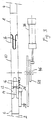
- Figure 1 shows a generally designated 1 displacement unit between two rails 2,4 in a station.
- the displacement unit 1 comprises two stationary running rail sections 6, 8 and a displaceable running rail section 10.
- the end regions of the two stationary running sections 6, 8 facing the displaceable running rail section 10 each have two upper recesses 12 between which a web 14 is provided.
- the displaceable running rail section 10 is designed at both ends to be complementary to the end regions of the stationary running rail sections 6, 8. It carries two longitudinal tines 16, which correspond to the recesses 12 and protrude into them.
- the displaceable running rail section 10 is shorter by a certain amount b than the clear width between the ends of the stationary running rail sections 6, 8.
- the track section 10 is displaceable in the longitudinal direction by this amount b.
- Fig.1 it is shown in its right end position.
- the length of the tines 16 is selected so that they completely fill the recesses 12 on the side of an end position, but still protrude a short distance into the recesses 12 on the other side.
- This intermeshed structure ensures that the sliding track section 10 on both sides rests and there is a smooth transition to the stationary track sections 6, 8.
- the surfaces of the track sections 6,8,10 are aligned.
- the two running rail sections 6, 8 are integrally connected to one another in the lower region, which is designed as an inverted T-profile.
- This structure can be obtained by providing an upper recess for accommodating the movable track section 10 from an ordinary track section.
- a lower one-piece connecting piece 18 remains between the intact, stationary running rail sections 6, 8.
- the displaceable running rail section 10 has a lower web 22 on which two rollers 24 are mounted. These roll on the auxiliary rail 20.
- a compression spring 26 normally presses the displaceable running rail section 10 into its right end position.
- the compression spring 26 is supported on a damping cylinder 28.
- the rod 30 of the damping cylinder extends through the compression spring 26.
- a positioning device serves to move the displaceable running rail section 10 from the end position shown in FIG. 1 to the left against the force of the spring 26.
- This positioning device is in detail in European Patent 0 144 886, which is expressly incorporated by reference for disclosure purposes. It comprises an actuating cylinder 36 for a carriage 38 to which a driver pawl 40 is articulated.
- a stop member 42 defines the desired position of the electric vehicle. The latter is represented by a drive wheel 44 and a locking pin 46.
- the mode of operation of the displacement unit will be explained below.
- the starting position is shown in Fig.1.
- An electric vehicle drives into the station by driving the drive wheel 44.
- the electric vehicle is switched off, braked and the drive wheel 44 blocked. It is made of plastic with high adhesion.
- the exact position ie the caster, depends on the inertial mass.
- the spring force of the compression spring 26 is sufficient to hold the movable track section in the starting position.
- the locking pin 46 acts on the driver pawl 40, which is pivoted clockwise and thus does not hinder the journey.
- the driver pawl then turns back into the position shown in FIG. 1. Now the actuating cylinder 36 is acted upon.
- the carriage 38 is moved to the left and the driver pawl 40 engages the locking pin 46.
- the electric vehicle is moved to the left until it engages the stop member 42.
- the movable track section 10 is entrained by the drive wheel 44 by frictional force.
- the distance by which the electric vehicle is shifted between the braking position (shown in FIG. 1) and the end position (defined by 42) is smaller than the free path b by which the movable track section 10 can be moved.
- the damping cylinder 28 dampens the movement before reaching the end position.
- the stop member 42 Before the electric vehicle can continue, the stop member 42 must be released. Now the electric vehicle driven by its own motor power can drive over the stop member 42, which is pivoted clockwise by the locking bolt 46. It then returns to the swivel position shown in FIG. 1. Now the drive wheel 44 leaves the movable track section 10 and this returns under the action of the compression spring 26 to the normal end position.
- the shock absorber 28 can be omitted.
- a tension spring can be provided instead of the compression spring 26.
- a combination of a compression spring and a tension spring can also be provided.
- Fener can provide the movable track section 10 with an axial brake or a magnetic brake be. This is switched on after the electric vehicle has reached the end position and holds the movable track section 10 in the left position. Only after the axial brake has been released can the compression spring 26 push the movable track section back into the starting position.
Landscapes
- Engineering & Computer Science (AREA)
- Transportation (AREA)
- Mechanical Engineering (AREA)
- Electric Propulsion And Braking For Vehicles (AREA)
- Platform Screen Doors And Railroad Systems (AREA)
- Current-Collector Devices For Electrically Propelled Vehicles (AREA)
- Carriers, Traveling Bodies, And Overhead Traveling Cranes (AREA)
- Screw Conveyors (AREA)
- Harvesting Machines For Root Crops (AREA)
- Insulated Conductors (AREA)
- Lubricants (AREA)
- Electrochromic Elements, Electrophoresis, Or Variable Reflection Or Absorption Elements (AREA)
- Drying Of Solid Materials (AREA)
Abstract
Description
Die Erfindung betrifft eine Elektrohängebahn gemäß dem Oberbegriff des Hauptanspruchs. Eine solche Elektrohängebahn ist bekannt aus dem Europäischen Patent 0 144 886.The invention relates to an electric monorail conveyor according to the preamble of the main claim. Such an electric monorail conveyor is known from European Patent 0 144 886.
Bei der bekannten Elektrohängebahn wird ein Elektrofahrzeug beim Einfahren in eine Station durch Abbremsen und Blockieren des Antriebrades stillgesetzt. Dabei kommt es abhängig von seiner trägen Masse mehr oder weniger weit vor der gewünschten Position zum Stillstand. Es muß anschließend durch eine Positioniereinrichtung in die gewünschte Endposition geschoben werden. Dieser Verschiebung setzt jedoch die Reibung des blockierten Antriebrades auf der Laufschiene je nach Last einen mehr oder weniger großen Widerstand entgegen.In the known electric monorail system, an electric vehicle is brought to a standstill when it enters a station by braking and blocking the drive wheel. Depending on its inertial mass, it comes to a standstill more or less far before the desired position. It must then be pushed into the desired end position by a positioning device. However, this shift is countered by the friction of the blocked drive wheel on the running rail, depending on the load, with a greater or lesser resistance.
Es ist somit Aufgabe der Erfindung die bekannte Elektrohängebahn derart weiterzubilden, daß das Positionieren eines Elektrohängefahrzeugs bei blockiertem Antriebsrad erleichert wird. Diese Aufgabe wird durch die Elektrohängebahn gemäß Hauptanspruch gelöst.It is therefore an object of the invention to develop the known electric monorail system in such a way that the positioning of an electric monorail vehicle is facilitated when the drive wheel is blocked. This task is solved by the electric monorail system according to the main claim.
Im folgenden wird die Erfindung anhand von Zeichnungen näher erläutert. Es zeigen
- Fig.1 eine Seitenansicht einer Verschiebeeinheit einer Elektrohängebahn gemäß der Erfindung;
- Fig.2 einen Schnitt entlang der Linie A-A der
Figur 1; und - Fig.3 eine Draufsicht der Verschiebeeinheit gemäß Fig.1.
- 1 shows a side view of a displacement unit of an electric monorail conveyor according to the invention;
- 2 shows a section along the line AA of Figure 1; and
- 3 shows a top view of the displacement unit according to FIG. 1.
Figur 1 zeigt eine allgemein mit 1 bezeichnete Verschiebeeinheit zwischen zwei Laufschienen 2,4 in einer Station. Die Verschiebeeinheit 1 umfasst zwei stationäre Laufschienenabschnitte 6,8 und einen verschiebbaren Laufschienenabschnitt 10. Die dem verschiebbaren Laufschienenabschnitt 10 zugewandten Endbereiche der beiden stationären Laufabschnitte 6,8 weisen je zwei obere Ausnehmungen 12 auf zwischen denen je ein Steg 14 vorgesehen ist. Der verschiebbare Laufschienenabschnitt 10 ist an seinen beiden Enden komplementär zu den Endbereichen der stationären Laufschienenabschnitte 6,8 ausgebildet. Er trägt je zwei Längszinken 16, welche den Ausnehmungen 12 entsprechen und in diese hineinragen. Der verschiebbare Laufschienenabschnitt 10 ist um einen bestimmten Betrag b kürzer als die lichte Weite zwischen den Enden der stationären Laufschienenabschnitte 6,8. Um diesen Betrag b ist der Laufschienenabschnitt 10 in Längsrichtung verschiebbar. In Fig.1 ist er in seiner rechten Endlage gezeigt. Die Länge der Zinken 16 ist so gewählt, daß sie auf der Seite einer Endlage die Ausnehmungen 12 vollständig ausfüllen, auf der anderen Seite aber immer noch ein kurzes Stück in die Ausnehmungen 12 hineinragen. Durch diese verkämmte Struktur wird gewährleistet, daß der verschiebbare Laufschienenabschnitt 10 beidseitig aufliegt und ein glatter Übergang zu den stationären Laufschienenabschnitten 6,8 besteht. Die Oberflächen der Laufschienenabschnitte 6,8,10 fluchten.Figure 1 shows a generally designated 1 displacement unit between two
Die beiden Laufschienenabschnitte 6,8 sind im unteren, als umgekehrtes T-Profil ausgebildeten Bereich einstückig miteinander verbunden. Diese Struktur kann dadurch erhalten werden, daß man aus einem gewöhnlichen Laufschienenabschnitt eine obere Ausnehmung für die Unterbringung des beweglichen Laufschienenabschnitts 10 vorsieht. Dabei verbleibt zwischen den intakten, stationären Laufschienenabschnitten 6,8 ein unteres einstückiges Verbindungstück 18. Auf dessen oberen Rand ist eine Hilfsschiene 20 befestigt. Andererseits weist der verschiebbare Laufschienenabschnitt 10 einen unteren Steg 22 auf an dem zwei Rollen 24 gelagert sind. Diese rollen auf der Hilfsschiene 20. Eine Druckfeder 26 drückt den verschiebbaren Laufschienenabschnitt 10 normalerweise in seine rechte Endlage. Die Druckfeder 26 stützt sich an einem Dämpfungszylinder 28 ab. Die Stange 30 des Dämpfungszylinders erstreckt sich durch die Druckfeder 26. Sie hat an ihrem, dem Dämpfungszylinder 28 abgewandten Ende einen erweiterten Kopf 32, der durch die Druckfeder 26 gegen den Steg 22 des verschiebbaren Laufschienenabschnitts gedrückt wird. Eine allgemein mit 34 bezeichnete Positioniereinrichtung dient der Verschiebung des verschiebbaren Laufschienenabschnitts 10 aus der in Fig.1 gezeigten Endlage nach links gegen die Kraft der Feder 26. Diese Positioniereinrichtung ist im einzelnen in dem europäischen Patent 0 144 886 beschrieben, auf das zu Offenbarungszwecken ausdrücklich Bezug genommen wird. Sie umfasst einen Betätigungszylinder 36 für einen Schlitten 38, an dem eine Mitnehmerklinke 40 angelenkt ist. Ein Anschlagglied 42 definiert die gewünschte Position des Elektrofahrzeugs. Letzteres ist durch ein Antriebsrad 44 und einen Sperrbolzen 46 repräsentiert.The two
Im folgenden soll die Arbeitsweise der Verschiebeeinheit erläutert werden. Die Ausgangsposition ist in Fig.1 gezeigt. Ein Elektrofahrzeug fährt durch Motorantrieb des Antriebrades 44 in die Station ein. Vor Erreichen der gewünschten Endposition wird das Elektrofahrzeug ausgeschaltet, abgebremst und das Antriebsrad 44 blockiert. Es besteht aus Kunststoff mit einer hohen Haftung. Dadurch kommt das Elektrofahrzeug auf dem bewegbaren Laufschienenabschnitt 10 zum Stehen. Die genaue Position, d.h. der Nachlauf hängt von der trägen Masse ab. Die Federkraft der Druckfeder 26 reicht aus dabei den bewegbaren Laufschienenabschnitt in der Ausgangsposition zu halten. Der Sperrbolzen 46 wirkt bei dieser Bewegung des Elektrofahrzeugs auf die Mitnehmerklinke 40 ein, welche im Uhrzeigersinn verschwenkt wird und somit die Fahrt nicht behindert. Anschließend dreht sich die Mitnehmerklinke wieder in die in Fig.1 gezeigte Position zurück. Nun wird der Betätigungszylinder 36 beaufschlagt. Der Schlitten 38 wird nach links bewegt und die Mitnehmerklinke 40 greift an dem Sperrbolzen 46 an.The mode of operation of the displacement unit will be explained below. The starting position is shown in Fig.1. An electric vehicle drives into the station by driving the
Hierdurch wird das Elektrofahrzeug nach links bewegt, bis es am Anschlagsglied 42 angreift. Bei dieser Verschiebebewegung wird der bewegbare Laufschienenabschnitt 10 durch Reibungskraft durch das Antriebsrad 44 mitgenommen. Die Strecke um die das Elektrofahrzeug zwischen Bremsposition (in Fig.1 gezeigt) und der Endposition (durch 42 definiert) verschoben wird ist kleiner als die freie Wegstrecke b um die der bewegbare Laufschienenabschnitt 10 bewegbar ist. Der Dämpfungszylinder 28 dämpft die Bewegung vor Erreichen der Endposition ab.As a result, the electric vehicle is moved to the left until it engages the
Bevor das Elektrofahrzeug weiterfahren kann, muß das Anschlagsglied 42 freigegeben werden. Nun kann das mit eigener Motorkraft angetriebene Elektrofahrzeug das Anschlagsglied 42 überfahren, welches dabei durch den Sperrbolzen 46 im Uhrzeigersinn verschwenkt wird. Nachfolgend kehrt es wieder in die in Fig.1 gezeigte Schwenkposition zurück. Nun verläßt das Antriebsrad 44 den bewegbaren Laufschienenabschnitt 10 und dieser kehrt unter Einwirkung der Druckfeder 26 in die normale Endlage zurück.Before the electric vehicle can continue, the
Dieser Grundaufbau der Verschiebeeinheit kann in mannigfacher Weise abgewandelt werden. Der Stoßdämpfer 28 kann entfallen. An Stelle der Druckfeder 26 kann eine Zugfeder vorgesehen sein. Es kann auch eine Kombination einer Druckfeder und einer Zugfeder vorgesehen sein. Fener kann der bewegbare Laufschienenabschnitt 10 mit einer Axialbremse oder einer Magnetbremse versehen sein. Diese wird eingeschaltet, nachdem das Elektrofahrzeug die Endposition erreicht hat und hält den bewegbaren Laufschienenabschnitt 10 in der linken Position. Erst nach Freigabe der Axialbremse vermag die Druckfeder 26 den bewegbaren Laufschienenabschnitt in die Ausgangsposition zurückzuschieben.This basic structure of the displacement unit can be modified in a variety of ways. The
Claims (6)
Applications Claiming Priority (2)
| Application Number | Priority Date | Filing Date | Title |
|---|---|---|---|
| DE4213392 | 1992-04-23 | ||
| DE4213392A DE4213392C2 (en) | 1992-04-23 | 1992-04-23 | Monorail conveyor |
Publications (2)
| Publication Number | Publication Date |
|---|---|
| EP0567122A1 true EP0567122A1 (en) | 1993-10-27 |
| EP0567122B1 EP0567122B1 (en) | 1996-07-03 |
Family
ID=6457334
Family Applications (1)
| Application Number | Title | Priority Date | Filing Date |
|---|---|---|---|
| EP93106558A Expired - Lifetime EP0567122B1 (en) | 1992-04-23 | 1993-04-22 | Electric suspended railway |
Country Status (5)
| Country | Link |
|---|---|
| EP (1) | EP0567122B1 (en) |
| AT (1) | ATE139960T1 (en) |
| DE (2) | DE4213392C2 (en) |
| DK (1) | DK0567122T3 (en) |
| ES (1) | ES2058044T3 (en) |
Cited By (1)
| Publication number | Priority date | Publication date | Assignee | Title |
|---|---|---|---|---|
| EP2289756A1 (en) | 2009-08-26 | 2011-03-02 | ROFA Rosenheimer Förderanlagen GmbH | Electrical rail transportation system |
Citations (3)
| Publication number | Priority date | Publication date | Assignee | Title |
|---|---|---|---|---|
| US3085659A (en) * | 1961-03-21 | 1963-04-16 | Richards Wilcox Mfg Co | Cushioned retarder |
| FR2181232A5 (en) * | 1972-04-20 | 1973-11-30 | Merlin Gerin | |
| DE4006746A1 (en) * | 1989-03-08 | 1990-09-13 | Volkswagen Ag | Control system for electrically-driven overhead conveyor - has magnetic switch which is actuated by swinging arm, then held retracted by pawl |
Family Cites Families (1)
| Publication number | Priority date | Publication date | Assignee | Title |
|---|---|---|---|---|
| DE3345039C2 (en) * | 1983-12-13 | 1994-12-01 | Rosenheimer Foerderanlage | Positioning device for a trolley of an electric monorail |
-
1992
- 1992-04-23 DE DE4213392A patent/DE4213392C2/en not_active Expired - Fee Related
-
1993
- 1993-04-22 ES ES93106558T patent/ES2058044T3/en not_active Expired - Lifetime
- 1993-04-22 DK DK93106558.5T patent/DK0567122T3/en active
- 1993-04-22 DE DE59303107T patent/DE59303107D1/en not_active Expired - Fee Related
- 1993-04-22 EP EP93106558A patent/EP0567122B1/en not_active Expired - Lifetime
- 1993-04-22 AT AT93106558T patent/ATE139960T1/en not_active IP Right Cessation
Patent Citations (3)
| Publication number | Priority date | Publication date | Assignee | Title |
|---|---|---|---|---|
| US3085659A (en) * | 1961-03-21 | 1963-04-16 | Richards Wilcox Mfg Co | Cushioned retarder |
| FR2181232A5 (en) * | 1972-04-20 | 1973-11-30 | Merlin Gerin | |
| DE4006746A1 (en) * | 1989-03-08 | 1990-09-13 | Volkswagen Ag | Control system for electrically-driven overhead conveyor - has magnetic switch which is actuated by swinging arm, then held retracted by pawl |
Cited By (1)
| Publication number | Priority date | Publication date | Assignee | Title |
|---|---|---|---|---|
| EP2289756A1 (en) | 2009-08-26 | 2011-03-02 | ROFA Rosenheimer Förderanlagen GmbH | Electrical rail transportation system |
Also Published As
| Publication number | Publication date |
|---|---|
| DE4213392A1 (en) | 1993-10-28 |
| ES2058044T1 (en) | 1994-11-01 |
| EP0567122B1 (en) | 1996-07-03 |
| DK0567122T3 (en) | 1996-08-05 |
| ES2058044T3 (en) | 1996-11-01 |
| DE59303107D1 (en) | 1996-08-08 |
| ATE139960T1 (en) | 1996-07-15 |
| DE4213392C2 (en) | 1995-12-07 |
Similar Documents
| Publication | Publication Date | Title |
|---|---|---|
| DE3241924C2 (en) | Device for guiding flexible supply lines | |
| EP0602390A1 (en) | Cross-bar for the roof-rack of a vehicle provided with slats | |
| EP0936119A1 (en) | Pivotable sliding door for vehicles | |
| DE2420742B2 (en) | SWEEPER FOR HIGH SPEED | |
| DE2730959C3 (en) | Application device for friction brakes, in particular for rail vehicles | |
| EP0567122B1 (en) | Electric suspended railway | |
| EP0169349B1 (en) | Fixing device for moving stairs steps | |
| DE2914448A1 (en) | DEVICE FOR SLIDING THE FILTER PLATES OF A FILTER PRESS | |
| DE2450802A1 (en) | Railway switch points clamp tip locking mechanism - with inner and outer blocking cams to engage clamp head block faces | |
| DE69507133T2 (en) | DEVICE FOR HANGING CONVEYORS | |
| DE4213288C2 (en) | Hydraulic push and pull device, in particular for railroad tracks | |
| DE2359002C3 (en) | Hydraulic braking device for an electromagnetically supported and guided vehicle with linear motor drive | |
| DE7739969U1 (en) | Leaf spring | |
| EP0737791A1 (en) | Rail system for mobile partition wall elements | |
| DE2460956C3 (en) | The centerpiece for switches and crossings | |
| EP0267413B1 (en) | Inclined lift, in particular for goods or persons | |
| DE392415C (en) | Rail brake | |
| DE2340779C3 (en) | Hydraulic braking device for rail vehicles | |
| DE19817933A1 (en) | Winch rope guide for aligning rope lines | |
| DE3122572C2 (en) | Brake trolley for a positively driven railroad | |
| DE2759577C2 (en) | Method and device for magnetically holding a vehicle in relation to a driveway | |
| DE3101944A1 (en) | Sliding roof for buildings | |
| DE2431867C2 (en) | Switch for two-lane overhead monorail vehicles | |
| EP0020861A1 (en) | Coupling device for endless conveyors | |
| DE2652799A1 (en) | HANGER OF THE DOUBLE RAIL CONSTRUCTION |
Legal Events
| Date | Code | Title | Description |
|---|---|---|---|
| PUAI | Public reference made under article 153(3) epc to a published international application that has entered the european phase |
Free format text: ORIGINAL CODE: 0009012 |
|
| AK | Designated contracting states |
Kind code of ref document: A1 Designated state(s): AT BE CH DE DK ES FR GB GR IE IT LI LU MC NL PT SE |
|
| 17P | Request for examination filed |
Effective date: 19940301 |
|
| REG | Reference to a national code |
Ref country code: ES Ref legal event code: BA2A Ref document number: 2058044 Country of ref document: ES Kind code of ref document: T3 |
|
| 17Q | First examination report despatched |
Effective date: 19950530 |
|
| GRAH | Despatch of communication of intention to grant a patent |
Free format text: ORIGINAL CODE: EPIDOS IGRA |
|
| RAP1 | Party data changed (applicant data changed or rights of an application transferred) |
Owner name: UTTSCHEID, GEORG |
|
| RIN1 | Information on inventor provided before grant (corrected) |
Inventor name: UTTSCHEID, GEORG |
|
| GRAA | (expected) grant |
Free format text: ORIGINAL CODE: 0009210 |
|
| AK | Designated contracting states |
Kind code of ref document: B1 Designated state(s): AT BE CH DE DK ES FR GB GR IE IT LI LU MC NL PT SE |
|
| PG25 | Lapsed in a contracting state [announced via postgrant information from national office to epo] |
Ref country code: GR Free format text: LAPSE BECAUSE OF FAILURE TO SUBMIT A TRANSLATION OF THE DESCRIPTION OR TO PAY THE FEE WITHIN THE PRESCRIBED TIME-LIMIT Effective date: 19960703 |
|
| REF | Corresponds to: |
Ref document number: 139960 Country of ref document: AT Date of ref document: 19960715 Kind code of ref document: T |
|
| ITF | It: translation for a ep patent filed | ||
| REG | Reference to a national code |
Ref country code: CH Ref legal event code: NV Representative=s name: A. BRAUN, BRAUN, HERITIER, ESCHMANN AG PATENTANWAE |
|
| REG | Reference to a national code |
Ref country code: DK Ref legal event code: T3 |
|
| REG | Reference to a national code |
Ref country code: IE Ref legal event code: FG4D Free format text: 68976 |
|
| REF | Corresponds to: |
Ref document number: 59303107 Country of ref document: DE Date of ref document: 19960808 |
|
| ET | Fr: translation filed | ||
| GBT | Gb: translation of ep patent filed (gb section 77(6)(a)/1977) |
Effective date: 19960820 |
|
| REG | Reference to a national code |
Ref country code: ES Ref legal event code: FG2A Ref document number: 2058044 Country of ref document: ES Kind code of ref document: T3 |
|
| SC4A | Pt: translation is available |
Free format text: 960816 AVAILABILITY OF NATIONAL TRANSLATION |
|
| PG25 | Lapsed in a contracting state [announced via postgrant information from national office to epo] |
Ref country code: IE Free format text: LAPSE BECAUSE OF NON-PAYMENT OF DUE FEES Effective date: 19970306 |
|
| REG | Reference to a national code |
Ref country code: IE Ref legal event code: FD4D Ref document number: 68976 Country of ref document: IE |
|
| PLBI | Opposition filed |
Free format text: ORIGINAL CODE: 0009260 |
|
| PLBQ | Unpublished change to opponent data |
Free format text: ORIGINAL CODE: EPIDOS OPPO |
|
| PG25 | Lapsed in a contracting state [announced via postgrant information from national office to epo] |
Ref country code: LU Free format text: LAPSE BECAUSE OF NON-PAYMENT OF DUE FEES Effective date: 19970430 |
|
| PLBF | Reply of patent proprietor to notice(s) of opposition |
Free format text: ORIGINAL CODE: EPIDOS OBSO |
|
| 26 | Opposition filed |
Opponent name: MANNESMANN AG Effective date: 19970403 |
|
| NLR1 | Nl: opposition has been filed with the epo |
Opponent name: MANNESMANN AG |
|
| PLBF | Reply of patent proprietor to notice(s) of opposition |
Free format text: ORIGINAL CODE: EPIDOS OBSO |
|
| PG25 | Lapsed in a contracting state [announced via postgrant information from national office to epo] |
Ref country code: MC Effective date: 19971031 |
|
| PLBF | Reply of patent proprietor to notice(s) of opposition |
Free format text: ORIGINAL CODE: EPIDOS OBSO |
|
| REG | Reference to a national code |
Ref country code: CH Ref legal event code: PUE Owner name: UTTSCHEID, GEORG TRANSFER- ROFA ROSENHEIMER FOERDE |
|
| REG | Reference to a national code |
Ref country code: FR Ref legal event code: TP |
|
| REG | Reference to a national code |
Ref country code: PT Ref legal event code: PC4A Free format text: ROFA ROSENHEIMER FORDERANLAGEN GMBH DE Effective date: 19990902 |
|
| REG | Reference to a national code |
Ref country code: GB Ref legal event code: 732E |
|
| PGFP | Annual fee paid to national office [announced via postgrant information from national office to epo] |
Ref country code: PT Payment date: 20000321 Year of fee payment: 8 |
|
| PGFP | Annual fee paid to national office [announced via postgrant information from national office to epo] |
Ref country code: SE Payment date: 20000323 Year of fee payment: 8 |
|
| PGFP | Annual fee paid to national office [announced via postgrant information from national office to epo] |
Ref country code: DE Payment date: 20000330 Year of fee payment: 8 |
|
| PGFP | Annual fee paid to national office [announced via postgrant information from national office to epo] |
Ref country code: BE Payment date: 20000403 Year of fee payment: 8 |
|
| PGFP | Annual fee paid to national office [announced via postgrant information from national office to epo] |
Ref country code: DK Payment date: 20000410 Year of fee payment: 8 |
|
| PGFP | Annual fee paid to national office [announced via postgrant information from national office to epo] |
Ref country code: AT Payment date: 20000413 Year of fee payment: 8 |
|
| PGFP | Annual fee paid to national office [announced via postgrant information from national office to epo] |
Ref country code: CH Payment date: 20000414 Year of fee payment: 8 |
|
| PGFP | Annual fee paid to national office [announced via postgrant information from national office to epo] |
Ref country code: GB Payment date: 20000419 Year of fee payment: 8 |
|
| PGFP | Annual fee paid to national office [announced via postgrant information from national office to epo] |
Ref country code: FR Payment date: 20000426 Year of fee payment: 8 |
|
| PGFP | Annual fee paid to national office [announced via postgrant information from national office to epo] |
Ref country code: NL Payment date: 20000427 Year of fee payment: 8 |
|
| PGFP | Annual fee paid to national office [announced via postgrant information from national office to epo] |
Ref country code: ES Payment date: 20000503 Year of fee payment: 8 |
|
| PG25 | Lapsed in a contracting state [announced via postgrant information from national office to epo] |
Ref country code: GB Free format text: LAPSE BECAUSE OF NON-PAYMENT OF DUE FEES Effective date: 20010422 Ref country code: DK Free format text: LAPSE BECAUSE OF NON-PAYMENT OF DUE FEES Effective date: 20010422 Ref country code: AT Free format text: LAPSE BECAUSE OF NON-PAYMENT OF DUE FEES Effective date: 20010422 |
|
| PG25 | Lapsed in a contracting state [announced via postgrant information from national office to epo] |
Ref country code: SE Free format text: LAPSE BECAUSE OF NON-PAYMENT OF DUE FEES Effective date: 20010423 Ref country code: ES Free format text: LAPSE BECAUSE OF NON-PAYMENT OF DUE FEES Effective date: 20010423 |
|
| PG25 | Lapsed in a contracting state [announced via postgrant information from national office to epo] |
Ref country code: FR Free format text: THE PATENT HAS BEEN ANNULLED BY A DECISION OF A NATIONAL AUTHORITY Effective date: 20010430 Ref country code: BE Free format text: LAPSE BECAUSE OF NON-PAYMENT OF DUE FEES Effective date: 20010430 |
|
| PG25 | Lapsed in a contracting state [announced via postgrant information from national office to epo] |
Ref country code: LI Free format text: LAPSE BECAUSE OF NON-PAYMENT OF DUE FEES Effective date: 20010521 Ref country code: CH Free format text: LAPSE BECAUSE OF NON-PAYMENT OF DUE FEES Effective date: 20010521 |
|
| BERE | Be: lapsed |
Owner name: ROSENHEIMER FOERDERANLAGEN G.M.B.H. ROFA Effective date: 20010430 |
|
| PG25 | Lapsed in a contracting state [announced via postgrant information from national office to epo] |
Ref country code: PT Free format text: LAPSE BECAUSE OF NON-PAYMENT OF DUE FEES Effective date: 20011031 |
|
| PG25 | Lapsed in a contracting state [announced via postgrant information from national office to epo] |
Ref country code: NL Free format text: LAPSE BECAUSE OF NON-PAYMENT OF DUE FEES Effective date: 20011101 |
|
| EUG | Se: european patent has lapsed |
Ref document number: 93106558.5 |
|
| REG | Reference to a national code |
Ref country code: DK Ref legal event code: EBP |
|
| GBPC | Gb: european patent ceased through non-payment of renewal fee |
Effective date: 20010422 |
|
| REG | Reference to a national code |
Ref country code: CH Ref legal event code: PL |
|
| NLV4 | Nl: lapsed or anulled due to non-payment of the annual fee |
Effective date: 20011101 |
|
| PG25 | Lapsed in a contracting state [announced via postgrant information from national office to epo] |
Ref country code: DE Free format text: LAPSE BECAUSE OF NON-PAYMENT OF DUE FEES Effective date: 20020201 |
|
| REG | Reference to a national code |
Ref country code: FR Ref legal event code: ST |
|
| REG | Reference to a national code |
Ref country code: PT Ref legal event code: MM4A Free format text: LAPSE DUE TO NON-PAYMENT OF FEES Effective date: 20011031 |
|
| PLBP | Opposition withdrawn |
Free format text: ORIGINAL CODE: 0009264 |
|
| PLBL | Opposition procedure terminated |
Free format text: ORIGINAL CODE: EPIDOS OPPC |
|
| PLBM | Termination of opposition procedure: date of legal effect published |
Free format text: ORIGINAL CODE: 0009276 |
|
| STAA | Information on the status of an ep patent application or granted ep patent |
Free format text: STATUS: OPPOSITION PROCEDURE CLOSED |
|
| 27C | Opposition proceedings terminated |
Effective date: 20020811 |
|
| REG | Reference to a national code |
Ref country code: ES Ref legal event code: FD2A Effective date: 20030303 |
|
| PG25 | Lapsed in a contracting state [announced via postgrant information from national office to epo] |
Ref country code: IT Free format text: LAPSE BECAUSE OF NON-PAYMENT OF DUE FEES;WARNING: LAPSES OF ITALIAN PATENTS WITH EFFECTIVE DATE BEFORE 2007 MAY HAVE OCCURRED AT ANY TIME BEFORE 2007. THE CORRECT EFFECTIVE DATE MAY BE DIFFERENT FROM THE ONE RECORDED. Effective date: 20050422 |