EP0566524A2 - Lamellar blind for shading of rooms - Google Patents
Lamellar blind for shading of rooms Download PDFInfo
- Publication number
- EP0566524A2 EP0566524A2 EP93810065A EP93810065A EP0566524A2 EP 0566524 A2 EP0566524 A2 EP 0566524A2 EP 93810065 A EP93810065 A EP 93810065A EP 93810065 A EP93810065 A EP 93810065A EP 0566524 A2 EP0566524 A2 EP 0566524A2
- Authority
- EP
- European Patent Office
- Prior art keywords
- slat
- slats
- curtain
- blind
- preferably according
- Prior art date
- Legal status (The legal status is an assumption and is not a legal conclusion. Google has not performed a legal analysis and makes no representation as to the accuracy of the status listed.)
- Withdrawn
Links
Images

Classifications
-
- E—FIXED CONSTRUCTIONS
- E06—DOORS, WINDOWS, SHUTTERS, OR ROLLER BLINDS IN GENERAL; LADDERS
- E06B—FIXED OR MOVABLE CLOSURES FOR OPENINGS IN BUILDINGS, VEHICLES, FENCES OR LIKE ENCLOSURES IN GENERAL, e.g. DOORS, WINDOWS, BLINDS, GATES
- E06B9/00—Screening or protective devices for wall or similar openings, with or without operating or securing mechanisms; Closures of similar construction
- E06B9/24—Screens or other constructions affording protection against light, especially against sunshine; Similar screens for privacy or appearance; Slat blinds
- E06B9/26—Lamellar or like blinds, e.g. venetian blinds
- E06B9/38—Other details
- E06B9/384—Details of interconnection or interaction of tapes and lamellae
-
- E—FIXED CONSTRUCTIONS
- E06—DOORS, WINDOWS, SHUTTERS, OR ROLLER BLINDS IN GENERAL; LADDERS
- E06B—FIXED OR MOVABLE CLOSURES FOR OPENINGS IN BUILDINGS, VEHICLES, FENCES OR LIKE ENCLOSURES IN GENERAL, e.g. DOORS, WINDOWS, BLINDS, GATES
- E06B9/00—Screening or protective devices for wall or similar openings, with or without operating or securing mechanisms; Closures of similar construction
- E06B9/24—Screens or other constructions affording protection against light, especially against sunshine; Similar screens for privacy or appearance; Slat blinds
- E06B9/26—Lamellar or like blinds, e.g. venetian blinds
- E06B9/38—Other details
- E06B9/386—Details of lamellae
Abstract
Description
Die vorliegende Erfindung betrifft einen Lamellenstoren zum Beschatten von Räumen, welcher eine Vielzahl von einzelnen, miteinander an den Vorder- und Hinterkanten mit Bandabschnitten verbundenen Lamellen aufweist, welche den Lamellenbehang bilden, wobei die Lamellenwinkel durch Verlängern oder Verkürzen der Bandabschnitte zwischen benachbarten Lamellen selektiv eingestellt sind, und welcher mittig durch die Lamellen durchführende Raffbänder aufweist.The present invention relates to a slat blind for shading rooms, which has a multiplicity of individual slats connected to one another at the front and rear edges with band sections, which form the slat curtain, the slat angles being selectively set by lengthening or shortening the band sections between adjacent slats , and which has shirreds passing through the middle of the slats.
Um Räume gegen beispielsweise durch Fenster einfallendes Streu- oder Direktlicht abzuschirmen, werden bekannterweise davor leicht zu verschiebende Abdeckungen angebracht. Diese Abdeckungen können beispielsweise Roll-Läden, Lamellenstoren oder Tuchbehange sein. Insbesondere Lamellenstoren können leicht aufgezogen und herabgelassen werden, und erlauben, durch Schrägstellen der Lamellen in bezug auf die Bewegungsrichtung des Behanges resp. in bezug auf die Hauptrichtung des einfallenden Lichtes, den dahinterliegenden Raum zu beschatten.In order to shield rooms from, for example, stray or direct light entering through windows, covers which are easy to move are known to be fitted in front of them. These covers can be, for example, roller shutters, slat blinds or cloth curtains. In particular, venetian blinds can be easily pulled up and down, and allow, respectively, by inclining the slats in relation to the direction of movement of the curtain. in relation to the main direction of the incident light, to shade the space behind.
Üblicherweise werden dabei die Lamellen alle gemeinsam parallel verstellt. Bei direkter Lichteinstrahlung werden die Lamellen stark gegen diese Einfallsrichtung verstellt, so dass zwar die direkte Einstrahlung abgeschirmt wird, aber der gesamte Raum, insbesondere mit zunehmender Fensterentfernung, zunehmend stark verdunkelt wird.Usually, the slats are all adjusted together in parallel. With direct light irradiation, the slats are strongly adjusted against this direction of incidence, so that direct radiation is shielded, but the entire room, especially with increasing window distance, is increasingly darkened.
Aus der Patentschrift CH 402 368 ist ein Lamellen-Roll-laden bekannt, bei welchem in einem Teil des geschlossenen Behanges eine Anzahl Lamellen aus dem Behang herausschwenkbar sind und damit eine Öffnung bilden. Dabei bleibt der Rest des Behanges, d.h. bleiben die übrigen Lamellen, geschlossen. Bei dieser Anordnung sind die Lamellen selbst untereinander mittels Gelenken verbunden.A slat roller shutter is known from patent specification CH 402 368, in which in a part of the closed curtain a number of slats can be pivoted out of the curtain and thus form an opening. The rest of the curtain remains, i.e. the remaining slats remain closed. In this arrangement, the slats themselves are connected to one another by means of joints.
Aus der Patentschrift CH 419 543 ist ein Rolladen bekannt, bei welchem ebenfalls aus einem Teil des Rolladenbehanges Abschnitte der den Rolladenbehang bildenden Metallstreifen ausklappbar sind. Dies erfolgt ferngesteuert mittels spezieller Bedienorgane, welche jeweils an den betroffenen Metallstreifenabschnitten angreifen.A roller shutter is known from patent specification CH 419 543, in which sections of the metal strips forming the roller shutter covering can also be folded out from part of the roller shutter covering. This is done remotely by means of special control elements, each of which attacks the affected metal strip sections.
Aus der Patentschrift US 2,489,879 ist ein Lamellenstorenbehang bekannt, bei welchem die Lamellen jeweils einzeln durch spezielle, dosenartige Steuermittel, welche auf Wärme reagieren, in ihrer Neigung verstellt werden. Dies ist einerseits eine sehr aufwendige Konstruktion und lässt andererseits keine Einstellmöglichkeit nach Wunsch zu.From the US Pat. No. 2,489,879, a slat blind curtain is known, in which the slats are individually adjusted in their inclination by special, can-like control means which react to heat. On the one hand, this is a very complex construction and, on the other hand, does not allow any adjustment options as desired.
Aus der Offenlegungsschrift DE 1 509 494 ist eine Einstellvorrichtung für Lamellenjalousien bekannt. Dabei kann mittels eines eigenen Betätigungsorganes die Lamellenstellung eines Teiles des Lamellenbehanges gegenüber dem übrigen Behang ferngesteuert verändert werden. Der Nachteil dieser Lösung wie alle erwähnten, "ferngesteuerten" Storen, bezüglich Lamellenneigung, besteht darin, dass - zur Neigungs-Fernsteuerung - eine zusätzliche Betätigungsvorrichtung zur normalen Hebe- resp. Senkvorrichtung für den Lamellenbehang notwendig ist. Insbesondere bei motorisierten Ausführungen wird damit die Vorrichtung verteuert, da entweder zwei Antriebselemente oder eine entsprechende Umschaltvorrichtung vorgesehen werden müssen.An adjusting device for louvre blinds is known from the published
Aus der Patentschrift US 1 365 919 ist ein Lamellenstoren bekannt, bei welchem die Lamellenwinkel durch Verkürzen der Bandabschnitte zwischen benachbarten Lamellen selektiv eingestellt sind. Dabei werden flache Lamellen ohne Raffbänder verwendet.A slat blind is known from US Pat. No. 1,365,919, in which the slat angles are selectively set by shortening the band sections between adjacent slats. Flat slats without tiebacks are used.
Ein Lamellenprofil für einen Storenbehang ist aus derUS Patentschrift 2,146,816 bekannt. Dort wird ein Lamellenblatt mit einem im Querschnitt flachen, S-förmigen Profil beschrieben, welches an seiner Vorder und Hinterkante zusätzlicheng auf- resp. abgebogen ist. Dabei ist das Lamellenblatt symmetrisch ausgebildet, wobei der Wölbungsbauch der gegen die Besonnungsseite weisenden Lamellenblatthälfte gegen oben gewölbt ist und der entsprechende Gegenbauch auf der anderen Seite gegen unten ausgebildet ist. Die zusätzlichen engen Ausbiegungen sind dabei jeweils in die Gegenrichtung der angrenzenden Wölbungsbäuche ausgebildet, womit das Profil die Form eines doppelten S aufweist. Die umhüllenden Tangenten an dieses Profils sind demnach parallele Geraden. Diese Formgebung hat das Ziel, einen grossen Anteil des auf den mit diesen Lamellen gebildeten Storenbehanges einwirkenden Lichtstrahlung gegen Aussen zu reflektieren, und die nach Innen durchgelassenen Lichtstrahlen möglichst diffus zu verteilen.A slat profile for blinds is known from US Patent 2,146,816. There is described a lamellar sheet with a flat cross-section, S-shaped profile, which on its front and rear edge additional or. is turned. In this case, the lamella leaf is symmetrical, the bulge of the lamella leaf half pointing towards the tanning side being arched upwards and the corresponding counter-belly on the other side being formed downwards. The additional narrow bends are each formed in the opposite direction of the adjacent bulges, whereby the profile has the shape of a double S. The enveloping tangents on this profile are therefore parallel straight lines. The aim of this design is to reflect a large proportion of the light radiation acting on the blind curtain formed with these slats towards the outside, and to distribute the light beams that are transmitted inwards as diffusely as possible.
Die Aufgabe der vorliegenden Erfindung bestand nun darin, zur gezielten Beschattung von Räumen einen möglichst hohen Lichteinfall in den geöffneten Bereichen des Behanges und eine möglichts optimale Beschattung in den geschlossenen oderteilgeschlossenen Bereichen zu erreichen.The object of the present invention was to achieve the highest possible incidence of light in the open areas of the curtain and the best possible shading in the closed or partially closed areas for targeted shading of rooms.
Diese Aufgabe wird erfindungsgemäss durch einen der Ansprüche gelöst.According to the invention, this object is achieved by one of the claims.
Ein derartiger Lamellenstoren nach Anspruch 1 ist insbesondere einfach in der Konstruktion. Der Knick vermeidet, dass sich die Lamellen in geschlossenem Zustand infolge zu starker Reibung an den Raffbändern verklemmen.Such a slat blind according to
Die vorzugsweise nach Anspruch 2 vorgesehene S-Form wenigstens eines Teiles des Lamellenbehanges unterstützt zusätzlich den reflektierten Lichteinfall, insbesondere im oberen Bereich. Gleichzeitig werden durch diese Formgebung weitgehend die optisch störenden Streifenmuster durch Schattenwurf vermieden, wie sie bei der Verwendung von flachen oder nur einseitig gebogenen Lamellenprofilen auftreten. Durch diese Form brauchen auch keine besonderen Vorkehrungen für die Durchführung der Raffbänder getroffen zu werden, da diese auch bei vollständig geschlossenen Lamellen nicht gänzlich an die Lamellen zu liegen kommt. Es hat sich erwiesen, dass gerade durch die erfindungsgemässe Anordnung des Wölbungsbauches der Lamellenprofile dies Verbesserungen erzielt werden.The S shape of at least part of the slatted curtain, which is preferably provided according to
Vorzugsweise wird nach Anspruch 3 der Winkel der Lamellen ca. im oberen Drittel des Behanges unterschiedlich zu demjenigen des übrigen Behanges eingestellt, insbesondere vorzugsweise wird die Differenz der Winkel zu ca. 30° - 60° eingestellt, wie nach Anspruch 4. Dabei werden die Lamellen im oberen Bereich des Storens zur Vertikalen vorzugsweise weniger steil eingestellt als im unteren Bereich. Damit wird im oberen Storenbereich die Lichtstrahlung in den Raum nicht behindert, der dadurch in seinem Deckenbereich ausgeleuchtet wird, während im unteren Bereich die direkten Lichtstrahlen durch die steiler gestellten Lamellen abgeschirmt werden, womit beispielsweise Arbeitsplätze am Fenster von dieser direkten Einstrahlung verschont bleiben. Durch die Ausleuchtung des oberen Raumbereiches durch die äussere Lichtstrahlung kann meistens auf eine zusätzliche Beleuchtung des Raumes mit Leuchtkörpern verzichtet werden. Dies bringt unter anderem eine Einsparung an für diese Beleuchtung benötigter Energie und ist unter ergonomischen Aspekten idealer als eine Kunstlichtbeleuchtung.Preferably, according to
Insbesondere vorteilhaft ist ein Lamellenstoren wie nach einem der Ansprüche 5 bis 7, welcher eine Schwenkwippe aufweist, die so ausgelegt ist, dass während der Auf- und Abwärtsbewegung des Lamellenbehanges die Lamellen in einer bestimmten, von der vollständig geschlossenen Stellung der einzelnen Lamellen unterschiedlichen Lamellenstellung gehalten werden, wie beispielsweise in DE P 37 31 374 oder DE P 38 43 750 beschrieben. Damit ist es sogar möglich, herkömmliche Lamellen zu verwenden, die insbesondere bei der Abwärtsbewegung im geschlossenen Zustand mit den Raffbändern verklemmen könnten. Durch die Wippe werden die Lamellen vor der Bewegung immer zuerst in eine von der geschlossenen Stellung abweichenden Lage gebracht. Durch zweckmässige Anordnung der Wippe kann dies auch bei unterschiedlichen Schrägstellungen der Lamellen innerhalb des Lamellenbehanges erfolgen.Particularly advantageous is a slat blind as claimed in one of
Durch die Formgebung der Lamellen nach einem der Ansprüche 9 bis 12 wird einerseits ein grösserer Anteil an diffusem Licht gegen die Innenseite geleitet, wobei aber eine optisch störende Schattenbildung bei Schrägstellung der Lamellenblätter auf den Lamellenoberflächen praktisch vermieden wird. Durch die erfindungsgemässe Ausgestaltung der Lamellenform wird einerseits durch die konvexe form des äusseren Wölbungsbauches eine erhöhte Reflexion sowohl der Licht wie auch Wärme- resp. Kältestrahlung erreicht. Zusätzlich wird eine Schattenbildung, welche bei der Verwendung von konkaven Wölbungen auftreten, vermieden. Andererseits reflektiert die konkave Form des inneren Wölbungsbauches mehr Licht, und zwar diffuses Licht, nach innen und erhöht somit die Lichtausbeute. Eine bevorzugte Ausführungsform zeichnet sich dadurch aus, dass die Tiefe und Ausdehnung des gegen die Aussenseite weisenden Wölbungsbauches zur Tiefe und Ausdehnung des Gegenwölbungsbauches im Verhältnis von ca. 60% zu 40% ausgebildet ist. Nochmals eine bevorzugte Ausführungsform der Erfindung zeichnet sich dadurch aus, dass das Verhältnis der äusseren Keilbegrenzung der umhüllenden Tangenten an der Lamellenvorderkante zur inneren Keilbegrenzung an der Lamellenhinterkante ca. 2 : 1 beträgt. Es hat sich gezeigt, dass mit diesen Ausbildungformen der beste Effekt erreicht wird.Due to the shape of the slats according to one of claims 9 to 12, on the one hand a larger proportion of diffuse light is directed towards the inside, but an optically disturbing shadow formation when the slat blades are inclined on the slat surfaces is practically avoided. Due to the inventive design of the lamella shape, on the one hand, due to the convex shape of the outer bulge, an increased reflection of both the light and heat or Cold radiation reached. In addition, shadowing, which occurs when using concave curvatures, is avoided. On the other hand, the concave shape of the inner bulge reflects more light, namely diffuse light, inwards and thus increases the light output. A preferred embodiment is characterized in that the depth and extent of the bulge pointing towards the outside to the depth and extent of the counter bulge is formed in a ratio of approximately 60% to 40%. Yet another preferred embodiment of the invention is characterized in that the ratio of the outer wedge limitation of the enveloping tangents on the front edge of the lamella to the inner wedge limitation on the rear edge of the lamella is approximately 2: 1. It has been shown that the best effect is achieved with these types of training.
Gemäss Anspruch 14 wird ein erfindungsgemässer Lamellenstoren für die Beschattung von Arbeitsplätzen in einem Raum bei gleichzeitiger Ausleuchtung des oberen Raumbereiches verwendet. Die Ausleuchtung des oberen Raumbereiches erfolgt vorzugsweise durch das im oberen Bereich einfallende Licht, welches zwischen den dort annähernd parallel zu den Lichtstrahlen ausgerichteten Lamellen direkt oder reflektiert in den Raum einfällt. Im unteren Bereich sind die Lamellen vollständig oder teilweise geschlossen, was zur Beschattung dieser Raumbereiche vor direktem Lichteinfall führt. Dies ist insbesondere von grossem Vorteil für Bildschirmarbeitsplätze, wo direkt einfallendes oder reflektiertes Licht zu Beeinträchtigungen der Sichtbarkeit der Bildschirminformationen führt. Herkömmlicherweise werden diese Räume zur Vermeidung dieser Effekte stark verdunkelt und gleichzeitig mit Kunstlicht ausgeleuchtet. Dies benötigt einerseits einen hohen, an sich unnötigen Energiebedarf für die Beleuchtung und ist andererseits von ergonomischen Gesichtspunkten betrachtet sehr ungünstig.According to claim 14, a slat blind according to the invention is used for shading workplaces in a room with simultaneous illumination of the upper area. The upper area of the room is preferably illuminated by the light incident in the upper area, which falls into the room directly or reflected between the lamellae aligned approximately parallel to the light beams. In the lower area, the slats are completely or partially closed, which leads to shading of these room areas from direct light. This is of particular advantage for VDU workstations where directly incident or reflected light adversely affects the visibility of the screen information. Conventionally, these rooms are darkened to avoid these effects and at the same time illuminated with artificial light. On the one hand, this requires a high, per se unnecessary energy requirement for the lighting and, on the other hand, is very unfavorable from an ergonomic point of view.
Gemäss Anspruch 8 und 13 werden vorzugsweise perforierte Lamellen wenigstens in einem Teil des Storenbehanges eingesetzt. Diese werden vorteilhafterweise im unteren Behangbereich eingesetzt. Sie dienen dazu, dass auch bei geschlossenen Lamellen eine teilweise Durchsicht, insbesondere von Innen nach Aussen, möglich ist. Dies ist aus ergonomischen Aspekten beim Einsatz solcher Storen vor Arbeitsplätzen vorteilhaft, wenn auch dadurch die Beschattungswirkung leicht reduziert wird.According to
Ausführungsbeispiele der Erfindung werden nachstehend anhand von Zeichnungen noch näher erläutert. Es zeigen
- Fig. 1 schematisch eine herkömmlichen Storenbehang;
- Fig. 2 schematisch einen erfindungsgemässen Storenbehang mit Wippe;
- Fig. 3 den Querschnitt mit Lichtgang eines konvexen Lamellenprofils;
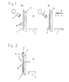
- Fig. 4 den Querschnitt mit Lichtgang eines konkaven Lamellenprofils;
- Fig. 5 den Querschnitt durch ein erfindungsgemässes Lamellenprofil; und
- Fig. 6 den Querschnitt durch einen erfindungsgemässen Storenbehang;
- Fig. 7 die schematische Ansicht eines Storenbehanges mit Knick-Lamellen.
- Fig. 1 shows schematically a conventional blind curtain;
- Fig. 2 shows schematically an inventive blind with rocker;
- 3 shows the cross section with light path of a convex lamella profile;
- Fig. 4 shows the cross section with light path of a konka ven slat profile;
- 5 shows the cross section through a lamella profile according to the invention; and
- 6 shows the cross section through a blind curtain according to the invention;
- Fig. 7 is a schematic view of a blind with buckling slats.
Fig. 1 a) zeigt einen herkömmlichen Storenbehang 1 mit senkrecht zur Bewegungsrichtung stehenden Lamellen 2, vor einem Fenster 3 angeordnet. Hinter dem Fenster ist ein Arbeitsplatz 4 angedeutet. Die von der Sonne stammenden direkten Sonnenstrahlen 5 können durch die Lücken zwischen den Lamellen 2 in den Raum 6 einstrahlen. Dabei kommt es zu störender Blendung am Arbeitsplatz 4. Insbesondere am Arbeitsplatz befindliche Bildschirme, in der Figur nicht dargestellt, können starke Reflektionen aufweisen, was ein Arbeiten am Bildschirm verunmöglichen kann.1 a) shows a conventional
Um dem abzuhelfen, müssen die Lamellen, wie in Fig. 1 b) dargestellt, mit ihren Oberseiten gegen die Lichtstrahlung 5 gerichtet werden. Damit wird praktisch die gesamte direkte Lichteinstrahlung abgeschirmt und die Blendung und Reflektionen am Arbeitsplatz 4 verschwinden. Damit wird aber der Raum 6 ungenügend ausgeleuchtet, da praktisch auch keine indirekte Lichtstrahlung mehr in den Raum durchgelassen wird, und es ist notwendig, den Raum 6 mittels Kunstlicht 7, beispielsweise Leuchtstoffröhren, zusätzlich zu beleuchten.To remedy this, the lamellae, as shown in FIG. 1 b), must be directed with their upper sides against the
Diese unbefriedigende Situation kann mittels eines erfindungsgemässen Storens, wie in Fig. 2 schematisch dargestellt, behoben werden. Die Lamellen 2' im oberen Bereich des Behanges stehen senkrecht zur Bewegungsrichtung des Behanges. Damit kann in diesem Bereich die Lichteinstrahlung zu einem grossen Teil in den Raum 6 gelangen und leuchtet damit den Deckenbereich des Raumes 6 auch bis in vom Fenster 3 weiter entfernte Bereiche aus. Im unteren Bereich des Behanges 1 sind die Lamellen 2" mit ihrer Oberseite gegen die Lichteinstrahlung ausgerichtet, und schirmen damit den unteren Bereich des Raumes 6, und damit insbesondere den Arbeitsplatz 4, gegen diese direkte Lichteinstrahlung ab. Damit ist der Arbeitsplatz 4 von störenden Blendungen und Reflektionen verschont, bleibt aber trotzdem genügend ausgeleuchtet, wodurch zusätzliche Kunstlichtbeleuchtung überflüssig wird. Insbesondere wird dadurch auch der weiter vom Fenster entfernte Bereich des Raumes noch genügend durch natürliches Licht ausgeleuchtet. Damit entstehen angenehmere Arbeitsverhältnisse am Arbeitsplatz 4 als bei herkömmlichen Storenanordnungen.This unsatisfactory situation can be remedied by means of a store according to the invention, as shown schematically in FIG. 2. The slats 2 'in the upper region of the curtain are perpendicular to the direction of movement of the curtain. A large part of the light radiation can thus enter the
Als optimale Anordnung hat sich eine Unterteilung des Storenbehanges von ca. 30% der Behangfläche für den oberen Bereich und entsprechend ca. 70% der Behangfläche für den unteren Bereich erwiesen. Dabei sollen die Lamellen im oberen Bereich, wie in den Figuren angedeutet, etwa horizontal, d.h.senkrecht zur Bewegungsrichtung des Behanges, und im unteren Bereich mit einem Winkel von 60°, zwischen der Aussenfläche der Lamellen und der Bewegungsrichtung des Behanges, ausgerichtet sein. Dies wird beispielsweise durch Verändern der Bandabschnitte 8 auf einer Seite des Behanges zwischen zwei Lamellen erreicht.A subdivision of the blind curtain has proven to be an optimal arrangement of approximately 30% of the curtain area for the upper area and correspondingly approximately 70% of the curtain area for the lower area. The slats in the upper area, as indicated in the figures, should be approximately horizontal, i.e. perpendicular to the direction of movement of the curtain, and in the lower area at an angle of 60 ° between the outer surface of the slats and the direction of movement of the curtain. This is achieved, for example, by changing the
Wenn vorteilhafterweise eine bekannte Wippenkonstruktion 9, wie beispielsweise aus DE P 37 31 374 oder DE P 38 43 750 bekannt, mit welcher die Lamellen gemeinsam verstellt werden können, mit den erfindungsgemässen Massnahmen eingesetzt wird, kann der Behang optimal auf die herrschenden Lichtverhältnisse eingestellt werden, ohne dass zusätzliche Bedienmittel vorgesehen sein müssen. Dabei wird die in der Figur 2 dargestellte Lage vorteilhafterweise jweils vor einer Auf- oder Abwärtsbewegung des Behanges durch die Wippe 9 erstellt, damit die Lamellen 2',2" nicht durch enges Anliegen an die Raffbänder 10 mit diesen verklemmen können. Damit ist es möglich, den Behang auch nur teilweise Abzusenken oder Anzuheben, wobei die Lamellen in einem Bereich des Behanges sogar vollständig geschlossen sein können.If a known rocker construction 9, such as known from DE P 37 31 374 or DE P 38 43 750, with which the slats can be adjusted together, is advantageously used with the measures according to the invention, the curtain can be optimally adjusted to the prevailing light conditions, without additional operating means having to be provided. The position shown in FIG. 2 is advantageously created by the rocker 9 before the curtain 9 moves up or down so that the
In Figur 3 ist schematisch der Lichtstrahlengang durch eine Lamellenanordnung 11,11' mit konvexer Profilform dargestellt. In Figur4 ist entsprechend der Fig. 3 der Lichtstrahlengang durch eine Lamellenanordnung mit konkaver Profilform 12,12' zum Vergleich dargestellt. In Fig. 3 a) resp. 4 a) ist eine horizontale Strahlung dargestellt. Hier wird bei beiden Profilformen derjenige Anteil, der durch die Lamellenprofiltiefe verdeckt ist, welche bei beiden Profilen dieselbe ist, abgeschirmt. Bei der in den Figuren 3 b) und 4 b) dargestellten freien oder direkten Einstrahlung wird ebenfalls bei beiden Profilformen derselbe Teil abgedeckt. In den Figuren 3 c) und 4 c) wird der Reflexionsanteil dargestellt. Hier zeigt sich nun beim in Fig. 4 c) dargestellten konkaven Profil ein grösserAnteil als beim konvexen Profil wie in Fig. 3 c) dargestellt.FIG. 3 schematically shows the light beam path through a
Eine erfindungsgemässe Profilform ist in Fig. 5 dargestellt. Hierwerden die vorgängig beschriebenen Eigenschaften der unterschiedlichen Profilformen optimal ausgenutzt. Das Profil 13 weist einen vorderen konkaven Bereich 13' und einen hinteren konvexen Bereich 13" auf. Der konkave Bereich 13' ist derjenige, welcher gegen die Besonnungs- resp. Bestrahlungsseite, d.h. gegen die Aussenseite eines Gebäudes, gerichtet ist. Dabei ist das Verhältnis der beiden Profiltiefen T1 und T2 vorzugsweise 2 : 1. Die beiden Profilbereiche 13' und 13" sind vorzugsweise derart gewählt, dass ein Verhältnis vom vorderen Bereich 13'zum hinteren Bereich 13" von vorzugsweise 3 : 2, mit B1 und B2 bezeichnet, erzielt wird.A profile shape according to the invention is shown in FIG. 5. Here, the properties of the different profile shapes described above are optimally used. The
Figur 6 zeigt schematisch den Querschnitt durch einen erfindungsgemässen Storenbehang, wobei die Lamellen 13 hier in horizontaler Stellung ausgerichtet dargestellt sind. Der Storenbehang wird von der Aussenseite A her von der Sonne angestrahlt und leitet die Strahlung wie vorgängig beschrieben zur Innenseite I durch, resp. schirmt sie ab. Ein solcher Storenbehang kann beispielsweise vor oder hinter einem Fenster angeordnet sein.Figure 6 shows schematically the cross section through a blind according to the invention, the
Durch diese erfindungsgemässe Profilform wird einerseits eine sehr grosse Lichtausbeute durch Streulicht gegen das Rauminnere erreicht, und andererseits die direkte Einstrahlung sehr stark reduziert. Der reflektierte Anteil der Lichtstrahlung ist dabei geringer als bei einer konvex gebogenen Profilform, womit eine grössere Lichtausbeute erreicht wird. Gleichzeitig werden auch optisch störenden Schattenbildungen auf der Profilunterseite von übereinander angeordneten Lamellen durch den konvexen Abschluss vermieden.With this profile shape according to the invention, on the one hand a very high light yield is achieved by scattered light against the interior of the room, and on the other hand the direct irradiation is greatly reduced. The reflected portion of the light radiation is lower than with a convexly curved profile shape, which achieves a greater light yield. At the same time, optically disturbing shadows on the underside of the profile of slats arranged one above the other are avoided by the convex end.
In Figur 7 ist schematisch die Seitenansicht eines Ausschnittes eines Storenbehanges mit Lamellenprofilen 14 dargestellt, welche eine Knick 14' im Bereich der Durchführung der Raffbänder 15 aufweisen. Die Lamellen 14 sind hier in einer nahezu volltändig geschlossenen Stellung dargestellt. Diese Stellung wird durch Betätigen der Bandabsschnitt 16, 17 beispielsweise mittels einer Wippenkonstruktion auf herkömmliche Weise eingestellt. Die Raffbänder 15 können nun dank dem Knick 14' problemlos durch die Lamellen 14 gleiten. Damit wird insbesondere beim Herablassen der Storenbehanges vermieden, dass die Lamellen 14 an den Raffbändern 15 verklemmen. Dies ist insbesondere bei elektrisch betätigten Lamellenstoren von Vorteil, da diese oft unbeaufsichtigt betätigt werden und eine Fehlfunktion oft nicht erkannt wird oder sogar der Antrieb beschädigt werden kann.FIG. 7 schematically shows the side view of a section of a blind curtain with lamella profiles 14, which have a kink 14 'in the area where the shirring tapes 15 pass through. The slats 14 are shown here in an almost completely closed position. This position is set in a conventional manner by actuating the band sections 16, 17, for example by means of a rocker construction. Thanks to the kink 14 ', the gathering belts 15 can now slide easily through the slats 14. In this way, in particular when lowering the blind curtain, it is avoided that the slats 14 jam on the gathering belts 15. This is particularly advantageous in the case of electrically operated slat blinds, since these are often operated unattended and a malfunction is often not recognized or the drive can even be damaged.
Claims (15)
Applications Claiming Priority (8)
| Application Number | Priority Date | Filing Date | Title |
|---|---|---|---|
| CH122892 | 1992-04-14 | ||
| CH1227/92 | 1992-04-14 | ||
| CH1228/92 | 1992-04-14 | ||
| CH122792 | 1992-04-14 | ||
| DE9208341U DE9208341U1 (en) | 1992-04-14 | 1992-06-23 | |
| DE9208341U | 1992-06-23 | ||
| DE4220891 | 1992-06-25 | ||
| DE19924220891 DE4220891A1 (en) | 1992-06-25 | 1992-06-25 | Lamella shutters for shading rooms |
Publications (2)
| Publication Number | Publication Date |
|---|---|
| EP0566524A2 true EP0566524A2 (en) | 1993-10-20 |
| EP0566524A3 EP0566524A3 (en) | 1993-11-10 |
Family
ID=27428123
Family Applications (1)
| Application Number | Title | Priority Date | Filing Date |
|---|---|---|---|
| EP19930810065 Withdrawn EP0566524A3 (en) | 1992-04-14 | 1993-02-02 | Lamellar blind for shading of rooms |
Country Status (1)
| Country | Link |
|---|---|
| EP (1) | EP0566524A3 (en) |
Cited By (5)
| Publication number | Priority date | Publication date | Assignee | Title |
|---|---|---|---|---|
| EP0743421A2 (en) * | 1995-05-19 | 1996-11-20 | Hunter Douglas Industries B.V. | A method and apparatus for producing a plurality of sequentially arranged edge contoured slats |
| GB2303661A (en) * | 1995-07-26 | 1997-02-26 | John Garth Reynolds | S-shaped slat for a vertical blind |
| US6123137A (en) * | 1997-08-28 | 2000-09-26 | Hunter Douglas International N.V. | Combined multiple-glazed window and light-control assembly |
| AU2009100562B4 (en) * | 2009-06-10 | 2009-09-03 | Liftmaster Electronics Pty Ltd | Blind slat |
| EP2154325A2 (en) | 2008-08-12 | 2010-02-17 | Roma Rolladensysteme GmbH | Shade device |
Citations (7)
| Publication number | Priority date | Publication date | Assignee | Title |
|---|---|---|---|---|
| FR1135369A (en) * | 1955-07-15 | 1957-04-26 | Improvement of interior and exterior blinds with adjustable slats known as Venetian blinds | |
| FR1220085A (en) * | 1958-12-30 | 1960-05-23 | Improvements to light alloy blades for Venetian blinds | |
| US3122954A (en) * | 1964-03-03 | Venetian blind slats | ||
| DE1509494A1 (en) * | 1964-10-20 | 1969-05-14 | Hedberg Klas Wilhelm Rune | Adjustment device for slat blinds |
| FR2212481A1 (en) * | 1972-12-27 | 1974-07-26 | Schenker Storen Maschf | |
| DE3731374A1 (en) * | 1987-07-16 | 1989-02-02 | Baumann Rolladen | Blind-tilting device, and Venetian blind equipped therewith |
| US4865106A (en) * | 1987-10-26 | 1989-09-12 | Wichelman Karl F | Heat insulator window shade |
-
1993
- 1993-02-02 EP EP19930810065 patent/EP0566524A3/en not_active Withdrawn
Patent Citations (7)
| Publication number | Priority date | Publication date | Assignee | Title |
|---|---|---|---|---|
| US3122954A (en) * | 1964-03-03 | Venetian blind slats | ||
| FR1135369A (en) * | 1955-07-15 | 1957-04-26 | Improvement of interior and exterior blinds with adjustable slats known as Venetian blinds | |
| FR1220085A (en) * | 1958-12-30 | 1960-05-23 | Improvements to light alloy blades for Venetian blinds | |
| DE1509494A1 (en) * | 1964-10-20 | 1969-05-14 | Hedberg Klas Wilhelm Rune | Adjustment device for slat blinds |
| FR2212481A1 (en) * | 1972-12-27 | 1974-07-26 | Schenker Storen Maschf | |
| DE3731374A1 (en) * | 1987-07-16 | 1989-02-02 | Baumann Rolladen | Blind-tilting device, and Venetian blind equipped therewith |
| US4865106A (en) * | 1987-10-26 | 1989-09-12 | Wichelman Karl F | Heat insulator window shade |
Cited By (8)
| Publication number | Priority date | Publication date | Assignee | Title |
|---|---|---|---|---|
| EP0743421A2 (en) * | 1995-05-19 | 1996-11-20 | Hunter Douglas Industries B.V. | A method and apparatus for producing a plurality of sequentially arranged edge contoured slats |
| EP0743421B1 (en) * | 1995-05-19 | 2003-07-16 | Hunter Douglas Industries B.V. | A method and apparatus for producing a plurality of sequentially arranged edge contoured slats |
| GB2303661A (en) * | 1995-07-26 | 1997-02-26 | John Garth Reynolds | S-shaped slat for a vertical blind |
| US6123137A (en) * | 1997-08-28 | 2000-09-26 | Hunter Douglas International N.V. | Combined multiple-glazed window and light-control assembly |
| US6397917B1 (en) | 1997-08-28 | 2002-06-04 | Hunter Douglas Industries B.V. | Combined multiple-glazed window and light-control assembly |
| EP2154325A2 (en) | 2008-08-12 | 2010-02-17 | Roma Rolladensysteme GmbH | Shade device |
| DE102008037358A1 (en) * | 2008-08-12 | 2010-02-25 | Roma Rolladensysteme Gmbh | shading device |
| AU2009100562B4 (en) * | 2009-06-10 | 2009-09-03 | Liftmaster Electronics Pty Ltd | Blind slat |
Also Published As
| Publication number | Publication date |
|---|---|
| EP0566524A3 (en) | 1993-11-10 |
Similar Documents
| Publication | Publication Date | Title |
|---|---|---|
| EP0606543B1 (en) | Glare protection device | |
| EP1787003A1 (en) | Slats for a sun protection blind | |
| EP0566524A2 (en) | Lamellar blind for shading of rooms | |
| AT394883B (en) | SLATER BLINDS | |
| EP0609541B1 (en) | Venetian blind | |
| DE10260711B4 (en) | Glare-free blinds | |
| DE3625365A1 (en) | Turning device for a slatted blind which can be gathered up and has three slat positions | |
| DE19929138A1 (en) | Sunshade-blind arrangement | |
| EP0303107B1 (en) | Antiglare device | |
| DE19537190B4 (en) | Vertical blind slat | |
| EP1243743B1 (en) | Lamella for a blind screen | |
| DE4220891A1 (en) | Lamella shutters for shading rooms | |
| DE4336763A1 (en) | Device for avoiding sunrays and similar sources of light shining in directly through windows | |
| EP1717403B1 (en) | Venetian blind | |
| AT521340B1 (en) | Glare-free daylight slat blinds | |
| EP0969179A2 (en) | Lamella for a slatted blind | |
| EP3992412A1 (en) | Shading blind with slats with sections | |
| AT408896B (en) | light deflection system | |
| DE19845424A1 (en) | Sun guard for incident sunlight comprizes constant-spaced reflecting slats pivoting round axis to track and direct sun rays into or clear of building. | |
| DE202011101237U1 (en) | Slat for sun protection and daylight steering systems | |
| EP3992413A1 (en) | Shading blind | |
| DE19837984C1 (en) | Strip blind for window | |
| DE10235840B4 (en) | Slat curtain for windows | |
| DE3523524C2 (en) | ||
| DE19844576A1 (en) | Blind slat is curved to give transparent reflecting and absorbing parts and rides on cords along edges. |
Legal Events
| Date | Code | Title | Description |
|---|---|---|---|
| PUAI | Public reference made under article 153(3) epc to a published international application that has entered the european phase |
Free format text: ORIGINAL CODE: 0009012 |
|
| PUAL | Search report despatched |
Free format text: ORIGINAL CODE: 0009013 |
|
| AK | Designated contracting states |
Kind code of ref document: A2 Designated state(s): AT BE CH DE DK ES FR GB GR IE IT LI LU MC NL PT SE |
|
| AK | Designated contracting states |
Kind code of ref document: A3 Designated state(s): AT BE CH DE DK ES FR GB GR IE IT LI LU MC NL PT SE |
|
| RBV | Designated contracting states (corrected) |
Designated state(s): AT BE CH DE FR LI NL |
|
| 17P | Request for examination filed |
Effective date: 19940505 |
|
| 17Q | First examination report despatched |
Effective date: 19960222 |
|
| STAA | Information on the status of an ep patent application or granted ep patent |
Free format text: STATUS: THE APPLICATION IS DEEMED TO BE WITHDRAWN |
|
| 18D | Application deemed to be withdrawn |
Effective date: 19960904 |