EP0566035A1 - Dispositif pour séparer des systèmes dispersés liquide-liquide et liquide-solide - Google Patents
Dispositif pour séparer des systèmes dispersés liquide-liquide et liquide-solide Download PDFInfo
- Publication number
- EP0566035A1 EP0566035A1 EP93105842A EP93105842A EP0566035A1 EP 0566035 A1 EP0566035 A1 EP 0566035A1 EP 93105842 A EP93105842 A EP 93105842A EP 93105842 A EP93105842 A EP 93105842A EP 0566035 A1 EP0566035 A1 EP 0566035A1
- Authority
- EP
- European Patent Office
- Prior art keywords
- liquid
- separating elements
- permeable
- horizontal
- impermeable
- Prior art date
- Legal status (The legal status is an assumption and is not a legal conclusion. Google has not performed a legal analysis and makes no representation as to the accuracy of the status listed.)
- Granted
Links
Images
Classifications
-
- B—PERFORMING OPERATIONS; TRANSPORTING
- B01—PHYSICAL OR CHEMICAL PROCESSES OR APPARATUS IN GENERAL
- B01D—SEPARATION
- B01D17/00—Separation of liquids, not provided for elsewhere, e.g. by thermal diffusion
- B01D17/02—Separation of non-miscible liquids
- B01D17/0208—Separation of non-miscible liquids by sedimentation
- B01D17/0211—Separation of non-miscible liquids by sedimentation with baffles
-
- B—PERFORMING OPERATIONS; TRANSPORTING
- B01—PHYSICAL OR CHEMICAL PROCESSES OR APPARATUS IN GENERAL
- B01D—SEPARATION
- B01D17/00—Separation of liquids, not provided for elsewhere, e.g. by thermal diffusion
- B01D17/02—Separation of non-miscible liquids
- B01D17/04—Breaking emulsions
- B01D17/045—Breaking emulsions with coalescers
Definitions
- the invention relates to a device for separating disperse liquid-liquid and liquid-solid substance systems according to the preamble of claim 1.
- coalescence separators are known for separating suspended, sinkable solids and / or light droplets from a liquid, usually water, by sinking or coalescing the dispersed phases.
- Coalescence separators are containers in which the liquid flows through barriers, in which the dispersed phases are given the opportunity to separate.
- a known device of the type mentioned at the beginning comprises at least one barrier made up of a plurality of lamella plates packed together to form a plate stack from lamellae alternately inclined in opposite directions at the same angle to the vertical and connected to one another at their adjacent longitudinal edges and delimiting flow channels (DE 38 24 295 C2). If sinkable or sinkable and floatable substances are to be separated from the liquid, then the lamella plates are arranged so that the individual lamellae are inclined at an angle of 60 degrees to the vertical. The accumulating sinkable particles can slide down on the lamellae in order to sink down over the longitudinal edges of the lamellae facing the flow downward to the bottom of the container or into a special collecting container.
- Substances dispersed to form light droplets can accumulate on the undersides of the lamellae, where they form a thin layer that rises as a result of the natural buoyancy in order to be detached in larger droplets on the longitudinal edges of the plates, which in turn rise into the storage space .
- Plate separators of this type only work with very small ones Flow speeds are satisfactory.
- Coalescence barriers made of mats have the disadvantageous property of acting as a filter for sinkable solids in addition to the coalescence effect for light droplets. Since the liquids to be clarified generally contain not only light liquids dispersed as droplets, but often also dirt particles as suspended matter, the mats can become clogged over time due to the filter effect. This has the consequence that during maintenance work, which also includes cleaning the coalescing mats after pumping out the liquid, suspended matter and light liquid remain in the mats, which then often collapse and can only be disposed of as special waste.
- the invention is based on the object of a device of the type specified at the outset with regard to the simultaneous separation of solid and liquid dispersed fractions from a liquid regardless of the hydraulic load on the liquid Optimize cross-section.
- the optimization of the separation function of the barrier according to the invention results from the sensible combination of permeable and impermeable separation elements. Since plate separators work with very high efficiency at very small finite speeds and in a different droplet size range than mat separators, which require a certain minimum speed of the liquid, the advantage of the independence of the separation function from the hydraulic load results in a wide range.
- the angular inclination of the impermeable separating elements and the arrangement and design of the drip edges give rise to relatively large drops which quickly rise to the surface of the liquid.
- the inclined to horizontal arrangement of the permeable separating elements enables the velocity vector of the liquid passing through them to be aligned with the buoyancy of the drops and promotes separation in the shortest possible way, since the drops are, in a sense, inevitably led into the upper regions of the liquid.
- the angle of attack of the impermeable and permeable separating elements the liquid flow can be guided in such a way that the continuous phase with the lowest proportion of dispersed phase can be drawn off in the outlet area.
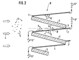
- FIG. 2 shows a schematic cross section through a barrier B designed according to the invention.
- This barrier B consists of impermeable separating elements, namely coalescence plates 1 made of metal or plastic, and permeable separating elements, namely coalescing mats 2 made of fiber material, which are each flat and alternately inclined in opposite directions to the horizontal.
- the separating elements 1 and 2 are connected to one another at their adjacent longitudinal edges 3.
- the mats 2 are inclined at an angle of inclination alpha of 0 to 45 degrees to the horizontal and the plates 1 are also inclined at an angle of inclination Beta between 0 and 60 degrees to the horizontal against the direction of flow, which is indicated by the arrows 4.
- the sinkable solid particles 5 arriving with the liquid flow of the disperse system with the speed vector 4 can drop when entering the barrier B as a result of a reduction in the flow speed; they come to the surface of the inclined Plates 1, from which they slide as a result of gravity (5 ') and sink to the ground via their front edge (5'').
- the droplets 6 floating in the liquid coalesce as they flow through the mats 3 to form larger drops 6 '.
- These form a film on the underside of the plates 1, which as a result of the buoyancy forces moves upwards along the inclined surface and detaches at the drip edge 7 in the form of lamellae and large drops 6 ′′.
- the horizontal to inclined arrangement of the mats 2 in connection with their flow from bottom to top has the advantage that the sinkable solid particles 5 have the opportunity to sink to the ground before entering the actual barrier B, so that a load on the mats 2 is avoided by the otherwise observed filter effect.
- the coalescence of the droplets 6 within the mats 2 is significantly improved in that the velocity vector of the liquid and the buoyancy of the drops act essentially in the same direction. This results in an excellent separation effect with significantly reduced maintenance.
- the most diverse materials can be used with regard to their wettability, both for the plates 1 and for the mats 2, depending on the separation task and material system.
- the drop size can also be influenced by appropriate choice of the angular inclination of the plates 1 and / or mats 2 and design of the drip edges. While in the upper part of FIG. 2 the drip edge 7 is arranged to a certain extent in continuation of the plates 1 with respect to the corner formation 3 “below”, the drip edges 7 ′, as indicated in the lower part, can also be “above”.
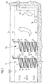
- Fig. 1 is a longitudinal section for a separator shown, in which two barriers B1 and B2 are arranged one behind the other.
- the two barriers B1 and B2 are used in a container 10, for example made of concrete, in an upright position so that the flow cross section for the liquid to be clarified is completed.
- the bottom plate 1 'in each case adjoins the container base 11, while the top plate 1''merges into a vertical partition wall 12 which extends beyond the mirror 13 of the continuous phase.
- the separated drop liquid 14 floats on the continuous phase, from where it can be drawn off in a suitable manner.
Landscapes
- Physics & Mathematics (AREA)
- Thermal Sciences (AREA)
- Chemical & Material Sciences (AREA)
- Chemical Kinetics & Catalysis (AREA)
- Separation Of Solids By Using Liquids Or Pneumatic Power (AREA)
- Physical Or Chemical Processes And Apparatus (AREA)
- Separation Using Semi-Permeable Membranes (AREA)
- Treatment Of Sludge (AREA)
- Centrifugal Separators (AREA)
- Removal Of Floating Material (AREA)
Applications Claiming Priority (2)
| Application Number | Priority Date | Filing Date | Title |
|---|---|---|---|
| DE4212449A DE4212449A1 (de) | 1992-04-14 | 1992-04-14 | Vorrichtung zum Abscheiden suspendierter Stoffe aus einer Flüssigkeit |
| DE4212449 | 1992-04-14 |
Publications (2)
| Publication Number | Publication Date |
|---|---|
| EP0566035A1 true EP0566035A1 (fr) | 1993-10-20 |
| EP0566035B1 EP0566035B1 (fr) | 1995-04-19 |
Family
ID=6456781
Family Applications (1)
| Application Number | Title | Priority Date | Filing Date |
|---|---|---|---|
| EP93105842A Expired - Lifetime EP0566035B1 (fr) | 1992-04-14 | 1993-04-08 | Dispositif pour séparer des systèmes dispersés liquide-liquide et liquide-solide |
Country Status (5)
| Country | Link |
|---|---|
| EP (1) | EP0566035B1 (fr) |
| AT (1) | ATE121310T1 (fr) |
| DE (2) | DE4212449A1 (fr) |
| DK (1) | DK0566035T3 (fr) |
| ES (1) | ES2073315T3 (fr) |
Cited By (4)
| Publication number | Priority date | Publication date | Assignee | Title |
|---|---|---|---|---|
| DE4434271A1 (de) * | 1994-09-24 | 1996-03-28 | Buderus Guss Gmbh | Koaleszenzelement zum Einfügen in einen Leichtflüssigkeitsabscheider |
| EP0800849A1 (fr) * | 1996-03-07 | 1997-10-15 | Dyckerhoff & Widmann Ag | Dispositif de séparation de systèmes dispersées liquide-liquide et liquide-solide |
| EP1559465A1 (fr) * | 2004-01-27 | 2005-08-03 | Services Petroliers Schlumberger | Système de récupération de gouttelettes fines |
| GB2436303A (en) * | 2006-03-24 | 2007-09-26 | Zeta Dynamics Ltd | Vertical calming baffle |
Citations (5)
| Publication number | Priority date | Publication date | Assignee | Title |
|---|---|---|---|---|
| US1758743A (en) * | 1929-04-05 | 1930-05-13 | Harman Jay Floyd | Oil and water separator |
| DE1169895B (de) * | 1959-02-28 | 1964-05-14 | Boewe Boehler & Weber K G Masc | Wasserabscheider fuer die Trennung eines Loesungsmittel-Wasser-Gemisches |
| US3152196A (en) * | 1960-12-21 | 1964-10-06 | Shell Oil Co | Stage efficiency in liquid-liquid extraction process |
| US3957656A (en) * | 1972-04-28 | 1976-05-18 | Castelli Joseph L | Plate separator for fluid mixtures |
| DE3824295A1 (de) * | 1988-07-18 | 1990-01-25 | Preussag Ag Bauwesen | Klaervorrichtung |
Family Cites Families (3)
| Publication number | Priority date | Publication date | Assignee | Title |
|---|---|---|---|---|
| DE54037C (de) * | P. A. MAIGNEN in London | Vorrichtung zum Reinigen von Wasser und anderen Flüssigkeiten von festen Bestandteilen | ||
| US4278545A (en) * | 1979-09-12 | 1981-07-14 | The Bendix Corporation | Apparatus for separating solids and liquid components |
| US4897206A (en) * | 1988-11-30 | 1990-01-30 | Facet Quantek, Inc. | Bidirectionally corrugated plate separator for fluid mixtures |
-
1992
- 1992-04-14 DE DE4212449A patent/DE4212449A1/de not_active Withdrawn
-
1993
- 1993-04-08 EP EP93105842A patent/EP0566035B1/fr not_active Expired - Lifetime
- 1993-04-08 DK DK93105842.4T patent/DK0566035T3/da active
- 1993-04-08 ES ES93105842T patent/ES2073315T3/es not_active Expired - Lifetime
- 1993-04-08 AT AT93105842T patent/ATE121310T1/de not_active IP Right Cessation
- 1993-04-08 DE DE59300147T patent/DE59300147D1/de not_active Expired - Fee Related
Patent Citations (5)
| Publication number | Priority date | Publication date | Assignee | Title |
|---|---|---|---|---|
| US1758743A (en) * | 1929-04-05 | 1930-05-13 | Harman Jay Floyd | Oil and water separator |
| DE1169895B (de) * | 1959-02-28 | 1964-05-14 | Boewe Boehler & Weber K G Masc | Wasserabscheider fuer die Trennung eines Loesungsmittel-Wasser-Gemisches |
| US3152196A (en) * | 1960-12-21 | 1964-10-06 | Shell Oil Co | Stage efficiency in liquid-liquid extraction process |
| US3957656A (en) * | 1972-04-28 | 1976-05-18 | Castelli Joseph L | Plate separator for fluid mixtures |
| DE3824295A1 (de) * | 1988-07-18 | 1990-01-25 | Preussag Ag Bauwesen | Klaervorrichtung |
Cited By (7)
| Publication number | Priority date | Publication date | Assignee | Title |
|---|---|---|---|---|
| DE4434271A1 (de) * | 1994-09-24 | 1996-03-28 | Buderus Guss Gmbh | Koaleszenzelement zum Einfügen in einen Leichtflüssigkeitsabscheider |
| EP0800849A1 (fr) * | 1996-03-07 | 1997-10-15 | Dyckerhoff & Widmann Ag | Dispositif de séparation de systèmes dispersées liquide-liquide et liquide-solide |
| EP1559465A1 (fr) * | 2004-01-27 | 2005-08-03 | Services Petroliers Schlumberger | Système de récupération de gouttelettes fines |
| WO2005070514A1 (fr) * | 2004-01-27 | 2005-08-04 | Services Petroliers Schlumberger | Systeme de recuperation de petites gouttelettes |
| EA012976B1 (ru) * | 2004-01-27 | 2010-02-26 | Шлюмбергер Текнолоджи Б.В. | Аппарат для разделения водно/углеводородной эмульсионной жидкости и способ извлечения углеводородной жидкости и очищенной водной жидкости |
| US7678286B2 (en) | 2004-01-27 | 2010-03-16 | Schlumberger Technology Corporation | Small droplets recovery system |
| GB2436303A (en) * | 2006-03-24 | 2007-09-26 | Zeta Dynamics Ltd | Vertical calming baffle |
Also Published As
| Publication number | Publication date |
|---|---|
| DE4212449A1 (de) | 1993-10-28 |
| DE59300147D1 (de) | 1995-05-24 |
| DK0566035T3 (da) | 1995-09-04 |
| ATE121310T1 (de) | 1995-05-15 |
| EP0566035B1 (fr) | 1995-04-19 |
| ES2073315T3 (es) | 1995-08-01 |
Similar Documents
| Publication | Publication Date | Title |
|---|---|---|
| DE69532329T2 (de) | Trennungsvorrichtung und trennungsmethode | |
| DE3210972C2 (de) | Sinkscheider für Kunststoffgemische | |
| DE2725811A1 (de) | Klaervorrichtung | |
| DE1929974A1 (de) | Schwerkraftabsetzbehaelter | |
| DE2029721A1 (de) | Patrone zum Vereinigen von feinen Oltropfchen | |
| DE2706642C3 (de) | Vorrichtung zum Trennen zweier Flüssigkeiten von unterschiedlichem spezifischem Gewicht | |
| DE3538843A1 (de) | Vorrichtung zur kontinuierlichen trennung von fluessigen gemischen | |
| DE69816068T2 (de) | Vorrichtung zur abtrennung von feststoffen aus einer flüssigkeit | |
| DE2707872A1 (de) | Absetztank | |
| DE2535824A1 (de) | Abscheidevorrichtung zum abscheiden von substanzen aus einer zu reinigenden fluessigkeit | |
| DE3333777A1 (de) | Apparatur zur trennung von in fluessigkeit enthaltenen substanzen | |
| EP0118021A2 (fr) | Séparateur de liquides légers | |
| EP0566035B1 (fr) | Dispositif pour séparer des systèmes dispersés liquide-liquide et liquide-solide | |
| EP0048239B1 (fr) | Appareil de contre-courant diphasé | |
| DE69716839T2 (de) | Behälter zum Entgasen von Wasser | |
| EP2142272B1 (fr) | Dispositif de flottation doté d'une plaque perforée | |
| DE2905017A1 (de) | Horizontal durchstroemter stehender oelabscheider und verfahren zum abscheiden von oel aus einem gemisch aus oel und wasser | |
| EP0522265B1 (fr) | Séparateur de liquide | |
| DE19850320C2 (de) | Kompaktanlage für die mechanische Reinigung von Abwasser | |
| EP0820796A2 (fr) | Séparateur d'huile | |
| DE2627598C2 (de) | Vorrichtung zum Abscheiden und Rückhalten nichtgelöster Kohlenwasserstoffe aus Wasser | |
| DE3707285A1 (de) | Verfahren zum abscheiden von leichtfluessigkeiten vorwiegend aus fliessgewaessern | |
| DE29600692U1 (de) | Einrichtung zum Trennen von als heterogenes Stoffgemisch vorliegenden Stoffen | |
| DE8411291U1 (de) | Vorrichtung zum filtern von abscheidbare verunreinigungen enthaltenden abwaessern | |
| DE4434271C2 (de) | Stapelbares Koaleszenzelement zum Einfügen in einen Leichtflüssigkeitsabscheider |
Legal Events
| Date | Code | Title | Description |
|---|---|---|---|
| PUAI | Public reference made under article 153(3) epc to a published international application that has entered the european phase |
Free format text: ORIGINAL CODE: 0009012 |
|
| 17P | Request for examination filed |
Effective date: 19930807 |
|
| AK | Designated contracting states |
Kind code of ref document: A1 Designated state(s): AT BE CH DE DK ES FR GB GR IE IT LI LU NL PT SE |
|
| 17Q | First examination report despatched |
Effective date: 19931129 |
|
| GRAA | (expected) grant |
Free format text: ORIGINAL CODE: 0009210 |
|
| AK | Designated contracting states |
Kind code of ref document: B1 Designated state(s): AT BE CH DE DK ES FR GB GR IE IT LI LU NL PT SE |
|
| PG25 | Lapsed in a contracting state [announced via postgrant information from national office to epo] |
Ref country code: GB Effective date: 19950419 |
|
| REF | Corresponds to: |
Ref document number: 121310 Country of ref document: AT Date of ref document: 19950515 Kind code of ref document: T |
|
| REG | Reference to a national code |
Ref country code: IE Ref legal event code: FG4D Free format text: 63616 |
|
| REF | Corresponds to: |
Ref document number: 59300147 Country of ref document: DE Date of ref document: 19950524 |
|
| ITF | It: translation for a ep patent filed | ||
| ET | Fr: translation filed | ||
| PG25 | Lapsed in a contracting state [announced via postgrant information from national office to epo] |
Ref country code: SE Effective date: 19950719 Ref country code: PT Effective date: 19950719 |
|
| REG | Reference to a national code |
Ref country code: ES Ref legal event code: FG2A Ref document number: 2073315 Country of ref document: ES Kind code of ref document: T3 |
|
| REG | Reference to a national code |
Ref country code: GR Ref legal event code: FG4A Free format text: 3016528 |
|
| REG | Reference to a national code |
Ref country code: DK Ref legal event code: T3 |
|
| GBV | Gb: ep patent (uk) treated as always having been void in accordance with gb section 77(7)/1977 [no translation filed] |
Effective date: 19950419 |
|
| PG25 | Lapsed in a contracting state [announced via postgrant information from national office to epo] |
Ref country code: IE Free format text: LAPSE BECAUSE OF NON-PAYMENT OF DUE FEES Effective date: 19951101 |
|
| REG | Reference to a national code |
Ref country code: IE Ref legal event code: FD4D Ref document number: 63616 Country of ref document: IE |
|
| PLBE | No opposition filed within time limit |
Free format text: ORIGINAL CODE: 0009261 |
|
| 26N | No opposition filed | ||
| PGFP | Annual fee paid to national office [announced via postgrant information from national office to epo] |
Ref country code: GR Payment date: 19980430 Year of fee payment: 6 |
|
| PGFP | Annual fee paid to national office [announced via postgrant information from national office to epo] |
Ref country code: ES Payment date: 19990419 Year of fee payment: 7 |
|
| PGFP | Annual fee paid to national office [announced via postgrant information from national office to epo] |
Ref country code: FR Payment date: 19990420 Year of fee payment: 7 |
|
| PG25 | Lapsed in a contracting state [announced via postgrant information from national office to epo] |
Ref country code: GR Free format text: LAPSE BECAUSE OF NON-PAYMENT OF DUE FEES Effective date: 19990430 |
|
| PG25 | Lapsed in a contracting state [announced via postgrant information from national office to epo] |
Ref country code: ES Free format text: LAPSE BECAUSE OF NON-PAYMENT OF DUE FEES Effective date: 20000410 |
|
| PG25 | Lapsed in a contracting state [announced via postgrant information from national office to epo] |
Ref country code: FR Free format text: LAPSE BECAUSE OF NON-PAYMENT OF DUE FEES Effective date: 20001229 |
|
| REG | Reference to a national code |
Ref country code: FR Ref legal event code: ST |
|
| PGFP | Annual fee paid to national office [announced via postgrant information from national office to epo] |
Ref country code: AT Payment date: 20010323 Year of fee payment: 9 |
|
| PGFP | Annual fee paid to national office [announced via postgrant information from national office to epo] |
Ref country code: CH Payment date: 20010606 Year of fee payment: 9 |
|
| PG25 | Lapsed in a contracting state [announced via postgrant information from national office to epo] |
Ref country code: AT Free format text: LAPSE BECAUSE OF NON-PAYMENT OF DUE FEES Effective date: 20020408 |
|
| PGFP | Annual fee paid to national office [announced via postgrant information from national office to epo] |
Ref country code: NL Payment date: 20020416 Year of fee payment: 10 |
|
| PGFP | Annual fee paid to national office [announced via postgrant information from national office to epo] |
Ref country code: LU Payment date: 20020419 Year of fee payment: 10 Ref country code: BE Payment date: 20020419 Year of fee payment: 10 |
|
| PGFP | Annual fee paid to national office [announced via postgrant information from national office to epo] |
Ref country code: DK Payment date: 20020422 Year of fee payment: 10 |
|
| PG25 | Lapsed in a contracting state [announced via postgrant information from national office to epo] |
Ref country code: LI Free format text: LAPSE BECAUSE OF NON-PAYMENT OF DUE FEES Effective date: 20020430 Ref country code: CH Free format text: LAPSE BECAUSE OF NON-PAYMENT OF DUE FEES Effective date: 20020430 |
|
| REG | Reference to a national code |
Ref country code: CH Ref legal event code: PL |
|
| REG | Reference to a national code |
Ref country code: ES Ref legal event code: FD2A Effective date: 20030203 |
|
| PG25 | Lapsed in a contracting state [announced via postgrant information from national office to epo] |
Ref country code: LU Free format text: LAPSE BECAUSE OF NON-PAYMENT OF DUE FEES Effective date: 20030408 |
|
| PG25 | Lapsed in a contracting state [announced via postgrant information from national office to epo] |
Ref country code: DK Free format text: LAPSE BECAUSE OF NON-PAYMENT OF DUE FEES Effective date: 20030430 Ref country code: BE Free format text: LAPSE BECAUSE OF NON-PAYMENT OF DUE FEES Effective date: 20030430 |
|
| BERE | Be: lapsed |
Owner name: *DYCKERHOFF & WIDMANN A.G. Effective date: 20030430 |
|
| PG25 | Lapsed in a contracting state [announced via postgrant information from national office to epo] |
Ref country code: NL Free format text: LAPSE BECAUSE OF NON-PAYMENT OF DUE FEES Effective date: 20031101 |
|
| NLV4 | Nl: lapsed or anulled due to non-payment of the annual fee |
Effective date: 20031101 |
|
| REG | Reference to a national code |
Ref country code: DK Ref legal event code: EBP |
|
| PG25 | Lapsed in a contracting state [announced via postgrant information from national office to epo] |
Ref country code: IT Free format text: LAPSE BECAUSE OF NON-PAYMENT OF DUE FEES Effective date: 20050408 |
|
| PGFP | Annual fee paid to national office [announced via postgrant information from national office to epo] |
Ref country code: DE Payment date: 20060613 Year of fee payment: 14 |
|
| PG25 | Lapsed in a contracting state [announced via postgrant information from national office to epo] |
Ref country code: DE Free format text: LAPSE BECAUSE OF NON-PAYMENT OF DUE FEES Effective date: 20071101 |