EP0566008A1 - Frein à disque actionné par air comprimé - Google Patents
Frein à disque actionné par air comprimé Download PDFInfo
- Publication number
- EP0566008A1 EP0566008A1 EP93105709A EP93105709A EP0566008A1 EP 0566008 A1 EP0566008 A1 EP 0566008A1 EP 93105709 A EP93105709 A EP 93105709A EP 93105709 A EP93105709 A EP 93105709A EP 0566008 A1 EP0566008 A1 EP 0566008A1
- Authority
- EP
- European Patent Office
- Prior art keywords
- brake
- disc
- adjusting
- separating device
- air
- Prior art date
- Legal status (The legal status is an assumption and is not a legal conclusion. Google has not performed a legal analysis and makes no representation as to the accuracy of the status listed.)
- Granted
Links
- 230000005540 biological transmission Effects 0.000 claims abstract description 7
- 230000007257 malfunction Effects 0.000 abstract 1
- 238000012423 maintenance Methods 0.000 description 6
- 230000006378 damage Effects 0.000 description 3
- 238000005299 abrasion Methods 0.000 description 1
- 230000006835 compression Effects 0.000 description 1
- 238000007906 compression Methods 0.000 description 1
- 238000010276 construction Methods 0.000 description 1
- 230000000694 effects Effects 0.000 description 1
- 238000009434 installation Methods 0.000 description 1
- 238000000034 method Methods 0.000 description 1
- 230000003313 weakening effect Effects 0.000 description 1
Images


Classifications
-
- F—MECHANICAL ENGINEERING; LIGHTING; HEATING; WEAPONS; BLASTING
- F16—ENGINEERING ELEMENTS AND UNITS; GENERAL MEASURES FOR PRODUCING AND MAINTAINING EFFECTIVE FUNCTIONING OF MACHINES OR INSTALLATIONS; THERMAL INSULATION IN GENERAL
- F16D—COUPLINGS FOR TRANSMITTING ROTATION; CLUTCHES; BRAKES
- F16D65/00—Parts or details
- F16D65/14—Actuating mechanisms for brakes; Means for initiating operation at a predetermined position
- F16D65/16—Actuating mechanisms for brakes; Means for initiating operation at a predetermined position arranged in or on the brake
- F16D65/18—Actuating mechanisms for brakes; Means for initiating operation at a predetermined position arranged in or on the brake adapted for drawing members together, e.g. for disc brakes
- F16D65/183—Actuating mechanisms for brakes; Means for initiating operation at a predetermined position arranged in or on the brake adapted for drawing members together, e.g. for disc brakes with force-transmitting members arranged side by side acting on a spot type force-applying member
-
- F—MECHANICAL ENGINEERING; LIGHTING; HEATING; WEAPONS; BLASTING
- F16—ENGINEERING ELEMENTS AND UNITS; GENERAL MEASURES FOR PRODUCING AND MAINTAINING EFFECTIVE FUNCTIONING OF MACHINES OR INSTALLATIONS; THERMAL INSULATION IN GENERAL
- F16D—COUPLINGS FOR TRANSMITTING ROTATION; CLUTCHES; BRAKES
- F16D65/00—Parts or details
- F16D65/38—Slack adjusters
- F16D65/40—Slack adjusters mechanical
- F16D65/52—Slack adjusters mechanical self-acting in one direction for adjusting excessive play
- F16D65/56—Slack adjusters mechanical self-acting in one direction for adjusting excessive play with screw-thread and nut
- F16D65/567—Slack adjusters mechanical self-acting in one direction for adjusting excessive play with screw-thread and nut for mounting on a disc brake
- F16D65/568—Slack adjusters mechanical self-acting in one direction for adjusting excessive play with screw-thread and nut for mounting on a disc brake for synchronous adjustment of actuators arranged in parallel
-
- F—MECHANICAL ENGINEERING; LIGHTING; HEATING; WEAPONS; BLASTING
- F16—ENGINEERING ELEMENTS AND UNITS; GENERAL MEASURES FOR PRODUCING AND MAINTAINING EFFECTIVE FUNCTIONING OF MACHINES OR INSTALLATIONS; THERMAL INSULATION IN GENERAL
- F16D—COUPLINGS FOR TRANSMITTING ROTATION; CLUTCHES; BRAKES
- F16D2121/00—Type of actuator operation force
- F16D2121/14—Mechanical
-
- F—MECHANICAL ENGINEERING; LIGHTING; HEATING; WEAPONS; BLASTING
- F16—ENGINEERING ELEMENTS AND UNITS; GENERAL MEASURES FOR PRODUCING AND MAINTAINING EFFECTIVE FUNCTIONING OF MACHINES OR INSTALLATIONS; THERMAL INSULATION IN GENERAL
- F16D—COUPLINGS FOR TRANSMITTING ROTATION; CLUTCHES; BRAKES
- F16D2125/00—Components of actuators
- F16D2125/18—Mechanical mechanisms
- F16D2125/20—Mechanical mechanisms converting rotation to linear movement or vice versa
- F16D2125/22—Mechanical mechanisms converting rotation to linear movement or vice versa acting transversely to the axis of rotation
- F16D2125/26—Cranks
-
- F—MECHANICAL ENGINEERING; LIGHTING; HEATING; WEAPONS; BLASTING
- F16—ENGINEERING ELEMENTS AND UNITS; GENERAL MEASURES FOR PRODUCING AND MAINTAINING EFFECTIVE FUNCTIONING OF MACHINES OR INSTALLATIONS; THERMAL INSULATION IN GENERAL
- F16D—COUPLINGS FOR TRANSMITTING ROTATION; CLUTCHES; BRAKES
- F16D2125/00—Components of actuators
- F16D2125/18—Mechanical mechanisms
- F16D2125/58—Mechanical mechanisms transmitting linear movement
- F16D2125/64—Levers
Definitions
- the invention relates to a compressed air-operated disc brake according to the preamble of claim 1, which is provided in particular for road vehicles and preferably for commercial vehicles.
- Air-operated or pneumatic disc brakes of the generic type are known, for example, from DE-OS 37 16 202 and from unpublished DE-OS 40 32 885 .
- a brake disc is encompassed by a brake caliper displaceably mounted in the axial direction, a compressed air-operated application device being arranged on one side of the brake caliper, upon actuation of which a brake shoe located on this side of the brake disc is pressed against it, whereupon the brake caliper due to the Reaction forces shifts in the opposite direction and thereby also presses a brake shoe on the opposite side against the brake disc.
- the application device has a rotary lever as an actuating element, which is pivotably mounted about an axis of rotation running parallel to the plane of the brake disc.
- the rotary lever here lies on its side facing the brake disc by means of an eccentric approximately longitudinally against a cross-piece extending parallel to the axis of rotation, which is displaceably guided with respect to the brake disc and in which at least one adjusting spindle having an external thread is screwed adjustably into an associated internal thread of the cross-beam is, the adjusting spindle over a on her brake disc-side end of the pressure piece acts on the brake side of the brake caliper displaceably mounted with respect to the brake disc.
- an adjusting device is provided that is non-rotatably coupled to the adjusting spindle and that each time the rotary lever is actuated, the adjusting spindle is adjusted by a certain amount Angle rotates if the brake shoe is not yet in contact with the brake disc after overcoming the target air gap.
- the adjusting device has, as functionally essential parts, a free-wheel and a slip clutch, among other things.
- the adjusting device has at its end facing away from the brake disc, for example in the form of a hexagon, which, by means of a suitable socket wrench, enables the adjusting device (and thus the adjusting spindle coupled therewith) to be rotated counter to the adjusting direction.
- the invention has for its object to develop a compressed air operated disc brake according to the preamble of claim 1 such that a brake failure caused by improper implementation of the pad change can be largely avoided.
- a separating device responding to a certain limit torque is provided, which in the simplest case is a predetermined breaking point.
- the separating device in which the force transmission path is formed by a shaft formed with the rotary head, the separating device is formed as a notch in the region of the shaft adjoining the rotary head.
- This configuration of the separating device can be implemented with little effort, in particular in the case of a predetermined breaking point designed as a notch, and moreover allows a very exact setting of the desired limit torque, which is of course selected taking into account the maximum load capacity of the functional elements of the adjusting device.
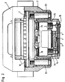
- a (internally ventilated) brake disc 1 which is fastened to an axle of a commercial vehicle, which is not specified in more detail, is encompassed by a brake caliper 2.
- the brake caliper 2 is mounted on the vehicle in an axially displaceable manner with respect to the brake disc 1 by means of a rigid guide bearing 52 and by means of a compensating bearing 51.
- the structure and function of the brake caliper are known, so that a detailed explanation is unnecessary.
- a (two-spindle) application device schematically designated by the reference number 3 is arranged on the right side in FIG. 1 or the lower side in FIG. 2 of the brake disk 1.
- a substantially semicircular pivot bearing 30 is provided, the axis of rotation of which runs parallel to the plane of the brake disc 1 and which receives the correspondingly rounded region of a pivot lever 4, so that the pivot lever 4 can be pivoted parallel to the plane of the brake disc 1.
- a brake cylinder 40 which is only shown schematically, is provided, which engages with a piston in a suitably shaped recess in an actuating arm 4a of the rotary lever 4.
- the actuating arm 4a of the rotary lever 4 is consequently moved from its rest position into the position indicated in broken lines in FIG. 1. It should be noted that the actuation of the rotary lever 4 can of course also take place via a brake linkage, so that the brake cylinder 40 can optionally be placed at a different location if the available installation space for the disc brake or its application device is limited.
- the side of the rotary lever 4 facing away from the half-shell-shaped rotary bearing 30 is coupled via an eccentric 6 serving as a cam to a cross member 7 which is located within the Brake caliper 2 extends substantially parallel to the axis of rotation of the brake disc 1 and is slidably mounted in this plane.
- the cross member 7 At its end facing the brake disc 1, the cross member 7 has a blind hole-like recess, which is surrounded by a tubular extension projecting in the direction of the brake disc 1.
- This approach of the cross member 7 is in a corresponding recess of the brake caliper 2 perpendicular to the plane of the brake disc 1 while maintaining such a play that the cross member 7 can perform slight pivoting movements in the plane of the drawing.
- a spiral spring 78 is arranged within the recess, which is clamped between the cross member 7 and the end of the brake caliper 2 facing the brake disc 1 and thereby prestresses the cross member 7 towards the rotary lever 4.
- the cross member 7 has on both sides a bore provided with an internal thread, in each of which an adjusting spindle 72 or 73 is adjustably screwed, the external thread in FIG a correspondingly shaped internal thread of the cross member 7 is guided.
- a conically widening pressure piece 70 or 71 is fastened. Since the two adjusting spindles 72 and 73 extend perpendicular to the plane of the brake disc 1 due to their arrangement in the crossmember 7, the pressure pieces 70 and 71 rest with their flat ends on a brake shoe 10.
- the brake shoe 10 is guided in particular in the circumferential direction to the brake disc 1 by means of brackets not shown transversely to the brake disc 1, wherein the brackets can either be assigned to the brake caliper 2 or a brake carrier.
- An adjusting device 74 is arranged in the interior of the adjusting spindle 72 and is rotationally fixed as a result of an axial toothing is coupled to the adjusting spindle 72 and is displaceable in the axial direction.
- the adjusting device 74 is rotated by a certain angular amount each time the rotary lever 4 is actuated, which ensures continuous readjustment of the brake.
- a gear engages in a corresponding axial toothing of the opposite adjusting spindle 73, which gear is coupled via a shaft to a synchronization device 75, which rotates the internal gear and thus the spindle 73 synchronously with the adjusting device 74. This ensures that the pressure piece 71 is adjusted synchronously with the pressure piece 70.
- the adjusting spindle is arranged, for example, in the middle of the cross member 7, while the eccentric 6 and the bearing of the cross member 7 having the compression spring are each produced in duplicate are provided on both sides of the central adjusting spindle.
- the adjusting device 74 has on its upper, i.e. End facing away from the brake disc on a rotary head in the form of a hexagon 19; this is coupled via a shaft 16 to the inner functional elements, which are only indicated schematically, such that rotating the hexagon in the counter-tightening direction leads to the adjusting spindle in FIG. 3 moving upward into its starting position, so that a new brake shoe 10 is installed can be.
- the cross member 7 is therefore pressed against the biasing force of the spiral spring 78 by this distance to the brake disc 1.
- the pressure pieces 70 and 71 fastened to the cross member 7 via the adjusting spindles 72 and 73 consequently press the brake shoe 10 against the brake disk 1 while overcoming the clearance (which in practice is approximately 0.4 mm). If the actuating arm 4a continues to move is pivoted to the left, the brake caliper moves due to the force exerted on the brake disc 1 in FIG. 1 to the right, so that finally the left brake shoe 10 is also pressed against the brake disc 1.
- the adjusting device 74 ensures that the adjusting spindles 72 and 73 rotate until the clearance reaches its desired value. In this way it is ensured that the disc brake remains functional until the brake shoes 10 are completely worn.
- the adjusting spindles 72 and 73 can reach their limit position facing away from the brake disk, in which their rotation is inhibited, as a result of which a strong moment is built up between the adjusting spindle and the adjusting device which is coupled to it in a rotationally fixed manner; when this moment is in the form of a separating device shown in FIG. 3, formed in a shaft 16 connecting the hexagon 19 to the functional elements a predetermined breaking point SB exceeds the predetermined limit value, the shaft 16 breaks at the predetermined breaking point SB, so that destruction of the parts necessary for the safe operation of the brake can be reliably prevented.
- the predetermined breaking point SB can be produced in a simple manner by means of a notch in the shaft or another material weakening.
- the predetermined breaking point SB in the embodiment shown is expediently arranged outside the housing cover of the application device 3; this ensures that all parts necessary for the operation of the brake, in particular also a link chain of the synchronization device 75, continue to be operated correctly despite the response of the predetermined breaking point SB.
- the separating device As a slip clutch that responds at a predetermined torque.
- the force transmission takes place by means of a rotatably mounted lever 4, which acts on a crossbar 7 via an eccentric;
- the principle of the invention can of course also be used in other application devices, for example in those in which the force transmission takes place by means of an expansion wedge or a ball ramp.
- the invention is not limited to the shown embodiments of the adjusting spindle and adjusting device; the separating device can rather be used with all actuating elements whose axial position relative to the brake disc increases with increasing Pad wear is changed by a suitable drive device.
Landscapes
- Engineering & Computer Science (AREA)
- General Engineering & Computer Science (AREA)
- Mechanical Engineering (AREA)
- Braking Arrangements (AREA)
Priority Applications (1)
| Application Number | Priority Date | Filing Date | Title |
|---|---|---|---|
| DE9312120U DE9312120U1 (de) | 1992-04-13 | 1993-04-06 | Druckluftbetätigte Scheibenbremse |
Applications Claiming Priority (2)
| Application Number | Priority Date | Filing Date | Title |
|---|---|---|---|
| DE4212405A DE4212405C2 (de) | 1992-04-13 | 1992-04-13 | Druckluftbetätigte Scheibenbremse |
| DE4212405 | 1992-04-13 |
Publications (2)
| Publication Number | Publication Date |
|---|---|
| EP0566008A1 true EP0566008A1 (fr) | 1993-10-20 |
| EP0566008B1 EP0566008B1 (fr) | 1996-02-07 |
Family
ID=6456752
Family Applications (1)
| Application Number | Title | Priority Date | Filing Date |
|---|---|---|---|
| EP93105709A Revoked EP0566008B1 (fr) | 1992-04-13 | 1993-04-06 | Frein à disque actionné par air comprimé |
Country Status (2)
| Country | Link |
|---|---|
| EP (1) | EP0566008B1 (fr) |
| DE (2) | DE4212405C2 (fr) |
Cited By (15)
| Publication number | Priority date | Publication date | Assignee | Title |
|---|---|---|---|---|
| DE19729024C1 (de) * | 1997-07-08 | 1999-01-28 | Knorr Bremse Systeme | Verschleißnachstellvorrichtung für Scheibenbremsen |
| WO2000071906A1 (fr) | 1999-05-21 | 2000-11-30 | Knorr-Bremse Systeme für Nutzfahrzeuge GmbH | Dispositif de rattrapage d'usure des garnitures de freins |
| DE19632917B4 (de) * | 1995-08-18 | 2004-11-18 | Meritor Technology, Llc | Bremsenjustiermechanismus |
| DE102007019440A1 (de) | 2007-04-25 | 2008-10-30 | Knorr-Bremse Systeme für Nutzfahrzeuge GmbH | Scheibenbremse mit Lösespindel für die Nachstelleinrichtung |
| DE102008029314A1 (de) | 2007-10-25 | 2009-04-30 | Knorr-Bremse Systeme für Nutzfahrzeuge GmbH | Fahrzeugbremse |
| EP2083190A2 (fr) | 2008-01-22 | 2009-07-29 | KNORR-BREMSE Systeme für Nutzfahrzeuge GmbH | Frein à disque doté d'un accouplement à patinage pour le dispositif de réglage |
| DE102008005455A1 (de) | 2008-01-22 | 2009-07-30 | Knorr-Bremse Systeme für Nutzfahrzeuge GmbH | Scheibenbremse mit Sicherheitskupplung für die Nachstelleinrichtung |
| US7694784B2 (en) | 2005-03-24 | 2010-04-13 | Knorr-Bremse Systeme Fuer Nutzfahrzeuge Gmbh | Adjusting apparatus for a pneumatically actuated disc brake |
| EP2292945A1 (fr) | 2009-09-02 | 2011-03-09 | KNORR-BREMSE Systeme für Nutzfahrzeuge GmbH | Frein à disque doté d'un accouplement à patinage pour le dispositif de réglage |
| EP3091246A1 (fr) | 2015-05-04 | 2016-11-09 | KNORR-BREMSE Systeme für Nutzfahrzeuge GmbH | Frein à disque |
| WO2017144441A2 (fr) | 2016-02-26 | 2017-08-31 | Knorr-Bremse Systeme für Nutzfahrzeuge GmbH | Garniture de frein à disque et jeu de garnitures de frein |
| EP3269993A1 (fr) | 2016-07-15 | 2018-01-17 | KNORR-BREMSE Systeme für Nutzfahrzeuge GmbH | Frein à disque pour un véhicule utilitaire |
| EP3296585A1 (fr) | 2016-09-20 | 2018-03-21 | KNORR-BREMSE Systeme für Nutzfahrzeuge GmbH | Frein à disque et procédé d'utilisation d'un frein à disque |
| DE102016117779A1 (de) | 2016-09-21 | 2018-03-22 | Knorr-Bremse Systeme für Nutzfahrzeuge GmbH | Bremsscheibe für eine Scheibenbremse und Scheibenbremse |
| DE102021126280A1 (de) | 2021-10-11 | 2023-04-13 | Knorr-Bremse Systeme für Nutzfahrzeuge GmbH | Scheibenbremse mit einer Synchronisationsmechanik |
Families Citing this family (5)
| Publication number | Priority date | Publication date | Assignee | Title |
|---|---|---|---|---|
| DE4314720A1 (de) * | 1993-05-04 | 1994-11-10 | Knorr Bremse Ag | Druckluftbetätigte Scheibenbremse |
| DE19906227B4 (de) * | 1999-02-15 | 2004-05-13 | Knorr-Bremse Systeme für Nutzfahrzeuge GmbH | Scheibenbremse für Fahrzeuge und Steuerungsverfahren |
| DE19907958B4 (de) * | 1999-02-24 | 2004-04-22 | Knorr-Bremse Systeme für Nutzfahrzeuge GmbH | Elektromechanisch über ein Zykloidengetriebe betätigte Scheibenbremse für Fahrzeuge |
| ATE344402T1 (de) | 2000-08-17 | 2006-11-15 | Knorr Bremse Systeme | Scheibenbremse mit einem zuspannsystem mit drehhebel |
| DE102005035266A1 (de) * | 2005-07-28 | 2007-02-01 | Bpw Bergische Achsen Kg | Betätigungsvorrichtung für die Zustelleinrichtung einer Fahrzeugbremse, vorzugsweise einer Scheibenbremse |
Citations (2)
| Publication number | Priority date | Publication date | Assignee | Title |
|---|---|---|---|---|
| DE2341781A1 (de) * | 1972-08-24 | 1974-03-07 | Twin Disc Inc | Kupplung zur uebertragung eines begrenzten drehmomentes |
| DE4034165A1 (de) * | 1990-06-07 | 1991-12-12 | Knorr Bremse Ag | Scheibenbremse fuer fahrzeuge |
Family Cites Families (2)
| Publication number | Priority date | Publication date | Assignee | Title |
|---|---|---|---|---|
| DE3716202C3 (de) * | 1987-05-14 | 2000-03-09 | Knorr Bremse Systeme | Scheibenbremse für Fahrzeuge |
| DE4032885A1 (de) * | 1990-10-17 | 1992-04-23 | Knorr Bremse Ag | Scheibenbremse fuer fahrzeuge, insbesondere strassenfahrzeuge |
-
1992
- 1992-04-13 DE DE4212405A patent/DE4212405C2/de not_active Expired - Lifetime
-
1993
- 1993-04-06 DE DE59301574T patent/DE59301574D1/de not_active Expired - Lifetime
- 1993-04-06 EP EP93105709A patent/EP0566008B1/fr not_active Revoked
Patent Citations (2)
| Publication number | Priority date | Publication date | Assignee | Title |
|---|---|---|---|---|
| DE2341781A1 (de) * | 1972-08-24 | 1974-03-07 | Twin Disc Inc | Kupplung zur uebertragung eines begrenzten drehmomentes |
| DE4034165A1 (de) * | 1990-06-07 | 1991-12-12 | Knorr Bremse Ag | Scheibenbremse fuer fahrzeuge |
Cited By (36)
| Publication number | Priority date | Publication date | Assignee | Title |
|---|---|---|---|---|
| DE19632917B4 (de) * | 1995-08-18 | 2004-11-18 | Meritor Technology, Llc | Bremsenjustiermechanismus |
| DE19729024C1 (de) * | 1997-07-08 | 1999-01-28 | Knorr Bremse Systeme | Verschleißnachstellvorrichtung für Scheibenbremsen |
| WO2000071906A1 (fr) | 1999-05-21 | 2000-11-30 | Knorr-Bremse Systeme für Nutzfahrzeuge GmbH | Dispositif de rattrapage d'usure des garnitures de freins |
| US6820727B1 (en) | 1999-05-21 | 2004-11-23 | Knorr-Bremse Systeme Fuer Nutzfahrzeuge Gmbh | Wear adjustment device for a brake |
| CZ297090B6 (cs) * | 1999-05-21 | 2006-09-13 | Knorr-Bremse Systeme für Nutzfahrzeuge GmbH | Nastavovací zarízení opotrebení pro brzdu |
| US7694784B2 (en) | 2005-03-24 | 2010-04-13 | Knorr-Bremse Systeme Fuer Nutzfahrzeuge Gmbh | Adjusting apparatus for a pneumatically actuated disc brake |
| DE102007019440B4 (de) * | 2007-04-25 | 2009-08-06 | Knorr-Bremse Systeme für Nutzfahrzeuge GmbH | Scheibenbremse mit Lösespindel für die Nachstelleinrichtung |
| US9382955B2 (en) | 2007-04-25 | 2016-07-05 | Knorr-Bremse Systeme Fuer Nutzfahrzeuge Gmbh | Disc brake having a release spindle for the adjustment device |
| WO2008131864A2 (fr) | 2007-04-25 | 2008-11-06 | Knorr-Bremse Systeme für Nutzfahrzeuge GmbH | Frein à disque à tige de desserrage pour dispositif de rattrapage d'usure |
| DE102007019440A1 (de) | 2007-04-25 | 2008-10-30 | Knorr-Bremse Systeme für Nutzfahrzeuge GmbH | Scheibenbremse mit Lösespindel für die Nachstelleinrichtung |
| DE102008029314A1 (de) | 2007-10-25 | 2009-04-30 | Knorr-Bremse Systeme für Nutzfahrzeuge GmbH | Fahrzeugbremse |
| EP2055981A2 (fr) | 2007-10-25 | 2009-05-06 | KNORR-BREMSE Systeme für Nutzfahrzeuge GmbH | Frein de véhicule |
| EP2083190A2 (fr) | 2008-01-22 | 2009-07-29 | KNORR-BREMSE Systeme für Nutzfahrzeuge GmbH | Frein à disque doté d'un accouplement à patinage pour le dispositif de réglage |
| DE102008005454A1 (de) | 2008-01-22 | 2009-07-30 | Knorr-Bremse Systeme für Nutzfahrzeuge GmbH | Scheibenbremse mit Rutschkupplung für die Nachstelleinrichtung |
| DE102008005455A1 (de) | 2008-01-22 | 2009-07-30 | Knorr-Bremse Systeme für Nutzfahrzeuge GmbH | Scheibenbremse mit Sicherheitskupplung für die Nachstelleinrichtung |
| DE102008005454B4 (de) * | 2008-01-22 | 2010-03-25 | Knorr-Bremse Systeme für Nutzfahrzeuge GmbH | Scheibenbremse mit Rutschkupplung für die Nachstelleinrichtung |
| DE102008005455B4 (de) * | 2008-01-22 | 2010-04-08 | Knorr-Bremse Systeme für Nutzfahrzeuge GmbH | Scheibenbremse mit Sicherheitskupplung für die Nachstelleinrichtung |
| EP2083190A3 (fr) * | 2008-01-22 | 2011-03-09 | KNORR-BREMSE Systeme für Nutzfahrzeuge GmbH | Frein à disque doté d'un accouplement à patinage pour le dispositif de réglage |
| EP2083189A3 (fr) * | 2008-01-22 | 2011-03-09 | KNORR-BREMSE Systeme für Nutzfahrzeuge GmbH | Frein à disque doté d'un accouplement de sécurité pour le dispositif de réglage |
| EP2292945A1 (fr) | 2009-09-02 | 2011-03-09 | KNORR-BREMSE Systeme für Nutzfahrzeuge GmbH | Frein à disque doté d'un accouplement à patinage pour le dispositif de réglage |
| DE102009039800A1 (de) | 2009-09-02 | 2011-03-10 | Knorr-Bremse Systeme für Nutzfahrzeuge GmbH | Scheibenbremse mit Rutschkupplung für die Nachstelleinrichtung |
| DE102015106841B4 (de) | 2015-05-04 | 2020-06-04 | Knorr-Bremse Systeme für Nutzfahrzeuge GmbH | Scheibenbremse |
| EP3091246A1 (fr) | 2015-05-04 | 2016-11-09 | KNORR-BREMSE Systeme für Nutzfahrzeuge GmbH | Frein à disque |
| DE102015106841A1 (de) | 2015-05-04 | 2016-11-10 | Knorr-Bremse Systeme für Nutzfahrzeuge GmbH | Scheibenbremse |
| US10927909B2 (en) | 2016-02-26 | 2021-02-23 | Knorr-Bremse Systeme Fuer Nutzfahrzeuge Gmbh | Brake lining of a disk brake and brake pad set |
| DE102016103396A1 (de) | 2016-02-26 | 2017-08-31 | Knorr-Bremse Systeme für Nutzfahrzeuge GmbH | Bremsbelag einer Scheibenbremse und Bremsbelagsatz |
| WO2017144441A2 (fr) | 2016-02-26 | 2017-08-31 | Knorr-Bremse Systeme für Nutzfahrzeuge GmbH | Garniture de frein à disque et jeu de garnitures de frein |
| DE102016103396B4 (de) | 2016-02-26 | 2022-09-15 | Knorr-Bremse Systeme für Nutzfahrzeuge GmbH | Bremsbelag einer Scheibenbremse und Bremsbelagsatz |
| EP3269993A1 (fr) | 2016-07-15 | 2018-01-17 | KNORR-BREMSE Systeme für Nutzfahrzeuge GmbH | Frein à disque pour un véhicule utilitaire |
| WO2018010989A1 (fr) | 2016-07-15 | 2018-01-18 | Knorr-Bremse Systeme für Nutzfahrzeuge GmbH | Frein à disque destiné à un véhicule utilitaire |
| EP3296585A1 (fr) | 2016-09-20 | 2018-03-21 | KNORR-BREMSE Systeme für Nutzfahrzeuge GmbH | Frein à disque et procédé d'utilisation d'un frein à disque |
| WO2018054780A1 (fr) | 2016-09-20 | 2018-03-29 | Knorr-Bremse Systeme für Nutzfahrzeuge GmbH | Frein à disque et procédé pour actionner un frein à disque |
| DE102016117779A1 (de) | 2016-09-21 | 2018-03-22 | Knorr-Bremse Systeme für Nutzfahrzeuge GmbH | Bremsscheibe für eine Scheibenbremse und Scheibenbremse |
| WO2018054816A1 (fr) | 2016-09-21 | 2018-03-29 | Knorr-Bremse Systeme für Nutzfahrzeuge GmbH | Disque de frein pour frein a disque, et frein a disque |
| DE102021126280A1 (de) | 2021-10-11 | 2023-04-13 | Knorr-Bremse Systeme für Nutzfahrzeuge GmbH | Scheibenbremse mit einer Synchronisationsmechanik |
| WO2023061815A1 (fr) | 2021-10-11 | 2023-04-20 | Knorr-Bremse Systeme für Nutzfahrzeuge GmbH | Frein à disque doté d'un mécanisme de synchronisation |
Also Published As
| Publication number | Publication date |
|---|---|
| DE4212405C2 (de) | 2000-02-10 |
| EP0566008B1 (fr) | 1996-02-07 |
| DE59301574D1 (de) | 1996-03-21 |
| DE4212405A1 (de) | 1993-10-14 |
Similar Documents
| Publication | Publication Date | Title |
|---|---|---|
| EP0566008B1 (fr) | Frein à disque actionné par air comprimé | |
| EP1039166B1 (fr) | Frein à disque actionné par air comprimé | |
| EP0688404B1 (fr) | Frein a disque pneumatique | |
| EP0739459B1 (fr) | Dispositif d'application d'un frein a disque, en particulier pour vehicules utilitaires lourds | |
| DE69301652T2 (de) | Selbsttätige Nachstelleinrichtung für den Bremshebel einer S-Nocken-Fahrzeug-Trommelbremse | |
| EP0659242B1 (fr) | Frein a disque commande par air comprime | |
| WO2006099938A1 (fr) | Dispositif de rattrapage de jeu pour un frein a disque a commande pneumatique | |
| DE2354322C2 (de) | Hydraulisch und mechanisch wirkende Bremsbetätigungsvorrichtung | |
| DE102005027915A1 (de) | Scheibenbremse mit elektromotorisch betriebenen Nachstellvorrichtungen und Verfahren zur Durchführung einer Parkbremsung | |
| DE2362283A1 (de) | Spielnachstell-vorrichtung | |
| EP0636218B1 (fr) | Frein a disque a air comprime | |
| EP0534989B1 (fr) | Frein a disque pour vehicules | |
| WO1993021458A1 (fr) | Detecteur de jeu pour un frein a disque a air comprime | |
| DE2261843B2 (de) | Selbsttaetige, doppeltwirkende bremsgestaengenachstelleinrichtung im bremsgestaenge, insbesondere von schienenfahrzeugen | |
| EP0636220B1 (fr) | Frein a disque a air comprime | |
| EP0566007B1 (fr) | Frein à disque actionné par air comprimé | |
| EP0654615A1 (fr) | Appui d'une garniture de frein pour un frein à disque | |
| DE4226143A1 (de) | Druckgesteuerte axial verschiebbare Nachstellvorrichtung | |
| DE3621926A1 (de) | Automatische nachstellvorrichtung | |
| EP0852301B1 (fr) | Frein à disque | |
| DE9312120U1 (de) | Druckluftbetätigte Scheibenbremse | |
| DE1480038C (de) | Selbsttätige Nachstellvorrichtung für ein Fahrzeugbremssystem | |
| DE9218248U1 (de) | Lüftspieldetektor für eine druckluftbetätigte Scheibenbremse | |
| DE9312126U1 (de) | Druckluftbetätigte Scheibenbremse | |
| DE9312347U1 (de) | Druckluftbetätigte Scheibenbremse |
Legal Events
| Date | Code | Title | Description |
|---|---|---|---|
| PUAI | Public reference made under article 153(3) epc to a published international application that has entered the european phase |
Free format text: ORIGINAL CODE: 0009012 |
|
| AK | Designated contracting states |
Kind code of ref document: A1 Designated state(s): DE ES GB GR IT NL SE |
|
| 17P | Request for examination filed |
Effective date: 19931125 |
|
| 17Q | First examination report despatched |
Effective date: 19940622 |
|
| RAP1 | Party data changed (applicant data changed or rights of an application transferred) |
Owner name: KNORR-BREMSE SYSTEME FUER NUTZFAHRZEUGE GMBH |
|
| RBV | Designated contracting states (corrected) |
Designated state(s): DE ES FR GB IT NL SE |
|
| ITF | It: translation for a ep patent filed | ||
| GRAA | (expected) grant |
Free format text: ORIGINAL CODE: 0009210 |
|
| AK | Designated contracting states |
Kind code of ref document: B1 Designated state(s): DE ES FR GB IT NL SE |
|
| PG25 | Lapsed in a contracting state [announced via postgrant information from national office to epo] |
Ref country code: NL Free format text: LAPSE BECAUSE OF FAILURE TO SUBMIT A TRANSLATION OF THE DESCRIPTION OR TO PAY THE FEE WITHIN THE PRESCRIBED TIME-LIMIT Effective date: 19960207 Ref country code: GB Effective date: 19960207 Ref country code: FR Effective date: 19960207 Ref country code: ES Free format text: THE PATENT HAS BEEN ANNULLED BY A DECISION OF A NATIONAL AUTHORITY Effective date: 19960207 |
|
| REF | Corresponds to: |
Ref document number: 59301574 Country of ref document: DE Date of ref document: 19960321 |
|
| PGFP | Annual fee paid to national office [announced via postgrant information from national office to epo] |
Ref country code: SE Payment date: 19960424 Year of fee payment: 4 |
|
| NLV1 | Nl: lapsed or annulled due to failure to fulfill the requirements of art. 29p and 29m of the patents act | ||
| EN | Fr: translation not filed | ||
| GBV | Gb: ep patent (uk) treated as always having been void in accordance with gb section 77(7)/1977 [no translation filed] |
Effective date: 19960207 |
|
| PLBQ | Unpublished change to opponent data |
Free format text: ORIGINAL CODE: EPIDOS OPPO |
|
| PLBI | Opposition filed |
Free format text: ORIGINAL CODE: 0009260 |
|
| PLBF | Reply of patent proprietor to notice(s) of opposition |
Free format text: ORIGINAL CODE: EPIDOS OBSO |
|
| 26 | Opposition filed |
Opponent name: LUCAS INDUSTRIES PLC Effective date: 19961105 |
|
| PG25 | Lapsed in a contracting state [announced via postgrant information from national office to epo] |
Ref country code: SE Effective date: 19970407 |
|
| PLBF | Reply of patent proprietor to notice(s) of opposition |
Free format text: ORIGINAL CODE: EPIDOS OBSO |
|
| PLBF | Reply of patent proprietor to notice(s) of opposition |
Free format text: ORIGINAL CODE: EPIDOS OBSO |
|
| EUG | Se: european patent has lapsed |
Ref document number: 93105709.5 |
|
| PGFP | Annual fee paid to national office [announced via postgrant information from national office to epo] |
Ref country code: DE Payment date: 19990624 Year of fee payment: 7 |
|
| PLAB | Opposition data, opponent's data or that of the opponent's representative modified |
Free format text: ORIGINAL CODE: 0009299OPPO |
|
| PG25 | Lapsed in a contracting state [announced via postgrant information from national office to epo] |
Ref country code: DE Free format text: LAPSE BECAUSE OF THE APPLICANT RENOUNCES Effective date: 20000627 |
|
| R26 | Opposition filed (corrected) |
Opponent name: LUCAS INDUSTRIES LIMITED Effective date: 19961105 |
|
| PLBQ | Unpublished change to opponent data |
Free format text: ORIGINAL CODE: EPIDOS OPPO |
|
| PLAB | Opposition data, opponent's data or that of the opponent's representative modified |
Free format text: ORIGINAL CODE: 0009299OPPO |
|
| R26 | Opposition filed (corrected) |
Opponent name: LUCAS INDUSTRIES LIMITED Effective date: 19961105 |
|
| RDAH | Patent revoked |
Free format text: ORIGINAL CODE: EPIDOS REVO |
|
| RDAG | Patent revoked |
Free format text: ORIGINAL CODE: 0009271 |
|
| STAA | Information on the status of an ep patent application or granted ep patent |
Free format text: STATUS: PATENT REVOKED |
|
| 27W | Patent revoked |
Effective date: 20020718 |