EP0565993B1 - Système optique de transmission de données avec un limitateur de puissance des impulsions à haute énergie - Google Patents
Système optique de transmission de données avec un limitateur de puissance des impulsions à haute énergie Download PDFInfo
- Publication number
- EP0565993B1 EP0565993B1 EP93105651A EP93105651A EP0565993B1 EP 0565993 B1 EP0565993 B1 EP 0565993B1 EP 93105651 A EP93105651 A EP 93105651A EP 93105651 A EP93105651 A EP 93105651A EP 0565993 B1 EP0565993 B1 EP 0565993B1
- Authority
- EP
- European Patent Office
- Prior art keywords
- optical
- fiber
- communication system
- optic amplifier
- doped
- Prior art date
- Legal status (The legal status is an assumption and is not a legal conclusion. Google has not performed a legal analysis and makes no representation as to the accuracy of the status listed.)
- Expired - Lifetime
Links
Images
Classifications
-
- G—PHYSICS
- G02—OPTICS
- G02F—OPTICAL DEVICES OR ARRANGEMENTS FOR THE CONTROL OF LIGHT BY MODIFICATION OF THE OPTICAL PROPERTIES OF THE MEDIA OF THE ELEMENTS INVOLVED THEREIN; NON-LINEAR OPTICS; FREQUENCY-CHANGING OF LIGHT; OPTICAL LOGIC ELEMENTS; OPTICAL ANALOGUE/DIGITAL CONVERTERS
- G02F1/00—Devices or arrangements for the control of the intensity, colour, phase, polarisation or direction of light arriving from an independent light source, e.g. switching, gating or modulating; Non-linear optics
- G02F1/35—Non-linear optics
- G02F1/3526—Non-linear optics using two-photon emission or absorption processes
-
- G—PHYSICS
- G02—OPTICS
- G02F—OPTICAL DEVICES OR ARRANGEMENTS FOR THE CONTROL OF LIGHT BY MODIFICATION OF THE OPTICAL PROPERTIES OF THE MEDIA OF THE ELEMENTS INVOLVED THEREIN; NON-LINEAR OPTICS; FREQUENCY-CHANGING OF LIGHT; OPTICAL LOGIC ELEMENTS; OPTICAL ANALOGUE/DIGITAL CONVERTERS
- G02F1/00—Devices or arrangements for the control of the intensity, colour, phase, polarisation or direction of light arriving from an independent light source, e.g. switching, gating or modulating; Non-linear optics
- G02F1/35—Non-linear optics
- G02F1/3523—Non-linear absorption changing by light, e.g. bleaching
Definitions
- the invention relates to an optical communication system with an optical amplifier.
- Such systems are well known, for example from B. Wedding, et al: "10 GBit / s To 260 000 Subscribers Using Optical Amplifier Distribution Network", Contribution for ICC / Supercom'92, Optical Communications 300 Level Session “Impact of Optical Amplifiers on Network Architectures. "
- optical amplifiers serve to amplify optical signals carried in the optical waveguides.
- a fiber-optic amplifier is selected as the optical amplifier.
- EP 0 457 349 A2 shows a fiber optic amplifier.
- a pump light emitted by a pump light source converts erbium ions, with which an optical waveguide piece is doped, from a ground state to an excited state, from which they return to the ground state, either through spontaneous or stimulated emission.
- the stimulated emission is excited by the optical signal to be amplified which runs through the doped optical waveguide piece.
- the spontaneous emission is also amplified in the doped optical waveguide piece; this amplified spontaneous emission (ASE) is the cause of the noise occurring in a fiber optic amplifier.
- the input power of the optical amplifier drops to zero. Since the pumping process is independent of the input power, energy is continuously pumped into the doped optical waveguide piece even when the input power has dropped; there is an energy storage. If reflected light, which originates from the spontaneous emission and is reflected at the separation point of the interruption in the optical waveguide path, passes through the doped optical waveguide piece, the laser-active substance of which, for example, the erbium ions, is in the excited state, the stored energy is suddenly released. High energy pulses are emitted which pose a danger to system components.
- the wavelength of the giant pulses lies in the range between 1520 nm and 1570 nm.
- Fiber optic amplifiers are not only used in optical transmission systems. They are also used in assemblies or provisional superstructures that are manufactured for the commissioning of such systems in order to enable measurements, tests or a construction step by step. Reflective surfaces can be intentionally or unwanted inserted into these structures and then lead to a back reflection of the light amplified by the amplifier. Such reflective surfaces are in particular formed by a connector or a cut end of an optical waveguide.
- An optical amplifier with a doped optical waveguide piece can have such a high degree of amplification that if, for example, it is subjected to back reflection unintentionally, it is transformed into a laser oscillator by a triggering phenomenon called Q-switching. This also increases impulses Energy is generated and system components can be damaged.
- a known solution to avoid such damage is to install one or more optical isolators in the optical transmission path. These isolators can transmit light in one direction only, preventing back reflections. This can prevent the optical amplifier from working as a laser oscillator. These are the passive components with the highest complexity and thus the highest price in a system or an optical amplifier with fiber optic.
- optical power limiters self-limiters
- These power limiters consist of a silicon substrate with applied waveguide structures and have an absorption coefficient that increases with increasing optical input power, i.e. high transmission with low optical power and low transmission with high optical power.
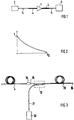
- FIG. 1 shows an optical communication system with an electrical-optical converter 2 on the transmitting side and an optical-electrical converter 3 on the receiving side, which are connected to one another via an optical waveguide 5.
- a message transmission system with an electrical-optical converter on the transmission side and a plurality of distributed optical-electrical converters on the reception side is also possible. However, this is not important for the invention.
- the communication system shown in FIG. 1 also has a fiber optic amplifier 1 and two power limiters 4.
- a power limiter 4 is arranged before and one after the fiber optic amplifier 1, and it is designed as a doped optical waveguide piece.
- the connection of the two power limiters with the fiber optic amplifier 1 and the optical waveguide 5 takes place with the aid of the known splicing technique.
- the power limiter can also be designed differently, e.g. as a plate made of an absorber material, which at an interruption point of the optical waveguide 5, e.g. before and after the optical amplifier.
- This absorber material has properties that will be described later.
- fiber optic amplifiers are also cascaded.
- the power limiters can be arranged so that there is a power limiter in each of the links between the individual fiber optic amplifiers.
- the power limiter has the following properties.
- the performance ratio T P L P 0 is shown as a function of the optical input power P0 of the power limiter.
- P (L) is the optical output power of a power limiter with length L.
- the dependence of the attenuation in the power limiter, as shown in FIG. 2, is preferably non-linear, so that optical radiation with high power is attenuated disproportionately.
- This damping in the power limiter can be done by light scattering and / or absorption.
- a power limiter made of an absorber material in which the absorption is a two-photon absorption is preferably used. This is because it shows the particularly suitable non-linear dependency on the optical input power. This absorption is described, for example, in the book "The Principles of Nonlinear Optics", Y.R. Shen, John Wiley & Sons, pp. 202-210, but not in connection with a specific material and not with optical fibers.
- the specified requirement is fulfilled e.g. a doped optical waveguide piece made of an absorber material with two-photon absorption.
- an absorber material is e.g. Neodymium Nd or Thulium Tm.
- the choice of the doping element and the doping of an optical waveguide ensure that two-photon absorption takes place.
- the damping capacity of the power limiter is determined by the length of the doped fiber section.
- the absorbent material is preferably a semiconductor of type II-VI and in particular cadmium telluride CdTe.
- the power limiter is preferably connected in series with the doped optical waveguide piece 33 by a splice 34.
- the absorbing semiconductor material has a bandgap corresponding to a wavelength between 750 nm and 1550 nm.
- a power limiter must be used if the loss to be induced is 30 dB , which is designed as an optical waveguide, have a length of 30 m. The corresponding loss is then 0.3 dB at a power of 50 mW.
Landscapes
- Physics & Mathematics (AREA)
- Nonlinear Science (AREA)
- General Physics & Mathematics (AREA)
- Optics & Photonics (AREA)
- Lasers (AREA)
- Optical Communication System (AREA)
Claims (8)
- Système de transmission de l'information pour transmettre un signal optique par l'intermédiaire d'un guide d'ondes lumineuses (5), comportant au moins un amplificateur à fibre optique (1), un convertisseur électro-optique (2) du côté d'émission, au moins un convertisseur opto-électrique (3) du côté réception, et un limiteur de puissance (4) qui est installé sur le chemin optique de transmission et dont le coefficient d'absorption croît lorsque la puissance optique d'entrée croît,
caractérisé
par le fait que le limiteur de puissance (4) est un élément de guide d'ondes lumineuses à fibre optique dopé comportant un matériau absorbant dans le cas duquel l'absorption est une absorption à deux photons. - Amplificateur à fibre optique pour un système de transmission de l'information caractérisé par le fait qu'il comporte comme limiteur de puissance (4) un élément de guide d'ondes lumineuses à fibre optique, dopé, qui lui est réuni par construction et dont le coefficient d'absorption croît lorsque la puissance optique d'entrée croît.
- Système de transmission de l'information selon la revendication 1, ou amplificateur optique selon la revendication 2,
caractérisé par le fait que l'élément de guide d'ondes lumineuses est dopé au néodyme Nd. - Système de transmission de l'information selon la revendication 1 ou amplificateur optique selon la revendication 2,
caractérisé par le fait que l'élément de guide d'ondes lumineuses est dopé au thulium Tm. - Système de transmission de l'information selon la revendication 1 ou amplificateur optique selon la revendication 2,
caractérisé par le fait que dans l'élément de guide d'ondes lumineuses, dopé, est réparti un élément absorbant la lumière et semiconducteur, sous forme de microcristallites, dans le cas duquel l'absorption est une absorption à deux photons. - Système de transmission de l'information ou amplificateur optique selon la revendication 4,
caractérisé par le fait que le matériau absorbant est un matériau semiconducteur du type II-VI. - Système de transmission de l'information ou amplificateur optique selon la revendication 5,
caractérisé par le fait que le matériau absorbant est le tellurure de cadmium CdTe. - Système de transmission de l'information ou amplificateur optique selon la revendication 6, caractérisé par le fait que le matériau absorbant la lumière et semiconducteur possède une bande interdite correspondant à une longueur d'onde qui se situe entre 750 nm et 1550 nm.
Applications Claiming Priority (4)
| Application Number | Priority Date | Filing Date | Title |
|---|---|---|---|
| FR9204505 | 1992-04-13 | ||
| FR9204505A FR2689982B1 (fr) | 1992-04-13 | 1992-04-13 | Amplificateur optique a fibre et systeme optique comportant cet amplificateur. |
| DE4229292 | 1992-09-02 | ||
| DE19924229292 DE4229292C2 (de) | 1992-09-02 | 1992-09-02 | Optisches Nachrichtenübertragungssystem mit einem Leistungsbegrenzer für Riesenimpulse |
Publications (2)
| Publication Number | Publication Date |
|---|---|
| EP0565993A1 EP0565993A1 (fr) | 1993-10-20 |
| EP0565993B1 true EP0565993B1 (fr) | 1996-01-10 |
Family
ID=25918155
Family Applications (1)
| Application Number | Title | Priority Date | Filing Date |
|---|---|---|---|
| EP93105651A Expired - Lifetime EP0565993B1 (fr) | 1992-04-13 | 1993-04-06 | Système optique de transmission de données avec un limitateur de puissance des impulsions à haute énergie |
Country Status (6)
| Country | Link |
|---|---|
| EP (1) | EP0565993B1 (fr) |
| JP (1) | JPH06102546A (fr) |
| CA (1) | CA2093724A1 (fr) |
| DE (1) | DE59301374D1 (fr) |
| DK (1) | DK0565993T3 (fr) |
| ES (1) | ES2085067T3 (fr) |
Families Citing this family (7)
| Publication number | Priority date | Publication date | Assignee | Title |
|---|---|---|---|---|
| US5074963A (en) * | 1990-07-27 | 1991-12-24 | The Goodyear Tire & Rubber Company | Furnish composition |
| DE19647488A1 (de) * | 1996-11-16 | 1998-05-20 | Alsthom Cge Alcatel | Optischer Verstärker für Signale einer großen Bandbreite und optisches Übertragungssystem mit einem solchen optischen Verstärker |
| US6134372A (en) * | 1997-10-01 | 2000-10-17 | Sumitomo Osaka Cement Co., Ltd. | Light intensity attenuator and attenuating method |
| GB9814252D0 (en) | 1998-07-02 | 1998-09-02 | Marconi Gec Ltd | Optical power detection |
| US7840098B2 (en) * | 2005-01-20 | 2010-11-23 | Intel Corporation | Variable optical power limiter |
| JP2011002543A (ja) * | 2009-06-17 | 2011-01-06 | Nippon Telegr & Teleph Corp <Ntt> | 光ヒューズ |
| JP5059221B2 (ja) * | 2011-09-13 | 2012-10-24 | 日本電信電話株式会社 | 光リミッタ回路および光受信回路 |
Family Cites Families (3)
| Publication number | Priority date | Publication date | Assignee | Title |
|---|---|---|---|---|
| GB2219126A (en) * | 1988-05-27 | 1989-11-29 | Stc Plc | Laser and optical amplifiers |
| US4846561A (en) * | 1988-06-21 | 1989-07-11 | The United States Of America As Represented By The Secretary Of The Army | Monolithic optical power limiter based on two-photon absorption |
| US4973125A (en) * | 1989-08-25 | 1990-11-27 | National Research Council Of Canada | All optical self limiter for fiber optics |
-
1993
- 1993-04-06 EP EP93105651A patent/EP0565993B1/fr not_active Expired - Lifetime
- 1993-04-06 ES ES93105651T patent/ES2085067T3/es not_active Expired - Lifetime
- 1993-04-06 DK DK93105651.9T patent/DK0565993T3/da active
- 1993-04-06 DE DE59301374T patent/DE59301374D1/de not_active Expired - Fee Related
- 1993-04-08 CA CA002093724A patent/CA2093724A1/fr not_active Abandoned
- 1993-04-13 JP JP5086488A patent/JPH06102546A/ja active Pending
Also Published As
| Publication number | Publication date |
|---|---|
| DE59301374D1 (de) | 1996-02-22 |
| ES2085067T3 (es) | 1996-05-16 |
| CA2093724A1 (fr) | 1993-10-14 |
| JPH06102546A (ja) | 1994-04-15 |
| DK0565993T3 (da) | 1996-02-12 |
| EP0565993A1 (fr) | 1993-10-20 |
Similar Documents
| Publication | Publication Date | Title |
|---|---|---|
| EP0613221B1 (fr) | Amplificateur à fibre optique à étages multiples | |
| EP0569769B1 (fr) | Système de télécommunications optique avec dispositif de surveillance pour éviter de fortes impulsions | |
| DE60116101T2 (de) | Kaskadiertes pumpsystem zur verteilten ramanverstärkung in faseroptischen übertragungssystemen | |
| DE19549868B4 (de) | Optische Impulsverstärkung unter Verwendung chirp-modulierter Bragg-Gitter | |
| EP0233617B1 (fr) | Module d'émission et de réception optique | |
| DE69737117T2 (de) | Unterdrückung von Übersprechen in einem optischen Mehrwegverstärker | |
| DE60109024T2 (de) | Verbesserter breitbandiger Erbium-dotierter Faserverstärker (EDFA) | |
| EP0579023B1 (fr) | Système de transmission d'informations optiques avec filtre optique pour protéger contres les très grandes impulsions | |
| EP1130821A2 (fr) | Amplificateur optique bidirectionnel à faible bruit | |
| EP0502386B1 (fr) | Transducteur opto-électrique à dynamique élargie | |
| EP0565993B1 (fr) | Système optique de transmission de données avec un limitateur de puissance des impulsions à haute énergie | |
| DE3230570A1 (de) | Sende- und empfangseinrichtung fuer ein faseroptisches sensorsystem | |
| DE19702891C2 (de) | Lichtleiterfaserverstärker | |
| DE19521400A1 (de) | Übertragungssystem über eine Lichtleitfaserleitung ohne Signalregenerierung mit Verstärkungen entfernt vom und am Ende | |
| EP0637860B1 (fr) | Amplificateur à fibres optiques avec dispositif de contrÔle de la puissance de pompage et d'entrée | |
| DE60214936T2 (de) | Polarisationserhaltender optischer Faserverstärker | |
| DE10112806C1 (de) | Pumpquelle mit erhöhter Pumpleistung zur optischen breitbandigen Raman-Verstärkung | |
| EP0497140B1 (fr) | Amplificateur optique | |
| EP0618650B1 (fr) | Amplificateur à fibres optiques avec dispositif de contrÔle de la puissance d'entrée | |
| DE4229292C2 (de) | Optisches Nachrichtenübertragungssystem mit einem Leistungsbegrenzer für Riesenimpulse | |
| DE4028180C2 (de) | Anordnung zur Verstärkung eines Solitonensignals mittels stimulierter Raman-Streuung | |
| EP0637107B1 (fr) | Amplificateur à fibre optique utilisé comme convertisseur de longueur d'onde | |
| DE60012826T2 (de) | Multiband-Ramanverstärker | |
| EP0301388B1 (fr) | Emetteur à réflexion pour un système de communication bidirectionnel à fibre optique | |
| DE602004010141T2 (de) | Wellenlängenselektive optische signalverarbeitungseinrichtung |
Legal Events
| Date | Code | Title | Description |
|---|---|---|---|
| PUAI | Public reference made under article 153(3) epc to a published international application that has entered the european phase |
Free format text: ORIGINAL CODE: 0009012 |
|
| AK | Designated contracting states |
Kind code of ref document: A1 Designated state(s): BE CH DE DK ES FR GB IT LI NL SE |
|
| 17P | Request for examination filed |
Effective date: 19931119 |
|
| 17Q | First examination report despatched |
Effective date: 19940808 |
|
| GRAA | (expected) grant |
Free format text: ORIGINAL CODE: 0009210 |
|
| AK | Designated contracting states |
Kind code of ref document: B1 Designated state(s): BE CH DE DK ES FR GB IT LI NL SE |
|
| REG | Reference to a national code |
Ref country code: DK Ref legal event code: T3 |
|
| REF | Corresponds to: |
Ref document number: 59301374 Country of ref document: DE Date of ref document: 19960222 |
|
| RAP2 | Party data changed (patent owner data changed or rights of a patent transferred) |
Owner name: ALCATEL SEL AKTIENGESELLSCHAFT Owner name: ALCATEL N.V. |
|
| REG | Reference to a national code |
Ref country code: CH Ref legal event code: NV Representative=s name: JUERG ULRICH C/O ALCATEL STR AG |
|
| GBT | Gb: translation of ep patent filed (gb section 77(6)(a)/1977) |
Effective date: 19960219 |
|
| ITF | It: translation for a ep patent filed |
Owner name: DOTT. ANTONIO SERGI |
|
| ET | Fr: translation filed | ||
| NLT2 | Nl: modifications (of names), taken from the european patent patent bulletin |
Owner name: ALCATEL N.V. |
|
| REG | Reference to a national code |
Ref country code: ES Ref legal event code: FG2A Ref document number: 2085067 Country of ref document: ES Kind code of ref document: T3 |
|
| PLBE | No opposition filed within time limit |
Free format text: ORIGINAL CODE: 0009261 |
|
| STAA | Information on the status of an ep patent application or granted ep patent |
Free format text: STATUS: NO OPPOSITION FILED WITHIN TIME LIMIT |
|
| 26N | No opposition filed | ||
| PGFP | Annual fee paid to national office [announced via postgrant information from national office to epo] |
Ref country code: GB Payment date: 19980312 Year of fee payment: 6 |
|
| PGFP | Annual fee paid to national office [announced via postgrant information from national office to epo] |
Ref country code: FR Payment date: 19980313 Year of fee payment: 6 |
|
| PGFP | Annual fee paid to national office [announced via postgrant information from national office to epo] |
Ref country code: DE Payment date: 19980318 Year of fee payment: 6 |
|
| PGFP | Annual fee paid to national office [announced via postgrant information from national office to epo] |
Ref country code: DK Payment date: 19980320 Year of fee payment: 6 Ref country code: SE Payment date: 19980320 Year of fee payment: 6 Ref country code: NL Payment date: 19980320 Year of fee payment: 6 |
|
| PGFP | Annual fee paid to national office [announced via postgrant information from national office to epo] |
Ref country code: CH Payment date: 19980325 Year of fee payment: 6 |
|
| PGFP | Annual fee paid to national office [announced via postgrant information from national office to epo] |
Ref country code: BE Payment date: 19980326 Year of fee payment: 6 |
|
| PGFP | Annual fee paid to national office [announced via postgrant information from national office to epo] |
Ref country code: ES Payment date: 19980417 Year of fee payment: 6 |
|
| PG25 | Lapsed in a contracting state [announced via postgrant information from national office to epo] |
Ref country code: GB Free format text: LAPSE BECAUSE OF NON-PAYMENT OF DUE FEES Effective date: 19990406 |
|
| PG25 | Lapsed in a contracting state [announced via postgrant information from national office to epo] |
Ref country code: SE Free format text: LAPSE BECAUSE OF NON-PAYMENT OF DUE FEES Effective date: 19990407 Ref country code: ES Free format text: LAPSE BECAUSE OF NON-PAYMENT OF DUE FEES Effective date: 19990407 |
|
| PG25 | Lapsed in a contracting state [announced via postgrant information from national office to epo] |
Ref country code: LI Free format text: LAPSE BECAUSE OF NON-PAYMENT OF DUE FEES Effective date: 19990430 Ref country code: DK Free format text: LAPSE BECAUSE OF NON-PAYMENT OF DUE FEES Effective date: 19990430 Ref country code: CH Free format text: LAPSE BECAUSE OF NON-PAYMENT OF DUE FEES Effective date: 19990430 Ref country code: BE Free format text: LAPSE BECAUSE OF NON-PAYMENT OF DUE FEES Effective date: 19990430 |
|
| BERE | Be: lapsed |
Owner name: ALCATEL N.V. Effective date: 19990430 |
|
| PG25 | Lapsed in a contracting state [announced via postgrant information from national office to epo] |
Ref country code: NL Free format text: LAPSE BECAUSE OF NON-PAYMENT OF DUE FEES Effective date: 19991101 |
|
| GBPC | Gb: european patent ceased through non-payment of renewal fee |
Effective date: 19990406 |
|
| REG | Reference to a national code |
Ref country code: CH Ref legal event code: PL |
|
| PG25 | Lapsed in a contracting state [announced via postgrant information from national office to epo] |
Ref country code: FR Free format text: LAPSE BECAUSE OF NON-PAYMENT OF DUE FEES Effective date: 19991231 |
|
| NLV4 | Nl: lapsed or anulled due to non-payment of the annual fee |
Effective date: 19991101 |
|
| EUG | Se: european patent has lapsed |
Ref document number: 93105651.9 |
|
| REG | Reference to a national code |
Ref country code: FR Ref legal event code: ST |
|
| PG25 | Lapsed in a contracting state [announced via postgrant information from national office to epo] |
Ref country code: DE Free format text: LAPSE BECAUSE OF NON-PAYMENT OF DUE FEES Effective date: 20000201 |
|
| REG | Reference to a national code |
Ref country code: DK Ref legal event code: EBP |
|
| REG | Reference to a national code |
Ref country code: ES Ref legal event code: FD2A Effective date: 20010503 |
|
| PG25 | Lapsed in a contracting state [announced via postgrant information from national office to epo] |
Ref country code: IT Free format text: LAPSE BECAUSE OF NON-PAYMENT OF DUE FEES;WARNING: LAPSES OF ITALIAN PATENTS WITH EFFECTIVE DATE BEFORE 2007 MAY HAVE OCCURRED AT ANY TIME BEFORE 2007. THE CORRECT EFFECTIVE DATE MAY BE DIFFERENT FROM THE ONE RECORDED. Effective date: 20050406 |