EP0565005A1 - Tube à rayon X à anode tournante - Google Patents
Tube à rayon X à anode tournante Download PDFInfo
- Publication number
- EP0565005A1 EP0565005A1 EP93105533A EP93105533A EP0565005A1 EP 0565005 A1 EP0565005 A1 EP 0565005A1 EP 93105533 A EP93105533 A EP 93105533A EP 93105533 A EP93105533 A EP 93105533A EP 0565005 A1 EP0565005 A1 EP 0565005A1
- Authority
- EP
- European Patent Office
- Prior art keywords
- iron
- alloy
- rotating member
- whose main
- rotating
- Prior art date
- Legal status (The legal status is an assumption and is not a legal conclusion. Google has not performed a legal analysis and makes no representation as to the accuracy of the status listed.)
- Granted
Links
Images


Classifications
-
- H—ELECTRICITY
- H01—ELECTRIC ELEMENTS
- H01J—ELECTRIC DISCHARGE TUBES OR DISCHARGE LAMPS
- H01J31/00—Cathode ray tubes; Electron beam tubes
- H01J31/08—Cathode ray tubes; Electron beam tubes having a screen on or from which an image or pattern is formed, picked up, converted, or stored
- H01J31/10—Image or pattern display tubes, i.e. having electrical input and optical output; Flying-spot tubes for scanning purposes
- H01J31/12—Image or pattern display tubes, i.e. having electrical input and optical output; Flying-spot tubes for scanning purposes with luminescent screen
- H01J31/15—Image or pattern display tubes, i.e. having electrical input and optical output; Flying-spot tubes for scanning purposes with luminescent screen with ray or beam selectively directed to luminescent anode segments
-
- H—ELECTRICITY
- H01—ELECTRIC ELEMENTS
- H01J—ELECTRIC DISCHARGE TUBES OR DISCHARGE LAMPS
- H01J35/00—X-ray tubes
- H01J35/02—Details
- H01J35/04—Electrodes ; Mutual position thereof; Constructional adaptations therefor
- H01J35/08—Anodes; Anti cathodes
- H01J35/10—Rotary anodes; Arrangements for rotating anodes; Cooling rotary anodes
- H01J35/101—Arrangements for rotating anodes, e.g. supporting means, means for greasing, means for sealing the axle or means for shielding or protecting the driving
- H01J35/1017—Bearings for rotating anodes
- H01J35/104—Fluid bearings
-
- H—ELECTRICITY
- H01—ELECTRIC ELEMENTS
- H01J—ELECTRIC DISCHARGE TUBES OR DISCHARGE LAMPS
- H01J2235/00—X-ray tubes
- H01J2235/10—Drive means for anode (target) substrate
- H01J2235/1046—Bearings and bearing contact surfaces
- H01J2235/106—Dynamic pressure bearings, e.g. helical groove type
-
- H—ELECTRICITY
- H01—ELECTRIC ELEMENTS
- H01J—ELECTRIC DISCHARGE TUBES OR DISCHARGE LAMPS
- H01J2235/00—X-ray tubes
- H01J2235/16—Vessels
- H01J2235/165—Shielding arrangements
- H01J2235/167—Shielding arrangements against thermal (heat) energy
Definitions
- the present invention relates to an X-ray tube of the rotary anode type and, more particularly, an improvement of the rotating mechanism for supporting the anode target.
- a disk-like anode target is fixed to a rotary structure which is rotatably supported by a stationary structure and bearings are formed between the stationary and rotary structure.
- An electron beam is bombarded on the anode target so that X-rays are radiated from the anode target, while exciting electromagnetic coils located outside a vacuum envelope to rotate the rotary structure at high speed.
- Ball bearings have been used for a long time but it is now expected that bearings of the hydro-dynamic pressure type will become used.
- the rotary structure by which the anode target is supported usually includes an outer cylinder made of copper, high in electric conductivity, to serve as a rotor, and a target support welded integral to the rotor is soldered.
- Rotating magnetic field is applied from a stator located outside the vacuum envelope to the rotor to rotate the rotor at high speed according to the principle of the induction motor.
- noises become larger as the temperature of the ball bearings rises higher. This is because the clearance between the bearings is changed and because solid lubricant is fatigued.
- Various kinds of measure have been proposed to suppress the temperature rise in the ball bearings. Some of them are disclosed in Japanese Patent Disclosures 55-3180, 55-78449 and 2-144836. However, they have not become practically used yet.
- the X-ray tube in which the hydro-dynamic pressure type bearings are used is characterized in that rotating noises are hardly created.
- the X-ray diagnostic instrument in which the X-ray tube is incorporated is often used in intense coldness or at a temperature lower than 0°C. It is therefore preferable that lubricant is made of materials whose melting points are low. Ga alloys are the most suitable for use as lubricant because their vapor pressures are low and their melting points are equal to or near to 10°C.
- Ga alloys are so active as to react with bearing component members. As the result, the clearance between bearings is gradually changed to deteriorate the rotating characteristics of bearings. This limits those materials, of which the bearings are made, to tungsten (W), molybdenum (Mo), tantalum (Ta), niobium (Ni) and alloys of them, which cannot be corroded by Ga alloys. Copper (Cu), tin, iron (Fe), nickel (Ni) and iron alloy such as stainless steel, however, are low in cost and easy to be processed. But they are regarded as being impractical because they can be quite easily corroded.
- the object of the present invention is therefore to provide an X-ray tube of the rotary anode type wherein bearings of the hydro-dynamic pressure type, although made of such materials as iron alloys low in cost and easy to be processed, cannot be corroded by metal lubricant such as Ga alloy to thereby keep their rotating characteristics more stable for a longer time.
- an X-ray tube of the rotary anode type comprising an anode target; a rotary structure to which the anode target is fixed, including a first rotating member to which the anode target is mechanically connected, the first rotating member being made of one of those materials which have a heat conductivity smaller than 0.1(cal/cm ⁇ sec ⁇ °C) at a temperature range of 0 to 500°C.
- the stationary structure for rotatably supporting the rotary structure; slide bearings formed between the rotary and the stationary structures and including spiral grooves; and a liquid metal lubricant applied to the slide bearings; It is more preferable that the first rotating member is made of material whose heat conductivity is lower than 0.08(cal/cm ⁇ sec ⁇ °C) at a temperature range of 0 to 500°C.
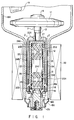
- An embodiment of the present invention shown in Figs. 1 through 4 has the following arrangement.
- a disk-like anode target 11 is connected and fixed integral to a shaft 13, which is made of Mo alloy and which is projected from one end of a cylindrically rotary structure 12, by means of a fixing screw 14.
- a stationary structure 15 is fitted into the cylindrical rotary structure 12 and a disk-like closing member 16 is fixed to the lower end of the rotary structure 12.
- a lower end portion 17 of the stationary structure 15 is connected air-tight to the cylindrical glass section of a vacuum envelope 18 through an auxiliary metal ring 17a and thin seal rings 18b and 18c.
- the vacuum envelope 18 has a large-diameter portion by which the anode target 11 is enclosed, and a window 18a through which X-ray is radiated outside the housing 18.
- a cathode 19 is arranged in opposite to the anode target 11.
- Radial and thrust slide bearings 20a and 20b of the hydro-dynamic pressure type which are disclosed in the above-mentioned references are arranged between the cylindrical rotary structure 12 and the stationary structure 15 fitted in the structure 12.
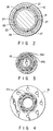
- Each of the two radial slide bearings 20a which are arranged along the rotating axis and which are separated from each other has two herringbone spiral pattern grooves 21a formed on an outer circumference 15a of the stationary structure 15.
- One of the two thrust slide bearings 20b has circle-like herringbone spiral pattern grooves 21b formed on an end face 15b of the stationary structure 15 as shown in Fig. 3.
- the other has circle-like herringbone spiral pattern grooves 21c shown in Fig. 4 and formed on the top of a disk-like flange 16 with which the end face of the stationary structure 15 is contacted.
- Each of those slide bearing faces of the rotary structure may be made flat or provided with spiral grooves if necessary.
- both of these rotary and stationary structures are kept to have a clearance of 20 ⁇ m between their bearing faces and liquid metal lubricant (not shown) of a gallium alloy such as Ga, GaIn and Ga-In-Sn alloy is supplied into these gas or clearances and spiral grooves.
- a bismuth alloy such as Bi-In-Pb-Sn, In-Bi and In-Bi-Sn alloy may be used as the metal lubricant.
- Stators 3 each having an electromagnetic coil are located symmetrical to each other and in opposite to the rotary structure 12 with the vacuum envelope 18 interposed between them. Rotating magnetic field is thus generated by these stators 3 to cause the anode target 11 to be rotated at high speed and in a direction shown by an arrow P. Electron beam emitted from the cathode 19 is bombarded on the anode target 11 to irradiate X-ray. Heat thus produced in the target 11 is radiated but a part of it is transmitted to the bearings 20a and 20b through the shaft 13 and the rotary structure 12.
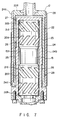
- the rotary structure 12 includes a first rotating member or intermediate cylinder 22 connected integral to the anode target 11 through the shaft 13, a second rotating member or inner bottom-provided cylinder 23 fitted into the first rotating cylinder 22 with a heat insulating clearance interposed between them, and an outer cylinder 24 made of copper and fitted onto the intermediate cylinder 22.
- the inner bottom-provided cylinder 23 cooperates with the outer circumference of the stationary structure 15 at some parts of its inner face to form the slide bearing faces.
- the width of the heat-insulating clearance 26 is in a range of 0.1 to 1 mm in the radial direction or 0.5 mm, for example.
- the inner cylinder 23 whose inner face serves as the slide bearing face of the dynamic pressure type is made of pure iron, iron alloy tool steel such as stainless steel and SKD-11 (JIS) and nickel, which are low in cost, good in process-ability, comparatively high in strength and made well wet by Ga alloy lubricant.
- the inner cylinder 23 is provided with four small projections 27 projected from the upper outer circumference thereof and these four projections 27 enable the inner cylinder 23 to be contacted with the inner face of the intermediate cylinder 22 at a small contact area and both of the inner and intermediate cylinders 23 and 22 to be kept at a correct axial position while keeping the heat-insulating clearance 26 between them.
- the intermediate cylinder 22 is made of such material that has a thermal conductivity sufficiently smaller than that of pure iron, smaller than 0.1(cal/cm ⁇ sec ⁇ °C), preferably smaller than 0.08(cal/cm ⁇ sec ⁇ °C) at a temperature range of 0 to 500°C. It is fixed to the shaft 13 at its upper end and partly connected to the inner cylinder 23 at its lower end by soldering parts 25 which are located adjacent to the radial slide bearings 20a remote from the anode target 11.
- the intermediate and inner cylinders 22 and 23 are connected integral to each other at the position remote from the anode target 11 but kept separated from each other at their other remaining portions by the heat insulating clearance or area 26.
- the intermediate and inner cylinders 22 and 23 When the efficiency of applying rotating magnetic field to the intermediate and inner cylinders 22 and 23 is considered, it is preferable that at least one of these cylinders is made of ferromagnetic material.
- the other cylinder 24 is made of copper or copper alloy which has a specific electric resistance smaller than 6 ⁇ 10 ⁇ 8 ( ⁇ cm) at a temperature of 20°C.
- the intermediate and outer cylinders 22 and 24 may be arranged coaxial, having a heat insulating clearance of 0.5 mm or less between them, but not between those portions which are connected to each other by soldering parts 25. When arranged in this manner, temperature rise in their bearing sections can be further reduced.
- those faces 22a and 24a of the intermediate and outer cylinders 22 and 24 which are opposed to the anode target 11 are made into mirror surfaces. Heat radiated from the anode target 11 can be thus reflected by these mirror faces 22a and 24a to thereby suppress the temperature rise in the bearing sections. Still further, that outer circumference of the outer cylinder 24, except the mirror face 24a, is coated by a black coating 24b, by which heat reached the outer cylinder 24 can be dispersed by radiation to thereby further suppress the temperature rise in the bearing sections.
- the inner cylinder 23 whose inner face serves as the bearing one is made of preferably one of the following materials which can be easily processed and which have a heat conductivity substantially equal to or near that of the intermediate cylinder 22.
- Alloy whose main components are iron and nickel; alloy whose main components are iron, nickel and cobalt; alloy whose main components are iron and chromium, said iron including therein various kinds of stainless steel, and alloy whose main components are iron, chromium and nickel; and iron alloy including iron, chromium and at least one of carbon, vanadium, molybdenum, and tungsten, said iron including therein tool steel.
- the stationary structure 15 is made of preferably one of the above-mentioned materials of which the inner cylinder 23 is made, but it may be made of W, Ta, Nb, or alloy whose main component is at least one of these materials, or ceramics which can be made wet by Ga alloy.
- the intermediate cylinder 22 is made of one of the following materials which have a heat conductivity smaller than 0.1(cal/cm ⁇ sec°C) at a temperature range of 0 to 500°C.
- Alloy whose main components are iron and nickel; alloy whose main components are iron, nickel and cobalt; alloy whose main components are iron and chromium, said iron including therein various kinds of stainless steel, and alloy whose main components are iron, chromium and nickel; iron alloy including iron, chromium and at least one of carbon, vanadium, molybdenum and tungsten, said iron including therein tool steel; and ceramics which can be made wet by Ga alloy.
- Heat conductivities and temperatures resultant in a bearing section B in the case of our examples which are made of the above-mentioned materials are shown in Table 1 for comparison.
- Ceramics whose electric resistance is high it is needed that conductive film is coated on a part of the surface of the ceramics to form a path through which anode current flows.
- Temperatures resultant in the bearing section B represent those highest values which could be calculated when electron beam input of 240W was continuously applied to the anode target in the case of our examples which are same in structure and dimension.
- Comparison examples which were made of pure iron and nickel are also shown in Table 1.
- the temperature resultant in the bearing section when the X-ray tube of the rotary anode type whose bearing members are made of the materials used for our examples in Table 1 is under operation can be suppressed lower than about 200°C. Even when the bearing members are made of the above-mentioned iron alloys, therefore, their bearing faces are hardly corroded to thereby enable their dynamic pressure type slide bearings to be more stably used for a longer time.
- the lower end of the intermediate cylinder 22 is connected to the lower end portion of the inner cylinder 23 at such position that is adjacent to the radial slide bearing 20a remote from the anode target 11. Most of the other portion thereof cooperates with the inner cylinder 23 to form the heat insulating clearance 26.
- the heat insulating clearance 26 is formed between the intermediate and inner cylinders 22 and 23 at such an area that is nearer to the target when viewed from a center point T of the rotating axis between two radial slide bearings 20a and along the heat transmitting line, but the other portions of these cylinders which are remoter from the target are closely contacted with each other.
- a ring-shaped recess 15c is formed round the center portion of the stationary structure 15.
- the inner cylinder 23 is welded to the intermediate cylinder 22 at a position which corresponds to the center recess 15c of the stationary structure 15.
- This welded portion between the intermediate and inner cylinders 22 and 23 is denoted by reference numeral 25.
- the heat insulating clearances 26 are formed between the intermediate and inner cylinders 22 and 23 but on both sides of the welded portion when viewed in the rotating axis direction.
- Upper end portions of the intermediate and outer cylinders 22 and 24 which are nearer to the anode target are connected to each other by soldering parts 28, while their lower end portions 24c are mechanically fitted to each other by wave-shaped concaves and convexes which are formed on inner and outer faces thereof in the circumferential direction. Stress concentration on the soldering parts 28 caused by rotating drive force transmitted from the outer cylinder to the intermediate one can be thus reduced.
- the column-like rotary structure 12 connected integral to and rotated together with the anode target 11 is housed in the cylinder-shaped stationary structure 15.
- the stationary structure 15 has in the top thereof a through-hole through which the rotating shaft 13 is passed, and a disk-like closing member 16 and a anode support 17 are fixed to the open bottom of the stationary structure 15 by plural screws.
- the closing member 16 is contacted with the lower end face of the rotary structure 12 and provided with a spiral groove 21c on its contacted face.
- a ferromagnetic cylinder 31 which serves is the rotor of a motor is arranged round the stationary structure 15 and the outer cylinder 24 made of copper is arranged round the cylinder 31.
- the top of the cylinder 31 is mechanically and strongly fixed to the rotating shaft 13.
- the rotary structure 12 includes a first column-like rotating member 33 to which the rotating shaft 13 for supporting the anode target 11 is fixed, and a second cylinder-like rotating member 34 coaxially fitted onto the first rotating member 33 and serving to form the slide bearing face.
- These first and second rotating members 33 and 34 are connected integral to each other by soldering parts 25 at their lower end portions which are located remoter from the anode target when viewed in the axial direction and along the heat transmitting line.
- the heat insulating clearance 26 is formed between the first and second rotating members 33 and 34 except those portions thereof which are connected to each other by the soldering parts 25.
- Four projections 27 are projected from the upper end portion of the first rotating member 33 and contacted with the inner face of the second rotating member 34. They can be thus stably kept coaxial.
- the outer circumference and the top of the second rotating member 34 form bearing faces of the dynamic pressure type bearings 20a and 20b and herringbone pattern spiral grooves are formed on them.
- the heat transmitting line extending from the anode target to the bearings can have a larger heat resistance due to the heat insulating clearance 26.
- the heat insulating areas 26 and 29 may not be spacial clearances. Ceramics whose heat conductivity is quite small, and other heat insulating materials may be used instead.
- temperature rises in the bearing component members and in Ga alloy lubricant supplied to them can be more reliably reduced when the X-ray tube is under operation.
- the bearing component members can be hardly corroded by Ga alloy.
- An X-ray tube of the rotary anode type lower in cost and capable of keeping its bearing characteristics more stable for a longer time, can be thus provided.
Landscapes
- Sliding-Contact Bearings (AREA)
- Apparatus For Radiation Diagnosis (AREA)
- X-Ray Techniques (AREA)
Applications Claiming Priority (4)
| Application Number | Priority Date | Filing Date | Title |
|---|---|---|---|
| JP11427692 | 1992-04-08 | ||
| JP114276/92 | 1992-04-08 | ||
| JP29624292 | 1992-11-06 | ||
| JP296242/92 | 1992-11-06 |
Publications (2)
| Publication Number | Publication Date |
|---|---|
| EP0565005A1 true EP0565005A1 (fr) | 1993-10-13 |
| EP0565005B1 EP0565005B1 (fr) | 1996-12-11 |
Family
ID=26453061
Family Applications (1)
| Application Number | Title | Priority Date | Filing Date |
|---|---|---|---|
| EP93105533A Expired - Lifetime EP0565005B1 (fr) | 1992-04-08 | 1993-04-02 | Tube à rayon X à anode tournante |
Country Status (6)
| Country | Link |
|---|---|
| US (1) | US5384818A (fr) |
| EP (1) | EP0565005B1 (fr) |
| KR (1) | KR970002680B1 (fr) |
| CN (1) | CN1036961C (fr) |
| CA (1) | CA2093256C (fr) |
| DE (1) | DE69306454T2 (fr) |
Cited By (3)
| Publication number | Priority date | Publication date | Assignee | Title |
|---|---|---|---|---|
| EP1168414A2 (fr) * | 2000-06-15 | 2002-01-02 | Kabushiki Kaisha Toshiba | Tube radiogène à anode tournante et dispositif de tube à rayons X équipé d'un tel tube |
| FR2817393A1 (fr) * | 2000-11-24 | 2002-05-31 | Ge Med Sys Global Tech Co Llc | Element rotatif destine a etre utilise dans un assemblage rotatif d'anode a rayons x, source de rayons x et systeme d'imagerie |
| WO2003043389A2 (fr) * | 2001-11-14 | 2003-05-22 | Koninklijke Philips Electronics, N.V. | Barriere thermique de tube a rayons x |
Families Citing this family (16)
| Publication number | Priority date | Publication date | Assignee | Title |
|---|---|---|---|---|
| JP3839528B2 (ja) * | 1996-09-27 | 2006-11-01 | 浜松ホトニクス株式会社 | X線発生装置 |
| US6212753B1 (en) * | 1997-11-25 | 2001-04-10 | General Electric Company | Complaint joint for interfacing dissimilar metals in X-ray tubes |
| US6256375B1 (en) * | 1999-03-29 | 2001-07-03 | General Electric Company | Target angle matching cathode structure for an X-ray tube |
| US6385293B1 (en) | 2000-02-10 | 2002-05-07 | Philips Medical Systems (Cleveland), Inc. | Thermally equalized X-ray tube bearing |
| US6445770B1 (en) * | 2000-02-10 | 2002-09-03 | Koninklijke Philips Electronics N.V. | Thermally isolated x-ray tube bearing |
| US6456693B1 (en) * | 2001-04-12 | 2002-09-24 | Ge Medical Systems Global Technology Company, Llc | Multiple row spiral groove bearing for X-ray tube |
| US7127035B2 (en) * | 2001-08-29 | 2006-10-24 | Kabushiki Kaisha Toshiba | Rotary anode type X-ray tube |
| DE102004002200B4 (de) * | 2004-01-15 | 2011-05-05 | Siemens Ag | Röntgenröhre |
| US20050162122A1 (en) * | 2004-01-22 | 2005-07-28 | Dunn Glenn M. | Fuel cell power and management system, and technique for controlling and/or operating same |
| CN104051207B (zh) * | 2007-08-16 | 2017-05-24 | 皇家飞利浦电子股份有限公司 | 用于旋转阳极型高功率x射线管构造的阳极盘结构的混合设计 |
| US8774367B2 (en) | 2008-10-22 | 2014-07-08 | Koninklijke Philips N.V. | Bearing within an X-ray tube |
| US8363787B2 (en) * | 2009-03-25 | 2013-01-29 | General Electric Company | Interface for liquid metal bearing and method of making same |
| US7933382B2 (en) | 2009-03-25 | 2011-04-26 | General Electric Company | Interface for liquid metal bearing and method of making same |
| US9500226B2 (en) | 2014-08-13 | 2016-11-22 | General Electric Company | Method and systems for texturing liquid bearing surfaces in X-ray tubes |
| US9972472B2 (en) * | 2014-11-10 | 2018-05-15 | General Electric Company | Welded spiral groove bearing assembly |
| KR101957246B1 (ko) * | 2015-01-27 | 2019-06-27 | 캐논 덴시칸 디바이스 가부시키가이샤 | 회전 양극형 x선관 |
Citations (5)
| Publication number | Priority date | Publication date | Assignee | Title |
|---|---|---|---|---|
| FR2517880A1 (fr) * | 1981-12-09 | 1983-06-10 | Hitachi Ltd | Tube a rayons x a anode rotative |
| EP0477868A1 (fr) * | 1990-09-28 | 1992-04-01 | Koyo Seiko Co., Ltd. | Palier à pression dynamique pour tube à rayons X ayant une anode rotative |
| CA2052473A1 (fr) * | 1990-10-01 | 1992-04-02 | Hidero Anno | Tube a rayons x a anode tournante avec surface de frottement en ceramique |
| CA2052474A1 (fr) * | 1990-10-05 | 1992-04-06 | Katsuhiro Ono | Tube a rayons x a anode tournante |
| EP0496945A1 (fr) * | 1991-01-31 | 1992-08-05 | Kabushiki Kaisha Toshiba | Tube à rayons x du type à anode rotative |
Family Cites Families (6)
| Publication number | Priority date | Publication date | Assignee | Title |
|---|---|---|---|---|
| NL7713634A (nl) * | 1977-12-09 | 1979-06-12 | Philips Nv | Roentgenbuis met draaianode. |
| JPS5578449A (en) * | 1978-12-08 | 1980-06-13 | Toshiba Corp | Rotary anode x-ray tube |
| CN1007851B (zh) * | 1985-04-01 | 1990-05-02 | N·V·菲利蒲光灯制造公司 | 带有螺线槽轴承的x-射线管 |
| JPH02144836A (ja) * | 1988-11-28 | 1990-06-04 | Toshiba Corp | 回転陽極x線管 |
| DE4019614A1 (de) * | 1990-06-20 | 1992-01-02 | Philips Patentverwaltung | Drehanodenroentgenroehre |
| KR960005752B1 (ko) * | 1991-12-10 | 1996-05-01 | 가부시키가이샤 도시바 | X선 장치 |
-
1993
- 1993-04-02 EP EP93105533A patent/EP0565005B1/fr not_active Expired - Lifetime
- 1993-04-02 CA CA002093256A patent/CA2093256C/fr not_active Expired - Fee Related
- 1993-04-02 DE DE69306454T patent/DE69306454T2/de not_active Expired - Fee Related
- 1993-04-08 CN CN93104089A patent/CN1036961C/zh not_active Expired - Fee Related
- 1993-04-08 KR KR1019930005845A patent/KR970002680B1/ko not_active IP Right Cessation
- 1993-04-08 US US08/044,174 patent/US5384818A/en not_active Expired - Lifetime
Patent Citations (5)
| Publication number | Priority date | Publication date | Assignee | Title |
|---|---|---|---|---|
| FR2517880A1 (fr) * | 1981-12-09 | 1983-06-10 | Hitachi Ltd | Tube a rayons x a anode rotative |
| EP0477868A1 (fr) * | 1990-09-28 | 1992-04-01 | Koyo Seiko Co., Ltd. | Palier à pression dynamique pour tube à rayons X ayant une anode rotative |
| CA2052473A1 (fr) * | 1990-10-01 | 1992-04-02 | Hidero Anno | Tube a rayons x a anode tournante avec surface de frottement en ceramique |
| CA2052474A1 (fr) * | 1990-10-05 | 1992-04-06 | Katsuhiro Ono | Tube a rayons x a anode tournante |
| EP0496945A1 (fr) * | 1991-01-31 | 1992-08-05 | Kabushiki Kaisha Toshiba | Tube à rayons x du type à anode rotative |
Cited By (6)
| Publication number | Priority date | Publication date | Assignee | Title |
|---|---|---|---|---|
| EP1168414A2 (fr) * | 2000-06-15 | 2002-01-02 | Kabushiki Kaisha Toshiba | Tube radiogène à anode tournante et dispositif de tube à rayons X équipé d'un tel tube |
| EP1168414A3 (fr) * | 2000-06-15 | 2006-02-15 | Kabushiki Kaisha Toshiba | Tube radiogène à anode tournante et dispositif de tube à rayons X équipé d'un tel tube |
| FR2817393A1 (fr) * | 2000-11-24 | 2002-05-31 | Ge Med Sys Global Tech Co Llc | Element rotatif destine a etre utilise dans un assemblage rotatif d'anode a rayons x, source de rayons x et systeme d'imagerie |
| WO2003043389A2 (fr) * | 2001-11-14 | 2003-05-22 | Koninklijke Philips Electronics, N.V. | Barriere thermique de tube a rayons x |
| WO2003043389A3 (fr) * | 2001-11-14 | 2003-09-12 | Koninkl Philips Electronics Nv | Barriere thermique de tube a rayons x |
| US6707882B2 (en) | 2001-11-14 | 2004-03-16 | Koninklijke Philips Electronics, N.V. | X-ray tube heat barrier |
Also Published As
| Publication number | Publication date |
|---|---|
| KR930022452A (ko) | 1993-11-24 |
| DE69306454D1 (de) | 1997-01-23 |
| CA2093256C (fr) | 1999-06-01 |
| CN1079843A (zh) | 1993-12-22 |
| US5384818A (en) | 1995-01-24 |
| EP0565005B1 (fr) | 1996-12-11 |
| DE69306454T2 (de) | 1997-05-15 |
| CN1036961C (zh) | 1998-01-07 |
| KR970002680B1 (ko) | 1997-03-08 |
| CA2093256A1 (fr) | 1993-10-09 |
Similar Documents
| Publication | Publication Date | Title |
|---|---|---|
| US5384818A (en) | X-ray tube of the rotary anode type | |
| EP0496945A1 (fr) | Tube à rayons x du type à anode rotative | |
| US5204890A (en) | Rotary anode type x-ray tube | |
| US4097759A (en) | X-ray tube | |
| EP2099055A1 (fr) | Tube à rayons x à anode rotative | |
| EP0482386B1 (fr) | Tube à rayons X avec anode tournante | |
| US6480571B1 (en) | Drive assembly for an x-ray tube having a rotating anode | |
| US4644577A (en) | X-ray tube comprising an anode disc rotatably journalled on a helical-groove bearing | |
| JPS6155732B2 (fr) | ||
| US5308172A (en) | Bearing assembly | |
| US5838762A (en) | Rotating anode for x-ray tube using interference fit | |
| US6385293B1 (en) | Thermally equalized X-ray tube bearing | |
| JP3139873B2 (ja) | 回転陽極型x線管 | |
| JP2005520300A (ja) | X線ターゲット用液体金属ヒートパイプ構造 | |
| US20130051533A1 (en) | Liquid metal containment in an x-ray tube | |
| US5303280A (en) | Large diameter anode X-ray tube with reinforced support | |
| US2121632A (en) | X-ray tube | |
| US6157702A (en) | X-ray tube targets with reduced heat transfer | |
| US6512816B1 (en) | Temperature clock for x-ray tubes | |
| JP2011233364A (ja) | 回転陽極型x線管及び回転陽極型x線管装置 | |
| JP3045906B2 (ja) | 回転陽極型x線管 | |
| JP2982915B2 (ja) | 回転陽極x線管 | |
| JP2930280B2 (ja) | 回転陽極型x線管 | |
| JP3410808B2 (ja) | 回転陽極型x線管 | |
| JPS61151956A (ja) | 回転陽極型x線管 |
Legal Events
| Date | Code | Title | Description |
|---|---|---|---|
| PUAI | Public reference made under article 153(3) epc to a published international application that has entered the european phase |
Free format text: ORIGINAL CODE: 0009012 |
|
| 17P | Request for examination filed |
Effective date: 19930429 |
|
| AK | Designated contracting states |
Kind code of ref document: A1 Designated state(s): DE FR GB |
|
| 17Q | First examination report despatched |
Effective date: 19950103 |
|
| GRAG | Despatch of communication of intention to grant |
Free format text: ORIGINAL CODE: EPIDOS AGRA |
|
| GRAH | Despatch of communication of intention to grant a patent |
Free format text: ORIGINAL CODE: EPIDOS IGRA |
|
| GRAH | Despatch of communication of intention to grant a patent |
Free format text: ORIGINAL CODE: EPIDOS IGRA |
|
| GRAA | (expected) grant |
Free format text: ORIGINAL CODE: 0009210 |
|
| AK | Designated contracting states |
Kind code of ref document: B1 Designated state(s): DE FR GB |
|
| REF | Corresponds to: |
Ref document number: 69306454 Country of ref document: DE Date of ref document: 19970123 |
|
| ET | Fr: translation filed | ||
| PLBE | No opposition filed within time limit |
Free format text: ORIGINAL CODE: 0009261 |
|
| STAA | Information on the status of an ep patent application or granted ep patent |
Free format text: STATUS: NO OPPOSITION FILED WITHIN TIME LIMIT |
|
| 26N | No opposition filed | ||
| REG | Reference to a national code |
Ref country code: GB Ref legal event code: 746 Effective date: 19981010 |
|
| REG | Reference to a national code |
Ref country code: FR Ref legal event code: D6 |
|
| REG | Reference to a national code |
Ref country code: GB Ref legal event code: IF02 |
|
| PGFP | Annual fee paid to national office [announced via postgrant information from national office to epo] |
Ref country code: GB Payment date: 20030402 Year of fee payment: 11 |
|
| PG25 | Lapsed in a contracting state [announced via postgrant information from national office to epo] |
Ref country code: GB Free format text: LAPSE BECAUSE OF NON-PAYMENT OF DUE FEES Effective date: 20040402 |
|
| GBPC | Gb: european patent ceased through non-payment of renewal fee | ||
| PGFP | Annual fee paid to national office [announced via postgrant information from national office to epo] |
Ref country code: FR Payment date: 20080312 Year of fee payment: 16 Ref country code: DE Payment date: 20080411 Year of fee payment: 16 |
|
| REG | Reference to a national code |
Ref country code: FR Ref legal event code: ST Effective date: 20091231 |
|
| PG25 | Lapsed in a contracting state [announced via postgrant information from national office to epo] |
Ref country code: DE Free format text: LAPSE BECAUSE OF NON-PAYMENT OF DUE FEES Effective date: 20091103 |
|
| PG25 | Lapsed in a contracting state [announced via postgrant information from national office to epo] |
Ref country code: FR Free format text: LAPSE BECAUSE OF NON-PAYMENT OF DUE FEES Effective date: 20091222 |