EP0564489B1 - Method and apparatus for equalizing the temperature profile of glass sheets in a roller-equipped furnace included in a horizontal tempering plant - Google Patents
Method and apparatus for equalizing the temperature profile of glass sheets in a roller-equipped furnace included in a horizontal tempering plant Download PDFInfo
- Publication number
- EP0564489B1 EP0564489B1 EP92900936A EP92900936A EP0564489B1 EP 0564489 B1 EP0564489 B1 EP 0564489B1 EP 92900936 A EP92900936 A EP 92900936A EP 92900936 A EP92900936 A EP 92900936A EP 0564489 B1 EP0564489 B1 EP 0564489B1
- Authority
- EP
- European Patent Office
- Prior art keywords
- furnace
- blasting
- glass
- glass sheet
- rollers
- Prior art date
- Legal status (The legal status is an assumption and is not a legal conclusion. Google has not performed a legal analysis and makes no representation as to the accuracy of the status listed.)
- Expired - Lifetime
Links
Images
Classifications
-
- C—CHEMISTRY; METALLURGY
- C03—GLASS; MINERAL OR SLAG WOOL
- C03B—MANUFACTURE, SHAPING, OR SUPPLEMENTARY PROCESSES
- C03B29/00—Reheating glass products for softening or fusing their surfaces; Fire-polishing; Fusing of margins
- C03B29/04—Reheating glass products for softening or fusing their surfaces; Fire-polishing; Fusing of margins in a continuous way
- C03B29/06—Reheating glass products for softening or fusing their surfaces; Fire-polishing; Fusing of margins in a continuous way with horizontal displacement of the products
- C03B29/08—Glass sheets
Definitions
- the present invention relates to a method for equalizing the temperature profile of glass sheets in a roller-equipped furnace included in a horizontal tempering plant, wherein the glass sheets are carried on a horizontal level by means of a conveyor consisting of horizontal rollers through a furnace, the opposite surfaces of a glass sheet being exposed to a conduction, convection and radiation heat effect caused by resistance elements, rollers or the like furnace components fitted above and below a glass sheet whereby, in order to equalize the total heat effect applied to the upper and lower surfaces of a glass sheet, the upper surface of a glass sheet is exposed at least in the early stage of a heating cycle to an intensified convection heat effect by blasting air into the furnace near the upper surface of a glass sheet as narrow jets which, through the injector action, create a turbulent flow of the hot air contained in the furnace along the upper surface of a glass sheet.
- the invention relates also to an apparatus for equalizing the temperature profile of glass sheets in a roller-equipped furnace included in a horizontal tempering plant, said apparatus comprising a furnace, heating resistances thereinside for maintaining the furnace temperature close to a glass softening temperature, horizontal rollers inside the furnace for supporting a horizontal glass sheet and providing a conveyor therefor, as well as a blasting manifold above a bearing surface consisting of the rollers for blasting heat-equalizing air into the furnace.
- the convection blasting has been developed further in a manner thatthe air to be blasted is pre-heated in the proximity of rollers below the glass by passing ablasting-air supply pipe through a space below the glass.
- This method is disclosed in more detail in the Applicant's Patent application FI 894191.
- This prior method involves a principle of picking up the pre-heating heat from rollers and from air below the glass. This method was capable of increasing the power of convection blasting while decreasing the amount of air to be blasted.
- a common aspect to all above problems is that it must be possible to focus the convection blasting on a right sport at a right time. It is also essential that the convection effect be as effective as possible with as small amount of air as possible since the ample use of blasting air creates further problems.
- the discharging air produces an extra heat load on undesired spots, leading to problems in terms of sealing and bearing systems.
- the air to be blasted must be heated to the temperature of the furnace air, which requires heating effect.
- the ample use of air colder than the furnace air may also produce problematic, hard-to-control flows in the furnace.
- each blasting pipe is fitted outside a furnace with an ON/OFF-closing valve that can be operated in a programmed or manual way.
- the valves open and close according to the movement of glass in a manner that, when the glass lies within the range of action of a certain pipe, the valve is open. Accordingly, when there is no glass in register with the pipe, the valve is closed. Thus, it is possible to minimize the undesired heating of certain rollers.
- a method and apparatus of the invention can also be utilized during the unloaded period of a furnace e.g. in a manner that, when the rollers at the loading end of a furnace can be expected to be cooled more than the other rollers, the blasting pipes of this particular section are used to blast pre-heated air to the rollers for a certain period of time. This is to avoid the problem that, under a long-term continuous loading, the breakage of glass begins to increase due to the fact that the rollers at the loading end cool more rapidly than the other rollers.
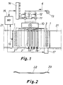
- Pipes 3 are disposed transversely to the advancing direction of glass, i.e. in the same direction as rollers 2.
- Each transverse compressed-air pipe 3 is provided with holes having diameter of circa 1 mm disposed horizontally or slightly downwards and directed in both directions, the distance therebetween being appr. 100 mm.
- the blasting pressure in pipes 3 is appr. 3 - 5 bars.
- the narrow air jets discharging from the holes of pipes 3 create a turbulent flow of hot air contained in the furnace along the upper surface of a glass sheet. This in turn intensifies the transfer of heat through convection heat effect to the upper surface of glass.
- the air is first delivered e.g. through an electrically heated pre-heater 10.
- the air is delivered into a distributing pipe 5, extending longitudinally of the furnace and provided with a plurality of tubes 6, extending transversely of the furnace and positioned below a bearing surface consisting of rollers 2, at every other space between rollers, or e.g. above resistances 8.
- the air advances into a manifold 7 provided with blasting pipes 3.
- the air is pre-heated and, at the same time, it cools rollers 2 and a space below a glass sheet.
- just some of the pipes 5, 6, 7 can be designed as shown in fig. 3. In most cases, the air is pre-heated by means of pipes running above resistances 8 as this is easier to carry out.
- said furnace 1 (figs. 3, 4) is conventionally provided with upper heating resistances 8 and lower heating resistances 9.
- Pipe systems 3 and 6 are located between resistances 8, 9 and rollers 2. Pipe systems 3, 6 are located as close to the rollers as possible and have a small mass so as not to have a significant effect on the thermal equilibrium of a furnace themselves but, during a blasting operation, they can be used for effectively and momentarily decreasing heat transfer to the lower surface and increasing it to the upper surface.
- each blasting pipe 3 is fitted with an ON/OFF valve 11, located outside a furnace and comprising e.g. a magnetic valve.
- said valves 11 are controlled by means of relays or electronic switches contained in a control block 14, the latter being in turn controlled by means of a microprocessor 15.
- the microprocessor 15 is in turn continuously informed about the location of a batch or a load, contained in the furnace and consisting of a glass sheet or a plurality of glass sheets.
- an electric eye 16 detects and informs said microprocessor 15 of the fact that the trailing edge of a glass sheet travelling from a loading table 21 into furnace 1 passes said eye 16. Thereafter, said microprocessor 15 controls a motor 17, which rotates rollers 2 back and forth through the intermediary of a belt or a chain 18. Thus, the microprocessor 15 is all the time informed of the location of a glass sheet in furnace 1 at any given time. The same applies also to a load consisting of a plurality of glass sheets as such a load can be conceived as one large glass sheet. On the basis of the positional information of a glass sheet, said microprocessor 15 controls magnetic valves 11 to open and close in a manner that, in normal operation, said valves 11 open and close according to the movement of glass.
- Each valve 11 is only open at the time a glass sheet is in register with a corresponding pipe 3. Other valves 11 are closed. This is to minimize the undesired heating of certain rollers. With rather thick glasses and with oscillation being effected from end to end in a furnace, the issue is primarily about avoiding the excessive heating of end rollers. On the other hand, e.g. with 4 mm glasses in a long-term continuous loading, the rollers of a loading end may cool more rapidly than the other rollers to increase the breakage of glass sheet.
- the invention offers an improvement on this problem in a manner that during the unloaded periods between loading operations said pipes 3 are used to blast pre-heated air either to all rollers 2 or only to the rollers at the inlet end of a furnace so as to even up or equalize the temperatures of rollers.
- the blasting on rollers should be time-wise limited by means of an automatic blast cut-off limiter in order not to overheat the rollers in manual operation.
- valves 11 can also be used for cutting off convection blasting in the middle of a heating cycle.
- throttle valves 12 controlled in a manner that more air is blasted at the early stage than at the final stage of heating.
- pre-setting of throttle valves 12 can be utilized for pre-adjusting the blasting conditions to be best possible for each type of glass sheet and loading technique.
- a piece of glass heated as uniformly as possible by the application of a method and apparatus of the invention is carried from furnace 1 into a subsequent tempering station 21, wherein a glass sheet is conventionally rapidly cooled by blasting cooling air to both surfaces of a glass sheet.
- the invention can also be applied in the production of heat-strengthened glass obtained with a slower cooling rate.
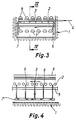
- the method is capable of producing more hemothermal glass so as to reduce a pleat effect (fig. 2).
- the hemothermal glass facilitates tempering of glass since the breakage of glasses in a chiller is decreased and the grain size of broken glass will be more uniform.
- the method also serves to facilitate the heating operation of difficult glasses, such as large quadratic glasses, since the furnace will be more hemothermal.
- the convection blasting itself will be more effective, since the power of blasting is not undermined by heating the rollers unnecessarily.
Landscapes
- Chemical & Material Sciences (AREA)
- Engineering & Computer Science (AREA)
- Materials Engineering (AREA)
- Organic Chemistry (AREA)
- Re-Forming, After-Treatment, Cutting And Transporting Of Glass Products (AREA)
Applications Claiming Priority (3)
| Application Number | Priority Date | Filing Date | Title |
|---|---|---|---|
| FI906398 | 1990-12-27 | ||
| FI906398A FI86407C (sv) | 1990-12-27 | 1990-12-27 | Förfarande och anordning för att utjämna temperaturprofilen i glasskiv or i en med valsar försedd ugn i en horisontalhärdningsanordning |
| PCT/FI1991/000404 WO1992012099A1 (en) | 1990-12-27 | 1991-12-20 | Method and apparatus for equalizing the temperature profile of glass sheets in a roller-equipped furnace included in a horizontal tempering plant |
Publications (2)
| Publication Number | Publication Date |
|---|---|
| EP0564489A1 EP0564489A1 (en) | 1993-10-13 |
| EP0564489B1 true EP0564489B1 (en) | 1995-11-29 |
Family
ID=8531648
Family Applications (1)
| Application Number | Title | Priority Date | Filing Date |
|---|---|---|---|
| EP92900936A Expired - Lifetime EP0564489B1 (en) | 1990-12-27 | 1991-12-20 | Method and apparatus for equalizing the temperature profile of glass sheets in a roller-equipped furnace included in a horizontal tempering plant |
Country Status (6)
| Country | Link |
|---|---|
| US (1) | US5368624A (sv) |
| EP (1) | EP0564489B1 (sv) |
| JP (1) | JP2666159B2 (sv) |
| DE (1) | DE69115054T2 (sv) |
| FI (1) | FI86407C (sv) |
| WO (1) | WO1992012099A1 (sv) |
Cited By (4)
| Publication number | Priority date | Publication date | Assignee | Title |
|---|---|---|---|---|
| US6490888B1 (en) | 1997-08-15 | 2002-12-10 | Kenneth Friedel | Semi-convective forced air method for tempering low “E” coated glass |
| EP0902762B1 (en) * | 1996-05-22 | 2003-07-23 | Uniglass Engineering Oy | Adjusting temperature of glass sheets in tempering furnace |
| US6901773B2 (en) | 2001-07-27 | 2005-06-07 | Tamglass Ltd. Oy | Semi-convective forced air system having amplified air nozzles for heating low “e” coated glass |
| DE102008025798A1 (de) | 2008-05-29 | 2009-12-03 | Zhongshan Fushan Glass Machinery Co., Ltd., Zhongshan | Rollenofen zum Erhitzen von Glasbahnen |
Families Citing this family (15)
| Publication number | Priority date | Publication date | Assignee | Title |
|---|---|---|---|---|
| FI97378C (sv) * | 1995-01-19 | 1996-12-10 | Glassrobots Oy | Förfarande för reglering och inriktning av värmeverkningar i en härdningsugn för glas och härdningsugn |
| FI101068B (sv) * | 1996-05-22 | 1998-04-15 | Uniglass Engineering Oy | Förfarande och anordning för uppvärmning av glas i en med valsar förse dd härdugn |
| FI100525B (sv) * | 1996-05-22 | 1997-12-31 | Uniglass Engineering Oy | Förfarande och anordning för reglering av kylluft i en glashärdningsma skin |
| FI100596B2 (sv) * | 1996-05-22 | 2002-09-10 | Uniglass Engineering Oy | Foerfarande och anordning foer uppvaermning av glasskivor i en med valsar foersedd haerdugn |
| DE19728787C1 (de) * | 1997-07-05 | 1998-09-03 | Glafurit Anlagenbau Gmbh | Rollenofen für die Erwärmung von Glasscheiben |
| US5951734A (en) * | 1997-08-15 | 1999-09-14 | Tgl Tempering Systems, Inc. | Semi-convective forced air system for tempering low E coated glass |
| FI110866B (sv) * | 2000-08-28 | 2003-04-15 | Tamglass Ltd Oy | Förfarande för uppvärmning av LowE-glasskivor i en härdningsung |
| CN100469719C (zh) * | 2001-07-11 | 2009-03-18 | 弗拉奇塔斯有限公司 | 将热引导到玻璃板的方法和对玻璃进行热处理的炉 |
| US20040237591A1 (en) * | 2003-05-28 | 2004-12-02 | Glasstech, Inc. | Furnace and method using electric resistance and forced convection for heating glass sheets |
| FI114697B (sv) * | 2003-06-11 | 2004-12-15 | Glassrobots Oy | Förfarande för observering och justering av uppvärmningseffekt i en härdningsugn för planglas |
| DE10330196B4 (de) * | 2003-07-03 | 2009-11-05 | Erdmann, Wolfgang | Anlage zur Wärmebehandlung von Glas |
| US8534096B2 (en) * | 2007-03-28 | 2013-09-17 | Glasstech, Inc. | Quench station and method for formed glass sheet quenching |
| US20110277506A1 (en) * | 2010-05-14 | 2011-11-17 | Glasstech, Inc. | Method and apparatus for heating glass sheets |
| CN102603174B (zh) * | 2012-04-11 | 2016-03-30 | 上海钰立机械有限公司 | 低辐射镀膜玻璃的强制对流加热装置 |
| WO2019002672A1 (en) * | 2017-06-27 | 2019-01-03 | Glaston Finland Oy | PROCESS FOR TEMPERING GLASS SHEETS |
Family Cites Families (5)
| Publication number | Priority date | Publication date | Assignee | Title |
|---|---|---|---|---|
| FR2291387A1 (fr) * | 1974-11-18 | 1976-06-11 | Saint Gobain | Dispositif de soufflage a commande individuelle des buses |
| FI62043C (fi) * | 1980-09-12 | 1982-11-10 | Tamglass Oy | Foerfarande och anordning foer att foerhindra boejningen av glsskivor i en med valsar foersedd ugn i en horisontalhaerd nigsanordning |
| US4620864A (en) * | 1984-07-23 | 1986-11-04 | Glasstech, Inc. | Glass sheet tempering utilizing heating and quenching performed in ambient at superatmospheric pressure |
| US4946491A (en) * | 1988-11-21 | 1990-08-07 | Glasstech, Inc. | Method and apparatus for glass tempering |
| FI83072C (sv) * | 1989-09-06 | 1991-05-27 | Tamglass Oy | Förfarande och anordning för att förhindra böjningen av glasskivor i e n med valsar försedd ugn i en horisontalhärdningsanordning |
-
1990
- 1990-12-27 FI FI906398A patent/FI86407C/sv active IP Right Grant
-
1991
- 1991-12-20 JP JP4502100A patent/JP2666159B2/ja not_active Expired - Lifetime
- 1991-12-20 EP EP92900936A patent/EP0564489B1/en not_active Expired - Lifetime
- 1991-12-20 WO PCT/FI1991/000404 patent/WO1992012099A1/en active IP Right Grant
- 1991-12-20 US US08/075,566 patent/US5368624A/en not_active Expired - Lifetime
- 1991-12-20 DE DE69115054T patent/DE69115054T2/de not_active Expired - Lifetime
Cited By (6)
| Publication number | Priority date | Publication date | Assignee | Title |
|---|---|---|---|---|
| EP0902762B1 (en) * | 1996-05-22 | 2003-07-23 | Uniglass Engineering Oy | Adjusting temperature of glass sheets in tempering furnace |
| US6490888B1 (en) | 1997-08-15 | 2002-12-10 | Kenneth Friedel | Semi-convective forced air method for tempering low “E” coated glass |
| US6901773B2 (en) | 2001-07-27 | 2005-06-07 | Tamglass Ltd. Oy | Semi-convective forced air system having amplified air nozzles for heating low “e” coated glass |
| DE102008025798A1 (de) | 2008-05-29 | 2009-12-03 | Zhongshan Fushan Glass Machinery Co., Ltd., Zhongshan | Rollenofen zum Erhitzen von Glasbahnen |
| DE102008025798B4 (de) * | 2008-05-29 | 2011-08-25 | Guangdong Fushan Glass Machinery Co., Ltd., Guangdong | Verfahren zum Betreiben eines Rollenofens |
| DE102008025798C5 (de) * | 2008-05-29 | 2015-08-06 | Guangdong Fushan Glass Machinery Co., Ltd. | Verfahren zum Betreiben eines Rollenofens |
Also Published As
| Publication number | Publication date |
|---|---|
| US5368624A (en) | 1994-11-29 |
| WO1992012099A1 (en) | 1992-07-23 |
| FI86407B (fi) | 1992-05-15 |
| JP2666159B2 (ja) | 1997-10-22 |
| DE69115054T2 (de) | 1996-04-18 |
| FI86407C (sv) | 1992-08-25 |
| EP0564489A1 (en) | 1993-10-13 |
| JPH06504255A (ja) | 1994-05-19 |
| FI906398A0 (fi) | 1990-12-27 |
| DE69115054D1 (de) | 1996-01-11 |
| FI906398A (fi) | 1992-05-15 |
Similar Documents
| Publication | Publication Date | Title |
|---|---|---|
| EP0564489B1 (en) | Method and apparatus for equalizing the temperature profile of glass sheets in a roller-equipped furnace included in a horizontal tempering plant | |
| JP3718532B2 (ja) | 板ガラスを曲げる方法及び装置 | |
| CA1112454A (en) | Method and apparatus for shaping glass sheets by roll forming | |
| EP1298096B1 (en) | Method and apparatus for heating glass sheets in preparation of tempering | |
| US4292065A (en) | Method and apparatus for shaping thermoplastic sheet material | |
| CA1326136C (en) | Apparatus and method for tempering glass sheets | |
| US4381933A (en) | Method and apparatus for shaping moving glass sheets by sagging followed by roll pressing | |
| CN1088044C (zh) | 用于加热欲回火或热强化的玻璃板的方法 | |
| EP0568053A1 (en) | Method and apparatus for bending and tempering a glass sheet | |
| US4824464A (en) | Process and apparatus for heating glass sheets | |
| CZ247490A3 (cs) | Zařízení pro ohýbání skleněných tabulí | |
| EP0902763B1 (en) | Heating glass sheets in tempering furnace | |
| WO1997044283A9 (en) | Heating glass sheets in tempering furnace | |
| US4878838A (en) | Process for the thermal treatment of more particularly substantially flat bodies of a ceramic material and continuous furnace for the performance of the process | |
| WO1998003439A1 (en) | A method for adjusting and directing heat effects in a glass tempering oven and an oven | |
| EP0416332B1 (en) | Method and apparatus for preventing the arching of glass sheets in the roller-equipped furnace of a horizontal tempering plant | |
| US3600151A (en) | Apparatus for tempering glass sheets | |
| US4936890A (en) | Convexing/tempering installation for the manufacture of glass not bent into convex shape on said installation | |
| US3526490A (en) | Method of bending glass on fluid support | |
| US3573890A (en) | Heated delivery system for sheet glass | |
| KR790001197B1 (ko) | 판유리의 열처리 방법 | |
| NO115739B (sv) | ||
| EP0932585A1 (en) | A method for adjusting and directing heat effects in a glass tempering oven and an oven |
Legal Events
| Date | Code | Title | Description |
|---|---|---|---|
| PUAI | Public reference made under article 153(3) epc to a published international application that has entered the european phase |
Free format text: ORIGINAL CODE: 0009012 |
|
| 17P | Request for examination filed |
Effective date: 19930625 |
|
| AK | Designated contracting states |
Kind code of ref document: A1 Designated state(s): CH DE FR GB IT LI |
|
| RAP1 | Party data changed (applicant data changed or rights of an application transferred) |
Owner name: TAMGLASS ENGINEERING OY |
|
| 17Q | First examination report despatched |
Effective date: 19950113 |
|
| GRAA | (expected) grant |
Free format text: ORIGINAL CODE: 0009210 |
|
| AK | Designated contracting states |
Kind code of ref document: B1 Designated state(s): CH DE FR GB IT LI |
|
| ITF | It: translation for a ep patent filed |
Owner name: JACOBACCI & PERANI S.P.A. |
|
| REF | Corresponds to: |
Ref document number: 69115054 Country of ref document: DE Date of ref document: 19960111 |
|
| REG | Reference to a national code |
Ref country code: CH Ref legal event code: NV Representative=s name: DIPL.-ING. HORST QUEHL PATENTANWALT |
|
| PGFP | Annual fee paid to national office [announced via postgrant information from national office to epo] |
Ref country code: CH Payment date: 19960228 Year of fee payment: 5 |
|
| ET | Fr: translation filed | ||
| PLBE | No opposition filed within time limit |
Free format text: ORIGINAL CODE: 0009261 |
|
| STAA | Information on the status of an ep patent application or granted ep patent |
Free format text: STATUS: NO OPPOSITION FILED WITHIN TIME LIMIT |
|
| 26N | No opposition filed | ||
| PG25 | Lapsed in a contracting state [announced via postgrant information from national office to epo] |
Ref country code: LI Effective date: 19961231 Ref country code: CH Effective date: 19961231 |
|
| REG | Reference to a national code |
Ref country code: CH Ref legal event code: PL |
|
| REG | Reference to a national code |
Ref country code: GB Ref legal event code: IF02 |
|
| REG | Reference to a national code |
Ref country code: FR Ref legal event code: CD |
|
| PGFP | Annual fee paid to national office [announced via postgrant information from national office to epo] |
Ref country code: FR Payment date: 20110104 Year of fee payment: 20 |
|
| PGFP | Annual fee paid to national office [announced via postgrant information from national office to epo] |
Ref country code: IT Payment date: 20101227 Year of fee payment: 20 Ref country code: GB Payment date: 20101221 Year of fee payment: 20 |
|
| PGFP | Annual fee paid to national office [announced via postgrant information from national office to epo] |
Ref country code: DE Payment date: 20101222 Year of fee payment: 20 |
|
| REG | Reference to a national code |
Ref country code: DE Ref legal event code: R071 Ref document number: 69115054 Country of ref document: DE |
|
| REG | Reference to a national code |
Ref country code: DE Ref legal event code: R071 Ref document number: 69115054 Country of ref document: DE |
|
| REG | Reference to a national code |
Ref country code: GB Ref legal event code: PE20 Expiry date: 20111219 |
|
| PG25 | Lapsed in a contracting state [announced via postgrant information from national office to epo] |
Ref country code: GB Free format text: LAPSE BECAUSE OF EXPIRATION OF PROTECTION Effective date: 20111219 |
|
| PG25 | Lapsed in a contracting state [announced via postgrant information from national office to epo] |
Ref country code: DE Free format text: LAPSE BECAUSE OF EXPIRATION OF PROTECTION Effective date: 20111221 |