EP0561767B1 - Druckregel- und schliessventil für einen turbinenmotor - Google Patents
Druckregel- und schliessventil für einen turbinenmotor Download PDFInfo
- Publication number
- EP0561767B1 EP0561767B1 EP89909643A EP89909643A EP0561767B1 EP 0561767 B1 EP0561767 B1 EP 0561767B1 EP 89909643 A EP89909643 A EP 89909643A EP 89909643 A EP89909643 A EP 89909643A EP 0561767 B1 EP0561767 B1 EP 0561767B1
- Authority
- EP
- European Patent Office
- Prior art keywords
- piston
- fuel
- shut
- outlet port
- operational
- Prior art date
- Legal status (The legal status is an assumption and is not a legal conclusion. Google has not performed a legal analysis and makes no representation as to the accuracy of the status listed.)
- Expired - Lifetime
Links
- 230000001105 regulatory effect Effects 0.000 title description 3
- 239000000446 fuel Substances 0.000 claims abstract description 61
- 239000012530 fluid Substances 0.000 claims abstract description 18
- 238000004891 communication Methods 0.000 claims abstract description 15
- 230000002093 peripheral effect Effects 0.000 claims description 6
- 238000007789 sealing Methods 0.000 claims description 5
- 230000001681 protective effect Effects 0.000 claims 2
- 230000000977 initiatory effect Effects 0.000 claims 1
- 230000003628 erosive effect Effects 0.000 description 2
- 230000000694 effects Effects 0.000 description 1
- 230000007704 transition Effects 0.000 description 1
Images


Classifications
-
- F—MECHANICAL ENGINEERING; LIGHTING; HEATING; WEAPONS; BLASTING
- F16—ENGINEERING ELEMENTS AND UNITS; GENERAL MEASURES FOR PRODUCING AND MAINTAINING EFFECTIVE FUNCTIONING OF MACHINES OR INSTALLATIONS; THERMAL INSULATION IN GENERAL
- F16K—VALVES; TAPS; COCKS; ACTUATING-FLOATS; DEVICES FOR VENTING OR AERATING
- F16K11/00—Multiple-way valves, e.g. mixing valves; Pipe fittings incorporating such valves
- F16K11/02—Multiple-way valves, e.g. mixing valves; Pipe fittings incorporating such valves with all movable sealing faces moving as one unit
- F16K11/06—Multiple-way valves, e.g. mixing valves; Pipe fittings incorporating such valves with all movable sealing faces moving as one unit comprising only sliding valves, i.e. sliding closure elements
- F16K11/065—Multiple-way valves, e.g. mixing valves; Pipe fittings incorporating such valves with all movable sealing faces moving as one unit comprising only sliding valves, i.e. sliding closure elements with linearly sliding closure members
- F16K11/07—Multiple-way valves, e.g. mixing valves; Pipe fittings incorporating such valves with all movable sealing faces moving as one unit comprising only sliding valves, i.e. sliding closure elements with linearly sliding closure members with cylindrical slides
- F16K11/0712—Multiple-way valves, e.g. mixing valves; Pipe fittings incorporating such valves with all movable sealing faces moving as one unit comprising only sliding valves, i.e. sliding closure elements with linearly sliding closure members with cylindrical slides comprising particular spool-valve sealing means
-
- F—MECHANICAL ENGINEERING; LIGHTING; HEATING; WEAPONS; BLASTING
- F02—COMBUSTION ENGINES; HOT-GAS OR COMBUSTION-PRODUCT ENGINE PLANTS
- F02C—GAS-TURBINE PLANTS; AIR INTAKES FOR JET-PROPULSION PLANTS; CONTROLLING FUEL SUPPLY IN AIR-BREATHING JET-PROPULSION PLANTS
- F02C9/00—Controlling gas-turbine plants; Controlling fuel supply in air- breathing jet-propulsion plants
- F02C9/26—Control of fuel supply
- F02C9/263—Control of fuel supply by means of fuel metering valves
-
- F—MECHANICAL ENGINEERING; LIGHTING; HEATING; WEAPONS; BLASTING
- F16—ENGINEERING ELEMENTS AND UNITS; GENERAL MEASURES FOR PRODUCING AND MAINTAINING EFFECTIVE FUNCTIONING OF MACHINES OR INSTALLATIONS; THERMAL INSULATION IN GENERAL
- F16K—VALVES; TAPS; COCKS; ACTUATING-FLOATS; DEVICES FOR VENTING OR AERATING
- F16K17/00—Safety valves; Equalising valves, e.g. pressure relief valves
- F16K17/02—Safety valves; Equalising valves, e.g. pressure relief valves opening on surplus pressure on one side; closing on insufficient pressure on one side
- F16K17/04—Safety valves; Equalising valves, e.g. pressure relief valves opening on surplus pressure on one side; closing on insufficient pressure on one side spring-loaded
- F16K17/0446—Safety valves; Equalising valves, e.g. pressure relief valves opening on surplus pressure on one side; closing on insufficient pressure on one side spring-loaded with an obturating member having at least a component of their opening and closing motion not perpendicular to the closing faces
- F16K17/046—Safety valves; Equalising valves, e.g. pressure relief valves opening on surplus pressure on one side; closing on insufficient pressure on one side spring-loaded with an obturating member having at least a component of their opening and closing motion not perpendicular to the closing faces the valve being of the gate valve type or the sliding valve type
-
- Y—GENERAL TAGGING OF NEW TECHNOLOGICAL DEVELOPMENTS; GENERAL TAGGING OF CROSS-SECTIONAL TECHNOLOGIES SPANNING OVER SEVERAL SECTIONS OF THE IPC; TECHNICAL SUBJECTS COVERED BY FORMER USPC CROSS-REFERENCE ART COLLECTIONS [XRACs] AND DIGESTS
- Y10—TECHNICAL SUBJECTS COVERED BY FORMER USPC
- Y10T—TECHNICAL SUBJECTS COVERED BY FORMER US CLASSIFICATION
- Y10T137/00—Fluid handling
- Y10T137/7722—Line condition change responsive valves
- Y10T137/7837—Direct response valves [i.e., check valve type]
- Y10T137/7866—Plural seating
- Y10T137/7867—Sequential
- Y10T137/7868—Resilient gasket
-
- Y—GENERAL TAGGING OF NEW TECHNOLOGICAL DEVELOPMENTS; GENERAL TAGGING OF CROSS-SECTIONAL TECHNOLOGIES SPANNING OVER SEVERAL SECTIONS OF THE IPC; TECHNICAL SUBJECTS COVERED BY FORMER USPC CROSS-REFERENCE ART COLLECTIONS [XRACs] AND DIGESTS
- Y10—TECHNICAL SUBJECTS COVERED BY FORMER USPC
- Y10T—TECHNICAL SUBJECTS COVERED BY FORMER US CLASSIFICATION
- Y10T137/00—Fluid handling
- Y10T137/7722—Line condition change responsive valves
- Y10T137/7837—Direct response valves [i.e., check valve type]
- Y10T137/7904—Reciprocating valves
- Y10T137/7922—Spring biased
- Y10T137/7925—Piston-type valves
Definitions
- This invention relates to a shut off/pressure regulating valve for a turbine engine.
- the valve has a shuttle piston which moves in a sleeve in response to a pressure differential between an operational fuel and a control fuel to allow operational fuel to flow from an inlet port to an outlet port through radial openings in the sleeve.
- a resilient member moves the piston past the radial openings to interrupt fluid communication through these openings.
- a seal carried by the piston engages a ramp on the sleeve and face on the piston engages a seal on a seat member to prevent fluid communication from the inlet port and a control port to the outlet port through the clearance between the piston and sleeve to thereafter completely interrupt the communication of fuel to the turbine engine.
- shut off and pressure regulator valve While retaining the relatively friction free operation of the shuttle piston, we have developed a sealing arrangement for a shut off and pressure regulator valve having a piston which freely moves in a bore in response to a pressure differential and the operational clearance is only sealed during an inoperative condition.
- the shut off and pressure regulator valve in conjunction with a metering valve control the supply of fuel to a turbine.
- the shut off and pressure regulator valve has a housing with a bore therein.
- the bore has an inlet port connected to a receive pressurized operational fuel, a control port connected to receive a control fuel and an outlet port connected to the turbine.
- the housing has a shoulder located in the bore between the inlet and outlet ports.
- a piston is located in the bore to separate between the inlet port and outlet port to separate the bore into a supply chamber and a control chamber. Operational fuel in the supply chamber and control fuel in the control chamber create a pressure differential across the piston.
- a spring located between an end cap and the piston urges the piston toward a stationary seal on the shoulder in opposition to the pressure differential.
- a clearance between the piston and bore allows the piston to freely move without substantial frictional resistance when operational fuel is supplied to the turbine.
- An advantage of this invention occurs through a sealing arrangement which effectively prevents the flow of fuel in a shut off position but does not restrict essentially friction free operational movement of the pressure regulating piston.
- a further advantage of this invention occurs through the use of a sleeve having a series of radial openings located a distance away from a seat to define a flow path which reduces the possibility of erosion of the seal caused by the flow of fuel through a shut off valve.
- the shut off valve 10, shown in Figure 1 is designed to be included in a fuel system for a turbine engine of an aircraft.
- the shut off valve is located down stream from a metering valve 12 which is controlled by an input from a electronic control unit (ecu) in the aircraft.
- ecu electronice control unit
- the shut off valve 10 has a housing 14 with an inlet port 16 connected to an outlet chamber 18 of the metering valve 12, a control port 20 connected to receive control fuel from a regulator 22, and an outlet port 24 connected to the turbine engine.
- Housing 14 has a bore 26 that extends from an opening 25 to a shoulder 30 adjacent the inlet port 16.
- Housing 14 has an annular groove 28 which forms a smooth entry for fluid from the bore 26 into the outlet port 24.
- An annular seat member 32 located in bore 26 adjacent shoulder 30 has a peripheral seal 34 which engages bore 26 and an annular groove 36 located on a face 38.
- An axial opening 40 in seat member 32 has a tapered surface 42 to provide for a smooth transition for fuel from supply chamber 18 of the metering valve 12 into bore 26.
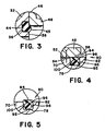
- a cylindrical seal member 44 is located in groove 36 of the seat member 32. After a flange 46 on a first end of sleeve 48 engages seal member 44, as best shown in Figure 3, about 15 percent of seal member 44 protrudes past face 38.
- sleeve 48 has a plurality of radial openings 50 (only one is shown) located adjacent the flange 46. Openings 50 are located a sufficient distance from axial opening 40 to reduce the creation of turbulence that could erode the seal 44 during the communication of fuel to outlet port 24.
- Sleeve 48 which extends into bore 26 past the control port 20 has a tapered surface 56 on a second end. Tapered or sloped surface 56 extends from the interior surface 52 of the sleeve 48.
- An annular guide 54 which engages flange 46 has a cylindrical section 58 that extends past opening 50 in the sleeve 48 to deflect fuel flow from the openings 50 toward the outlet port 24.
- the deflection of fuel by cylindrical section 58 prevents cavitation in the fuel due to an extreme pressure drop across openings 50 from eroding bore 26.
- a cylindrical member 60 has a seal 62 which engages bore 26 and a plurality of openings 64 that empty into annular groove 28.
- End cap 66 which screws into housing 14 to close opening 25 to seal bore 26.
- End cap 66 has an end 68 that engages cylindrical member 60 to hold sleeve 48 against seat 32.
- a shuttle piston 70 located in sleeve 48 has a wall 72 which separates bore 26 into an operational chamber 74 and a control chamber 76.
- Shuttle piston 48 has a first end 80 and a second end 82.
- a groove 78 located on the peripheral surface 84 of piston 70 retains a seal member 90.
- the diameter of the shuttle piston 70 is such that peripheral surface 84 is less than the interior surface 52 of sleeve 48. The difference in diameters or clearance is exaggerated and illustrated by "x" shown in Figure 4.
- Seal member 90 has a first section made up of annular rubber ring 92 and a second section made up of a plastic retainer 94.
- Retainer 94 has a semi-spherical socket 96 with legs 98 and 100 that engage the side walls of groove 78 in shuttle piston 70.
- control fluid from regulator 22 is operational fuel communicated to control chamber 76.
- Piston 13 associated with metering valve 12 is moved past opening 11 from the supply pump 9 to interrupt the flow of fuel into supply chamber 18.
- Restrictive orifice 19 in bleed passage 21 allows fuel to flow from supply chamber 18.
- the fluid pressure in supply chamber 18 is reduced to a level that is less than the operational control fuel from regulator 22 and thus a closure pressure differential is created across wall 72.
- This pressure differential and spring 102 move shuttle piston 20 into engagement with seat member 32.
- the first end 80 of shuttle piston 70 moves from a position, as shown in figure 2, past opening 50 in sleeve 48 the flow of fuel from the supply chamber 18 of metering valve 12 essentially terminates.
- control fluid in chamber 76 and supply fuel in chamber 18 may still flow through clearance "x" to opening 50.
- retainer 94 initially engages and thereafter moves down ramp 56 causing the o-ring seal 92 to flatten out in a manner shown in Figure 4 to prevent operational fuel from flowing from the control chamber 76 to the outlet port 24.
- end 80 of shuttle piston 70 engages face 38 on seat member 32, protrusion 45 on seal 44 is compressed into groove 35 to prevent communication of operational fuel from chamber 74 through the clearance "x" to the outlet port 24.
- the operational pressure differential continually moves piston 70 to regulate and maintain the fluid pressure in supply chamber 18 within a desired range.
- piston 70 is essentially floating on a surface of control fluid located in the clearance "x" such that frictional resistance to movement of the piston 70 is eliminated or negligible.
- the metering valve 12 controls the quantity of operational fuel that is supplied to the turbine.
- the guide surfaces 58 and spacing of the opening 50 in the sleeve 48 and openings 64 in cylindrical member 60 cooperate to prevent the removal of seal 44 from groove 36 in the seat member 32.
- a control member When the operator desires to shut down the turbine, a control member is moved to a shut off position.
- the ecu 23 provides the metering valve 12 with an input that moves piston 13 to close port 11.
- port 11 closes fluid from supply chamber 18 flows to the outlet port 24 until the pressure differential across wall 72 is reduced such that spring 102 can moves piston 70 against face 38 of seat 32 and seal 90 into engagement with ramp 56 to completely terminate fuel flow through outlet port 24 as shown in figure 1.
- orifice 19 allows such fuel to flow to the return through port 21 to prevent pressure build up such that spring 102 would be overcome and shuttle piston 70 moved away from seat member 23.
- the size of orifice 19 is selected to have essentially no effect on the development of fluid pressure in supply chamber 18 once piston 13 moves past port 11.
Landscapes
- Engineering & Computer Science (AREA)
- General Engineering & Computer Science (AREA)
- Mechanical Engineering (AREA)
- Chemical & Material Sciences (AREA)
- Combustion & Propulsion (AREA)
- Fuel-Injection Apparatus (AREA)
- Safety Valves (AREA)
Claims (7)
- Druckregel- und Schließventil (10) zur Verwendung mit einem Dosierventil (12), welches einem Turbinenmotor Kraftstoff zuführt, wobei das Ventil (10) ein Gehäuse (14) mit einer sich darin befindlichen Bohrung (26) umfaßt, wobei ein Einlaßanschluß (16) so verbunden ist, daß er Betriebskraftstoff unter Druck empfängt, ferner umfassend einen Regelanschluß (20), der so verbunden ist, daß er einen Regelkraftstoff empfängt und einen Auslaßanschluß (24), der so verbunden ist, daß er die Turbine mit Betriebskraftstoff versorgt, wobei die Bohrung (26) eine Schulter (30) aufweist, die sich zwischen den Einlaß- (16) und Auslaßanschlüssen (24) befindet, mit einen Kolben (70) zur Unterteilungg der Bohrung (26) in eine Regelkammer (76) und eine Zufuhrkammer (74), welche den Betriebskraftstoff aufweist, mit einer Endkappe (66), die an dem Gehäuse (14) befestigt ist, wobei der Kolben (70) ein erstes Ende (80) aufweist, welches dem Betriebskraftstoff in der Zufuhrkammer ausgesetzt ist sowie ein zweites Ende (82), welches dem Regelkraftstoff in der Regelkammer ausgesetzt ist, wobei der Kolben (70) auf einen vorbestimmten Druckunterschied zwischen dem Betriebskraftstoff und dem Regelkraftstoff durch Bewegung anspricht, um es zu ermöglichen, daß Betriebskraftstoff von der Zufuhrkammer an den Auslaßanschluß (24) fließt, mit einem elastischen Element (102), welches sich zwischen der Endkappe (66) und dem Kolben (70) befindet, um den Kolben (70) entgegengesetzt zu dem vorbestimmten Druckunterschied in Richtung der Schulter (30) zu drängen, und mit einer Dichtungsanordnung zur Unterbrechung der Strömungsverbindung des Betriebskraftstoffes von der Zufuhrkammer (74) an den Auslaßanschluß (24) beim Eingriff des ersten Endes (80) des Kolbens (70) mit der Schulter (30), wobei die Dichtungsanordnung durch ein Sitzelement (32) gekennzeichnet ist, das sich neben der Schulter (30) befindet und das eine Fläche (38) mit einer sich darin befindenden ringförmigen Rille (36) aufweist, ein erstes Dichtungselement (44), das sich in der ringförmigen Rille (36) befindet, ein Muffenelement (48), das sich in der Bohrung (26) befindet und einen Flansch (46) an einem ersten Ende aufweist, welcher das erste Dichtungselement (44) in der ringförmigen Rille (36) hält und eine Rampe (56), die sich an einem zweiten Ende befindet, wobei das Muffenelement (48) eine Mehrzahl radialer Öffnungen (50) aufweist, durch welche die Zufuhrkammer (74) mit dem Auslaßanschluß (24) verbunden ist, mit einem zweiten Dichtungselement (90), welches sich in einer peripheren Rille (78) an dem Kolben (70) befindet, wobei die elastische Einrichtung (102) bei der Überwindung des vorbestimmten Druckunterschieds das erste Ende (80) des Kolbens (70) an den radialen Öffnungen (50) in dem Muffenelement (48) vorbei bewegt und das zweite Dichtungselement (90) in Eingriff mit der Rampe (56) an dem Muffenelement (48), wobei sich das zweite Dichtungselement (90) an die Rampe (56) bewegt, um Flüssigkeitsübertragungen des Regelkraftstoffs von der Regelkammer (76) zu dem Auslaßanschluß (24) entlang einem ersten Strömungsweg zu vermeiden, der durch den Betriebsabstand (x) zwischen dem Kolben (70) und dem Muffenelement (48) gestaltet ist, wobei sich das erste Ende (80) des Kolbens (70) in Eingriff mit dem ersten Dichtungselement (44) bewegt, um eine Übertragung von Betriebskraftstoff von der Zufuhrkammer (74) zu dem Auslaßanschluß (24) entlang einem zweiten Strömungsweg zu vermeiden, der durch den Betriebsabstand (x) zwischen dem Kolben (70) und dem Muffenelement (48) gestaltet ist, um die Strömungsverbindung von Kraftstoff aus dem Auslaßanschluß (24) und dementsprechend zu dem Turbinenmotor danach vollständig zu unterbrechen.
- Druckregel- und Schließventil (10) nach Anspruch 1, wobei das zweite Dichtungselement (90) ferner durch eine Schutzkappe (94) gekennzeichnet ist, welche einen ringförmigen Gummiring (92) umgibt, um eine Beschädigung der Umfangsoberfläche des ringförmigen Gummirings (92) beim Eingriff mit der Rampe (56) zu vermeiden.
- Druckregel- und Schließventil (10) nach Anspruch 1, wobei das zweite Dichtungselement (90) ferner durch eine Schutzkappe (94) gekennzeichnet ist, welche einen ringförmigen Gummiring (92) umgibt, um den Gummiring (92) in der peripheren Rille (78) zu halten.
- Druckregel- und Schließventil (10) nach Anspruch 1, wobei das Muffenelement (48) durch ein erstes zylinderförmiges Element (54) gekennzeichnet ist, welches mit einem Flansch (46) eingreift und wobei das Muffenelement durch ein zweites zylinderförmiges Element (60) gekennzeichnet ist, das sich zwischen dem ersten zylinderförmigen Element (54) und der Endkappe (66) befindet, wobei das zweite zylinderförmige Element (60) eine Mehrzahl radialer Öffnungen (64) aufweist, durch welche die Öffnungen (50) in dem Muffenelement (48) mit dem Auslaßanschluß (24) verbunden sind, wobei das erste zylinderförmige Element (54) eine Führungsoberfläche (58) aufweist, um den Flüssigkeitsstromm von der Zufuhrkammer (74) durch die Öffnungen (50) und (64) zu leiten, ohne daß dabei Turbulenzen entstehen.
- Druckregel- und Schließventil (10) nach Anspruch 4, wobei der Abstand (x) durch den Durchmesserunterschied zwischen dem Kolben (70) und dem Muffenelement (48) gekennzeichnet ist, wodurch sich der Kolben (70) frei bewegen kann, und zwar im wesentlichen ohne Reibungswiderstand.
- Druckregel- und Schließventil (10) nach Anspruch 5, wobei die Anfangskolbenbewegung (70), welche von der Schulter (32) weggeht, dadurch gekennzeichnet ist, daß sich das erste Ende (80) von dem ersten Dichtungselement (44) um eine vorbestimmte Strecke wegbewegt, bevor die Strömungsverbindung durch die radialen Öffnungen (50) in dem Muffenelement (48) eingeleitet wird, um so eine Abnutzung der ersten Dichtung (44) zu verringern, die durch den Flüssigkeitstrom zu dem Auslaßanschluß (24) verursacht werden könnte.
- Druckregel- und Schließventil (10) nach Anspruch 6, wobei das Muffenelement (48) ferner dadurch gekennzeichnet ist, daß es sich über den Regelanschluß (20) hinaus erstreckt, um die Einführung auf den Kolben (70) einwirkender Radialkräfte auf die Übertragung des Kraftstoffs an die Regelkammer (76) zu vermeiden.
Applications Claiming Priority (3)
| Application Number | Priority Date | Filing Date | Title |
|---|---|---|---|
| US07/233,106 US4876857A (en) | 1988-08-15 | 1988-08-15 | Shut off/pressure regulating valve for turbine engine |
| US233106 | 1988-08-15 | ||
| PCT/US1989/003237 WO1990001626A1 (en) | 1988-08-15 | 1989-07-26 | Shut off/pressure regulating valve for turbine engine |
Publications (2)
| Publication Number | Publication Date |
|---|---|
| EP0561767A1 EP0561767A1 (de) | 1993-09-29 |
| EP0561767B1 true EP0561767B1 (de) | 1994-09-14 |
Family
ID=22875905
Family Applications (1)
| Application Number | Title | Priority Date | Filing Date |
|---|---|---|---|
| EP89909643A Expired - Lifetime EP0561767B1 (de) | 1988-08-15 | 1989-07-26 | Druckregel- und schliessventil für einen turbinenmotor |
Country Status (6)
| Country | Link |
|---|---|
| US (1) | US4876857A (de) |
| EP (1) | EP0561767B1 (de) |
| JP (1) | JPH0670377B2 (de) |
| CA (1) | CA1307119C (de) |
| DE (1) | DE68918293T2 (de) |
| WO (1) | WO1990001626A1 (de) |
Families Citing this family (23)
| Publication number | Priority date | Publication date | Assignee | Title |
|---|---|---|---|---|
| US5020315A (en) * | 1989-08-08 | 1991-06-04 | United Technologies Corporation | Multiple function fuel valve and system |
| JP2836163B2 (ja) * | 1989-12-21 | 1998-12-14 | 住友電気工業株式会社 | 流量制御弁 |
| US5118075A (en) * | 1991-02-12 | 1992-06-02 | Allied-Signal Inc. | Seal arrangement for a metering valve |
| US5339636A (en) * | 1992-12-04 | 1994-08-23 | United Technologies Corporation | Fuel splitter valve assembly for gas turbine |
| JP3150012B2 (ja) * | 1993-07-29 | 2001-03-26 | 株式会社ワイ・テイ・エス | スプール弁 |
| FR2711433B1 (fr) * | 1993-10-20 | 1995-12-01 | Snecma | Régulateur coaxial de débit. |
| US5417402A (en) * | 1994-02-10 | 1995-05-23 | Alliedsignal Inc. | Shutoff and pressure regulating valve |
| US5772182A (en) * | 1996-04-17 | 1998-06-30 | United Technologies Corporation | Fuel flow control valve |
| US7322373B2 (en) * | 2003-08-05 | 2008-01-29 | Honeywell International, Inc. | High accuracy low leakage valve for high pressure applications |
| US20060185737A1 (en) * | 2005-01-24 | 2006-08-24 | Matthew Williamson | Pressure relief valve with debris trap |
| US8316880B2 (en) * | 2009-05-08 | 2012-11-27 | Hamilton Sundstrand Corporation | Oil filter bypass valve assembly for a generator |
| US10041407B2 (en) | 2011-03-29 | 2018-08-07 | General Electric Company | System and method for air extraction from gas turbine engines |
| US9453462B2 (en) * | 2012-08-31 | 2016-09-27 | Hamilton Sundstrand Corporation | Filter bypass valve |
| US9175789B2 (en) | 2012-10-23 | 2015-11-03 | Hamilton Sundstrand Corporation | Pressure regulating valve |
| US9732864B2 (en) * | 2014-05-14 | 2017-08-15 | Hamilton Sundstrand Corporation | Contamination resistant cartridge valve |
| GB201901548D0 (en) | 2019-02-05 | 2019-03-27 | Rolls Royce Plc | Valve arrangement for a fuel system |
| US20220325709A1 (en) * | 2019-07-11 | 2022-10-13 | Eagle Industry Co., Ltd. | Capacity control valve |
| DE102019133667B4 (de) * | 2019-12-10 | 2025-08-28 | Schaeffler Technologies AG & Co. KG | Vorrichtung zur Regelung von Drücken eines Strömungsmittels mit einem Ventil |
| EP3907397B1 (de) | 2020-03-30 | 2023-06-07 | Hamilton Sundstrand Corporation | Kraftstofffilteranordnung |
| EP3907396B1 (de) | 2020-03-30 | 2023-06-07 | Hamilton Sundstrand Corporation | Kraftstofffilteranordnung |
| EP3907398B1 (de) | 2020-03-30 | 2023-05-03 | Hamilton Sundstrand Corporation | Kraftstofffilteranordnung |
| EP3904667B1 (de) | 2020-04-28 | 2024-08-14 | Hamilton Sundstrand Corporation | Kraftstofffilteranordnung |
| EP4154961B1 (de) | 2021-09-24 | 2024-10-30 | Collins Engine Nozzles, Inc. | Filterventilanordnung |
Family Cites Families (11)
| Publication number | Priority date | Publication date | Assignee | Title |
|---|---|---|---|---|
| US2694406A (en) * | 1952-11-14 | 1954-11-16 | Edgar H Ayers | Constant flow fuel valve |
| US3106934A (en) * | 1958-12-24 | 1963-10-15 | Bendix Corp | Integrating and proportional flow control apparatus |
| US3092133A (en) * | 1959-11-09 | 1963-06-04 | Arkla Ind | Fluid regulating valve |
| US3085588A (en) * | 1960-10-31 | 1963-04-16 | Gen Electric | Valve with sealing means |
| US3339574A (en) * | 1964-05-29 | 1967-09-05 | Gen Electric | Pressurizing and drain valve |
| US3294111A (en) * | 1965-06-01 | 1966-12-27 | Us Industries Inc | Relief valve |
| US3667504A (en) * | 1970-12-28 | 1972-06-06 | Deere & Co | Zero-leakage spool valve |
| FR2415763A1 (fr) * | 1978-01-30 | 1979-08-24 | Proengin Sarl | Perfectionnements apportes aux vannes a tiroir |
| GB2125110A (en) * | 1982-08-11 | 1984-02-29 | United Technologies Corp | Gas turbine augmentor fuel control system |
| GB2180005B (en) * | 1985-09-04 | 1989-03-01 | Rolls Royce | Fuel systems for gas turbine engines |
| DE8626721U1 (de) * | 1986-10-08 | 1988-05-19 | Mannesmann Rexroth GmbH, 8770 Lohr | 2/2-Wegeventil |
-
1988
- 1988-08-15 US US07/233,106 patent/US4876857A/en not_active Expired - Lifetime
-
1989
- 1989-07-26 JP JP1509041A patent/JPH0670377B2/ja not_active Expired - Fee Related
- 1989-07-26 WO PCT/US1989/003237 patent/WO1990001626A1/en not_active Ceased
- 1989-07-26 DE DE68918293T patent/DE68918293T2/de not_active Expired - Fee Related
- 1989-07-26 EP EP89909643A patent/EP0561767B1/de not_active Expired - Lifetime
- 1989-08-10 CA CA000608007A patent/CA1307119C/en not_active Expired - Lifetime
Also Published As
| Publication number | Publication date |
|---|---|
| WO1990001626A1 (en) | 1990-02-22 |
| JPH0670377B2 (ja) | 1994-09-07 |
| CA1307119C (en) | 1992-09-08 |
| EP0561767A1 (de) | 1993-09-29 |
| DE68918293D1 (de) | 1994-10-20 |
| US4876857A (en) | 1989-10-31 |
| DE68918293T2 (de) | 1995-03-30 |
| JPH03502124A (ja) | 1991-05-16 |
Similar Documents
| Publication | Publication Date | Title |
|---|---|---|
| US4876857A (en) | Shut off/pressure regulating valve for turbine engine | |
| US5417402A (en) | Shutoff and pressure regulating valve | |
| US5383647A (en) | Gas-injection valve for internal combustion engine | |
| US4182354A (en) | Method and apparatus for flow diversion in a high pressure fluid delivery system | |
| US6877306B2 (en) | Nozzle assembly with flow divider and ecology valve | |
| US3443760A (en) | Fail-safe fuel injection nozzle | |
| US4165951A (en) | Water pressure booster system and control valve therefor | |
| US3478776A (en) | Pressure regulating device for fluid dispensing systems | |
| US5327720A (en) | Differential pressure regulator valve | |
| GB2023727A (en) | Fuel injector nozzle | |
| US4932205A (en) | Bypass valve and visual indicator for a fuel system | |
| GB2256031A (en) | Automatic bleed valve | |
| US5132009A (en) | Filter for a fuel system | |
| US3500864A (en) | Hydrant pressure regulator | |
| US5118075A (en) | Seal arrangement for a metering valve | |
| US4819688A (en) | Volumetric, self-resetting, hydraulic fuse | |
| EP0412929A2 (de) | Brennstoffsregelung unter Verwendung eines Ventils mit mehreren Funktionen | |
| US4467828A (en) | Fluid regulator | |
| US4268008A (en) | Push button faucet | |
| EP0145436B1 (de) | Überdruckventil | |
| US4665942A (en) | Hydraulic pressure fuse | |
| JPH01134029A (ja) | 燃料制御装置 | |
| US3853142A (en) | Flow control system | |
| US4962786A (en) | Hydraulic fuse with pressure regulator | |
| US4520843A (en) | Flow control valve |
Legal Events
| Date | Code | Title | Description |
|---|---|---|---|
| PUAI | Public reference made under article 153(3) epc to a published international application that has entered the european phase |
Free format text: ORIGINAL CODE: 0009012 |
|
| 17P | Request for examination filed |
Effective date: 19910207 |
|
| AK | Designated contracting states |
Kind code of ref document: A1 Designated state(s): DE GB |
|
| 17Q | First examination report despatched |
Effective date: 19931102 |
|
| GRAA | (expected) grant |
Free format text: ORIGINAL CODE: 0009210 |
|
| AK | Designated contracting states |
Kind code of ref document: B1 Designated state(s): DE GB |
|
| REF | Corresponds to: |
Ref document number: 68918293 Country of ref document: DE Date of ref document: 19941020 |
|
| RAP2 | Party data changed (patent owner data changed or rights of a patent transferred) |
Owner name: ALLIEDSIGNAL INC. |
|
| PLBE | No opposition filed within time limit |
Free format text: ORIGINAL CODE: 0009261 |
|
| STAA | Information on the status of an ep patent application or granted ep patent |
Free format text: STATUS: NO OPPOSITION FILED WITHIN TIME LIMIT |
|
| 26N | No opposition filed | ||
| REG | Reference to a national code |
Ref country code: GB Ref legal event code: IF02 |
|
| PGFP | Annual fee paid to national office [announced via postgrant information from national office to epo] |
Ref country code: DE Payment date: 20030731 Year of fee payment: 15 |
|
| PG25 | Lapsed in a contracting state [announced via postgrant information from national office to epo] |
Ref country code: DE Free format text: LAPSE BECAUSE OF NON-PAYMENT OF DUE FEES Effective date: 20050201 |
|
| PGFP | Annual fee paid to national office [announced via postgrant information from national office to epo] |
Ref country code: GB Payment date: 20080616 Year of fee payment: 20 |
|
| REG | Reference to a national code |
Ref country code: GB Ref legal event code: PE20 Expiry date: 20090725 |
|
| PG25 | Lapsed in a contracting state [announced via postgrant information from national office to epo] |
Ref country code: GB Free format text: LAPSE BECAUSE OF EXPIRATION OF PROTECTION Effective date: 20090725 |