EP3907397B1 - Kraftstofffilteranordnung - Google Patents
Kraftstofffilteranordnung Download PDFInfo
- Publication number
- EP3907397B1 EP3907397B1 EP21163267.4A EP21163267A EP3907397B1 EP 3907397 B1 EP3907397 B1 EP 3907397B1 EP 21163267 A EP21163267 A EP 21163267A EP 3907397 B1 EP3907397 B1 EP 3907397B1
- Authority
- EP
- European Patent Office
- Prior art keywords
- filter
- fuel
- outlet
- inlet
- chamber
- Prior art date
- Legal status (The legal status is an assumption and is not a legal conclusion. Google has not performed a legal analysis and makes no representation as to the accuracy of the status listed.)
- Active
Links
Images


Classifications
-
- F—MECHANICAL ENGINEERING; LIGHTING; HEATING; WEAPONS; BLASTING
- F02—COMBUSTION ENGINES; HOT-GAS OR COMBUSTION-PRODUCT ENGINE PLANTS
- F02M—SUPPLYING COMBUSTION ENGINES IN GENERAL WITH COMBUSTIBLE MIXTURES OR CONSTITUENTS THEREOF
- F02M37/00—Apparatus or systems for feeding liquid fuel from storage containers to carburettors or fuel-injection apparatus; Arrangements for purifying liquid fuel specially adapted for, or arranged on, internal-combustion engines
- F02M37/22—Arrangements for purifying liquid fuel specially adapted for, or arranged on, internal-combustion engines, e.g. arrangements in the feeding system
- F02M37/32—Arrangements for purifying liquid fuel specially adapted for, or arranged on, internal-combustion engines, e.g. arrangements in the feeding system characterised by filters or filter arrangements
-
- B—PERFORMING OPERATIONS; TRANSPORTING
- B01—PHYSICAL OR CHEMICAL PROCESSES OR APPARATUS IN GENERAL
- B01D—SEPARATION
- B01D35/00—Filtering devices having features not specifically covered by groups B01D24/00 - B01D33/00, or for applications not specifically covered by groups B01D24/00 - B01D33/00; Auxiliary devices for filtration; Filter housing constructions
- B01D35/14—Safety devices specially adapted for filtration; Devices for indicating clogging
- B01D35/157—Flow control valves: Damping or calibrated passages
- B01D35/1573—Flow control valves
-
- B—PERFORMING OPERATIONS; TRANSPORTING
- B01—PHYSICAL OR CHEMICAL PROCESSES OR APPARATUS IN GENERAL
- B01D—SEPARATION
- B01D29/00—Filters with filtering elements stationary during filtration, e.g. pressure or suction filters, not covered by groups B01D24/00 - B01D27/00; Filtering elements therefor
- B01D29/11—Filters with filtering elements stationary during filtration, e.g. pressure or suction filters, not covered by groups B01D24/00 - B01D27/00; Filtering elements therefor with bag, cage, hose, tube, sleeve or like filtering elements
- B01D29/31—Self-supporting filtering elements
- B01D29/35—Self-supporting filtering elements arranged for outward flow filtration
-
- B—PERFORMING OPERATIONS; TRANSPORTING
- B01—PHYSICAL OR CHEMICAL PROCESSES OR APPARATUS IN GENERAL
- B01D—SEPARATION
- B01D35/00—Filtering devices having features not specifically covered by groups B01D24/00 - B01D33/00, or for applications not specifically covered by groups B01D24/00 - B01D33/00; Auxiliary devices for filtration; Filter housing constructions
- B01D35/14—Safety devices specially adapted for filtration; Devices for indicating clogging
- B01D35/147—Bypass or safety valves
- B01D35/1475—Pressure relief valves or pressure control valves
-
- B—PERFORMING OPERATIONS; TRANSPORTING
- B01—PHYSICAL OR CHEMICAL PROCESSES OR APPARATUS IN GENERAL
- B01D—SEPARATION
- B01D35/00—Filtering devices having features not specifically covered by groups B01D24/00 - B01D33/00, or for applications not specifically covered by groups B01D24/00 - B01D33/00; Auxiliary devices for filtration; Filter housing constructions
- B01D35/14—Safety devices specially adapted for filtration; Devices for indicating clogging
- B01D35/153—Anti-leakage or anti-return valves
-
- F—MECHANICAL ENGINEERING; LIGHTING; HEATING; WEAPONS; BLASTING
- F02—COMBUSTION ENGINES; HOT-GAS OR COMBUSTION-PRODUCT ENGINE PLANTS
- F02C—GAS-TURBINE PLANTS; AIR INTAKES FOR JET-PROPULSION PLANTS; CONTROLLING FUEL SUPPLY IN AIR-BREATHING JET-PROPULSION PLANTS
- F02C7/00—Features, components parts, details or accessories, not provided for in, or of interest apart form groups F02C1/00 - F02C6/00; Air intakes for jet-propulsion plants
- F02C7/22—Fuel supply systems
- F02C7/232—Fuel valves; Draining valves or systems
-
- F—MECHANICAL ENGINEERING; LIGHTING; HEATING; WEAPONS; BLASTING
- F02—COMBUSTION ENGINES; HOT-GAS OR COMBUSTION-PRODUCT ENGINE PLANTS
- F02M—SUPPLYING COMBUSTION ENGINES IN GENERAL WITH COMBUSTIBLE MIXTURES OR CONSTITUENTS THEREOF
- F02M37/00—Apparatus or systems for feeding liquid fuel from storage containers to carburettors or fuel-injection apparatus; Arrangements for purifying liquid fuel specially adapted for, or arranged on, internal-combustion engines
- F02M37/22—Arrangements for purifying liquid fuel specially adapted for, or arranged on, internal-combustion engines, e.g. arrangements in the feeding system
- F02M37/32—Arrangements for purifying liquid fuel specially adapted for, or arranged on, internal-combustion engines, e.g. arrangements in the feeding system characterised by filters or filter arrangements
- F02M37/36—Arrangements for purifying liquid fuel specially adapted for, or arranged on, internal-combustion engines, e.g. arrangements in the feeding system characterised by filters or filter arrangements with bypass means
-
- F—MECHANICAL ENGINEERING; LIGHTING; HEATING; WEAPONS; BLASTING
- F02—COMBUSTION ENGINES; HOT-GAS OR COMBUSTION-PRODUCT ENGINE PLANTS
- F02M—SUPPLYING COMBUSTION ENGINES IN GENERAL WITH COMBUSTIBLE MIXTURES OR CONSTITUENTS THEREOF
- F02M37/00—Apparatus or systems for feeding liquid fuel from storage containers to carburettors or fuel-injection apparatus; Arrangements for purifying liquid fuel specially adapted for, or arranged on, internal-combustion engines
- F02M37/22—Arrangements for purifying liquid fuel specially adapted for, or arranged on, internal-combustion engines, e.g. arrangements in the feeding system
- F02M37/32—Arrangements for purifying liquid fuel specially adapted for, or arranged on, internal-combustion engines, e.g. arrangements in the feeding system characterised by filters or filter arrangements
- F02M37/42—Installation or removal of filters
-
- B—PERFORMING OPERATIONS; TRANSPORTING
- B01—PHYSICAL OR CHEMICAL PROCESSES OR APPARATUS IN GENERAL
- B01D—SEPARATION
- B01D2201/00—Details relating to filtering apparatus
- B01D2201/04—Supports for the filtering elements
- B01D2201/0415—Details of supporting structures
-
- B—PERFORMING OPERATIONS; TRANSPORTING
- B01—PHYSICAL OR CHEMICAL PROCESSES OR APPARATUS IN GENERAL
- B01D—SEPARATION
- B01D2201/00—Details relating to filtering apparatus
- B01D2201/29—Filter cartridge constructions
- B01D2201/291—End caps
-
- B—PERFORMING OPERATIONS; TRANSPORTING
- B01—PHYSICAL OR CHEMICAL PROCESSES OR APPARATUS IN GENERAL
- B01D—SEPARATION
- B01D2201/00—Details relating to filtering apparatus
- B01D2201/30—Filter housing constructions
- B01D2201/301—Details of removable closures, lids, caps, filter heads
- B01D2201/302—Details of removable closures, lids, caps, filter heads having inlet or outlet ports
- B01D2201/303—Details of removable closures, lids, caps, filter heads having inlet or outlet ports not arranged concentrically
-
- B—PERFORMING OPERATIONS; TRANSPORTING
- B01—PHYSICAL OR CHEMICAL PROCESSES OR APPARATUS IN GENERAL
- B01D—SEPARATION
- B01D2201/00—Details relating to filtering apparatus
- B01D2201/30—Filter housing constructions
- B01D2201/301—Details of removable closures, lids, caps, filter heads
- B01D2201/304—Seals or gaskets
Definitions
- This disclosure relates to fuel filters and in particularto fuel filters having a filter bypass valve and shutoff valves on the fuel inlet and outlets.
- Known fuel filters comprise a filter bowl suitable for housing a filter element, a filter element, and a manifold to which the filter bowl may be reversibly attached.
- the manifold includes fuel inlet and outlet ports.
- the manifold, filter bowl and the filter element define a flow path in which fuel flows into the manifold through the fuel inlet port, through the filter element and out of the manifold via the fuel outlet port.
- DE 103 15 052 A1 discloses a fuel filter arrangement with a safety valve in case of absent or misplaced filter.
- a fuel filter comprising a manifold, a connector element, a filter bowl, a filter element, an inlet shutoff valve, an outlet shutoff valve, an inlet port, an inlet passage, an outlet port, an outlet passage and a relief valve in which
- connection of the filter bowl to the connector element is to be understood to mean for connections such as screwthreaded connections that the filter bowl is screwed to the connector element to the maximum extent possible.
- references to upstream and downstream are with reference to the flow of fuel through the fuel filter from the fuel filter inlet port through the inlet passage, into the filter inlet chamber, through the filter element into the filter outlet chamber, and through the outlet passage to the outlet port.
- the impelling of the inlet shutoff valve and the outlet shutoff valve into their open configuration commences after commencement of connection of the fuel filter bowl with the filter element within to the connector element and before the fuel filter bowl is fully connected to the connector element.
- An advantage of the fuel filter of the disclosure is that when the filter bowl with the filter within it is not attached to the connector element the inlet and outlet shutoff valves are both in their closed configurations with the result that fuel does not leak out of the connector element, manifold or fuel lines leading to and from the fuel inlet and fuel outlet ports respectively. This means that when servicing the fuel filter, for example changing the filter element, the fuel lines do not need to be detached from the manifold. It is further the case that when the filter bowl is being detached from the connector means the biasing means will cause the inlet and outlet shutoff valves to automatically move into their closed configurations.
- the removal of the filter bowl is expected to leave the person removing the filter bowl with some fuel in the filter bowl which can then be safely stored or disposed of but there will be no fuel leaking from the manifold or connector element.
- a further advantage of the fuel filter of the disclosure is that the outlet shutoff valve will not move to the open configuration unless there is a filter element within the filter bowl. This may prevent the accidental attachment of the filter bowl without a filter element and subsequent use of the fuel filter without a filter element despite a user believing a filter element to be present.
- a further advantage of the fuel filter of the disclosure is that the connector element can be adapted to be attached to existing known configurations of fuel filter manifolds. This has the result that a fuel filter of the current disclosure can be fitted to an existing mechanism which incorporates a fuel filter, for example a gas turbine engine for us in an aircraft, without having to change the manifold.
- a further advantage of the disclosure is that mechanically the fuel filter of the disclosure is relatively simple and can be made to a compact design. This can lead to a high degree of reliability and again reduced maintenance costs.
- the filter bowl is configured to have the form of a bowl with an open mouth within which a filter element may be reversibly mounted.
- the filter bowl is connected to the connector element via a screwthread adjacentto the open mouth of the filter bowl and a corresponding thread on the connector element.
- the filter bowl is connected to the connector element via other mechanical engagement means where the act of connection of the filter bowl to the connector element means causes the filter bowl generally, and the base of the filter bowl and filter element specifically, to move closer to the connector element as connection occurs.
- the relief valve is caused to move into its open configuration when a predetermined fuel pressure is reached within the inlet passage and inlet chamber.
- a fuel pump will pump fuel into the fuel filter and the fuel pressure within the inlet passage and inlet chamber will, among other factors, be a function of the pumping, the pressure drop across the filter element, and the related flow rate of fuel through the filter element.
- the filter element traps material in the material of the filter the pressure drop across the filter element increases and the flow rate decreases until the filter element is sufficiently blocked that there is insufficientflow through the filter element.
- the pressure relief valve will be pushed open by the pressurised fuel.
- Fuel will then flow directly from the inlet passage or inlet chamber to the outlet chamber or outlet passage. This ensures that sufficient fuel exits the fuel filter via the fuel outlet port for continued operation of the mechanism in which the fuel filter of this disclosure is incorporated. Fuel will continue to flow through the relief valve until the fuel pressure within the inlet passage and inlet chamber drops below the predetermined pressure at which time the relief valve will revert to its closed configuration.
- the maximum rate of flow of fuel through the fuel filter can be predetermined by designing the filter element and filter bowl to allow a maximum predetermined rate of fuel flow to occur.
- a non-limiting example of such a maximum desired fuel flow is 20 000pph (2.520 Kg/s).
- the second inlet chamber is defined by the manifold, the connector element and a portion of the relief valve, and the portion of the second inlet chamber that is defined by the portion of the connector element has one or more side walls and a second end wall.
- the portion of the second inlet chamber that is defined by the portion of the connector element has a cross section in a plane parallel to the second end wall that is the same at all positions in that portion.
- the manifold and connector element defining the second inlet chamber also define a first and second inlet chamber apertures respectively.
- the first inlet chamber aperture is a mouth of the portion of the inlet passage extending from the fuel inlet port,
- the conduit element acts as part of the inlet passage and the inlet shutoff valve.
- the inlet shutoff valve has an open configuration in which the flange element is spaced from the second end wall of the second inlet chamber and fuel can flow through around the flange and into the conduit element via the first fuel apertures, and a closed configuration in which the flange element of the conduit element is impelled against the second end wall of the second inlet chamber and fuel cannot flow into the first fuel apertures.
- the second end of the conduit element or a portion of the conduit element extending from the first end of the conduit element forms part of the inlet passage and may, in some embodiments, be located in the inlet filter chamber.
- the second end of the conduit element can be open, or the conduit element may be of other configurations that allow fuel that enters the conduit element via the first fuel apertures to exit the conduit element.
- the advantage of this embodiment is that any fuel in the conduit element when the filter bowl is removed from the connector element may be expected to drain into the filter bowl.
- the conduit element further comprises one or more second fuel apertures which are defined by one or more of the side walls of the conduit element, the one or more second fuel apertures are located longitudinally between the one or more first fuel apertures and the second end of the conduit element, and the conduit element is dimensioned and configured so that when the filter bowl is fully attached to the connector element the second end of the conduit element abuts a part of the filter bowl, the apertures in the flange of the conduit element are not sealed, the first fuel apertures of the conduit element open into the second inlet chamber, and the second fuel apertures of the conduit element open into the inlet filter chamber.
- the second fuel apertures are longitudinally spaced from the first fuel apertures and separated by a blank portion of the conduit element. This blank portion includes no apertures through the side wall or walls of the conduit element.
- the second end of the conduit element connects with the portion of the filter bowl at or adjacent to the intersection of the filter bowl and the axis of the thread on the filter bowl that engages with the connector element.
- conduit element can be so dimensioned that the filter bowl does not make contact with the conduit element until the filter bowl is at least partially attached to the connectorelement. This avoids the inlet shutoff valve being opened too early leading to accidental spillage of fuel as the filter bowl is attached to the connector element.
- the fuel filter further comprises an intermediate structure, in which the second end of the conduit element abuts a part of the filter bowl via the intermediate structure when the filter bowl is fully attached to the connector element, and the intermediate structure is configured and dimensioned so that the biasing means may displace the intermediate structures and move the conduit element into the closed configuration when the filter bowl is detached from the connection element.
- the fuel filter further comprises an intermediate structure, in which the second end of the conduit element abuts a part of the filter bowl via the intermediate structure when the filter bowl is fully attached to the connector element, and the intermediate structure is integral to or attached to the filter bowl.
- the intermediate structure may also be so dimensioned, located and configured that it serves to locate and or retain the filter element in the filter bowl.
- the intermediate structure may be in sliding fit with a portion of the filter element so as to retain the filter element in the filter bowl.
- the portion of the manifold that partially defines the second outlet chamber defines a first outlet chamber aperture
- the portion of the connector element partially defining the second outlet chamber also defines one or more second outlet chamber apertures
- the first outlet chamber aperture is a mouth of the portion of the outlet passage extending from the fuel outlet port
- the or each second outlet chamber aperture is in fluid communication with the outlet filter chamber
- the outlet shutoff valve comprises an aperture closure element
- the aperture closure element is configured to overlie all of the second outlet chamber apertures and to be movable between a closed configuration in which the aperture closure element seals all of the second outlet chamber apertures and an open configuration spaced from the second outlet chamber apertures, and the aperture closure element is biased into the closed configuration by the biasing means.
- One or both of the face of the aperture closing means facing the manifold and or connection element defining the second outlet chamber apertures, and the face of the manifold and or connection element defining the second outlet chamber apertures facing the aperture closing means is provided with a means for sealing the second outlet chamber apertures when the aperture closing means is impelled against the manifold and or connection element defining the second outlet chamber apertures.
- a number of second outlet chamber apertures may be included in the fuel filter of the present disclosure so that there is no restriction on the flow of fuel out of the outlet filter chamber through the second chamber apertures.
- the fuel filter comprises one or more outlet intermediate structures, each outlet intermediate structures are dimensioned and configured to contact a portion of the filter element at least when the filter bowl is fully attached to the connector element and the filter element is within the filter bowl, each outlet intermediate structure impels the aperture closure means into its open configuration when the filter bowl is fully attached to the connector element, and the filter element is correctly located within the filter bowl, and the one or more outlet intermediate structures allow the biasing means to displace each of the outlet intermediate structures and move the aperture closure means into the closed configuration when the filter bowl and filter element are detached from the connection element.
- each second outlet chamber aperture is automatically closed as the filter bowl / filter element is moved away from the connector element.
- An advantage of this embodiment is that the or each outlet intermediate structure can be so dimensioned that the filter element does not make contact with those structures or the structures do not make contact with the aperture closure means until the filter bowl is at least partially attached to the connector element. This again avoids any accidental spillage of fuel as the filter bowl is attached to the connector element.
- At least one or both of the biasing means of the inlet and outlet shutoff valves is a compression spring.
- the relief valve comprises a means for adjusting the force with which the biasing means biases the relief valve into its closed configuration.
- This has the advantage that the relief valve may be calibrated to open at a specific predetermined fuel pressure in the filter inlet chamber and inlet filter passage.
- the adjustment may be performed by the insertion or removal of shims between one end of the biasing means and whatever structure that end of the biasing means is bearing against.
- the relief valve comprises a valve seat and a valve plug
- the biasing means biases the valve plug against the valve seat (the closed configuration of the relief valve), and the valve plug may be impelled to move to a position spaced from the valve seat (the open configuration of the relief valve).
- valve plug has valve face with a frustoconical configuration and the valve seat is configured accordingly.
- the valve plug comprises a valve face, a pressure face, and one or more walls that define a valve plug passage, in which the valve face is adapted to form a seal with the valve seat, the valve face extends around the outside of the wall or walls that define the valve plug passage, the face of the wall or walls that face into the valve plug passage partially define the second inlet chamber, the face of the wall or walls that face away from the valve plug passage partially define the second outlet chamber and a first end of the wall or walls is joined to the valve face by the pressure face.
- the valve plug pressure face joins to the smaller diameter edge of the frustoconical valve face.
- valve seat and valve plug in part separate the second inlet chamber from the second outlet chamber.
- the pressure face is included in the relief valve so that the valve plug has a face that fuel pressure from the fuel in the inlet passage, second inlet chamber and the filter inlet chamber can act on so as to push the fuel plug away from the fuel seat so as to open the relief valve. The fuel can then flow directly from the second inlet chamber into the second outlet chamber.
- the biasing means extends between and bears upon the valve plug of the relief valve and a portion of the manifold or connector element.
- the relief valve of the fuel filter of the present disclosure is formed from stainless steel 4403, the or each biasing means from spring steel, the or each seal element from a suitable fluorocarbon, and the remaining parts from aluminium 6061 or aluminium T651. In other embodiments, other suitable materials may be used to form the parts of the fuel filter.
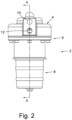
- a fuel filter 2 is comprised of a manifold 4, to which is attach a connector element 6. Reversibly connected to the connector element 6 is a filter bowl 8.
- the manifold 4 defines a fuel inlet port 10 and a fuel outlet port 12.
- the fuel inlet and outlet ports 10, 12 are provided with means (not shown) to engage with the ends of a fuel input line (not shown) and a fuel output line (not shown) respectively.
- the connector element 6 is attached to the manifold 4 by a number of bolts 14 with an annular gasket 16 between the abutting faces of the connector element 6 and manifold 4.
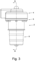
- the filter bowl 8 is adapted to reversibly engage with the connector element 6 via a helical screw thread (not shown) which is formed on the face of a portion of the radially outer face of the filter bowl element 70 and the radially inner face of connector element portion 72.
- the screwthread is dimensioned so that filter bowl element 70 may be screwed into the connector element portion 72 until the stop 76 on the filter bowl 8 abuts the edge 80 of the connector element portion 72.
- the stop 76 on the filter bowl abuts the edge 80 of the connector element portion 72 the portion of the filter bowl element 70 furthest from the filter bowl base 78 is adjacent to the annular seals 74 and a fuel tight seal is formed between the connector element portion 72 and the filter bowl element 70.
- the annular seals 74 are retained in a pair of annular grooves (not labelled) in the inner face of connector element portion 72.
- the annular seals 74 are o rings and are formed of a fluorocarbon that is suitable for high temperatures and which has good chemical resistance, for example Viton (Registered trade mark) GLT which is available from DuPont Performance Elastomers. This is also the material used in connection with other annularseals, in particular o rings, used in this embodiment of a fuel filter according to the current embodiment of the present disclosure.
- the filter bowl 8 is configured and dimensioned to substantially surround a known filter element 110.
- the filter element 110 is cylindrical and constructed to filter fuel that is flowing radially outwardly from an inlet filter chamber 92 in the inside of the cylinder of the filter element 110 to an outlet filter chamber 64 outside the filter element 110.
- the base 78 of the filter bowl 8 is configured to engage with a first end of the filter element 110.
- the engagement is a push fit of the filter element 110 onto a spindle 114.
- the push fit is sufficiently tight that fuel will not flow through the joint between the filter element and the spindle 114.
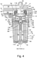
- the manifold 4 and connector element 6 define a chamber between the faces 52, 54 and 22 of the manifold 4 and face 130 and walls 56, 24, and 36 of the connector element 6. That chamber is split into second inlet chamber 20 and second outlet chamber 50.
- Second inlet chamber 20 is defined in part by a recess face 22 in the manifold 4, in part by a valve seat element 24 and wall 36 of the connector element 6, and in part by valve plug 132.
- Valve plug 132 is comprised of a valve face 134, a pressure face 136, and a cylindrical valve plug passage wall 138.
- the valve face 134 is configured to sealingly abut the valve seat face 142 of the valve seat element 24 and is biased into that abutment by a biasing means 118 which is compressed between the manifold 4 and the valve plug 132.
- the biasing means 118 is calibrated to exert a spring force that will be overcome once fuel in the second inlet chamber 20 achieves a predetermined fuel pressure.
- the valve plug 132 and valve seat element 24 collectively form a relief valve.
- valve plug passage wall 138 The face of the valve plug passage wall 138 facing inwards, towards the opposite side of the valve plug passage wall 138, defines a part of the second inlet chamber 20.
- the valve plug passage wall 138 is in a sliding fit with the recess face 22 of manifold 4 and a sliding sealing means 140, such as an o ring, creates a fuel tight seal between recess face 22 and valve plug passage wall 138.
- the manifold 4 defines an inlet passage 18 which extends from the fuel inlet port 10 to the second inlet chamber 20.
- the second inlet chamber recess face 22, chamber element 24, wall 36 define substantially cylindrical volumes and chamber element 24 is configured to be a sliding fit within the recess face 22.
- An annular seal 28, such as an o ring, is retained in an annular grove 26 in the radially outer surface of the chamber element 24 to form a fuel tight seal between the chamber element 24 and recess face 22.
- the radially innerface of the chamber element24 thus constitutes the side wall and the second end wall of the second inlet chamber is wall 36.
- the second inlet chamber 20 has a first inlet chamber aperture 30 and a second inlet aperture 32.
- the first inlet chamber aperture 30 is the mouth of the inlet passage 18 into the second inlet chamber 20 and passes through recess face 22 of the manifold 4.
- the second inlet aperture 32 is defined by the wall 36 of the connector element 6 and the face of wall 36 defining the aperture 32 includes an annular grove (not labelled) in which is retained an annular seal 34, such as an o ring.
- the second inlet aperture 32 is circular in cross section (in the plane of the wall 36 of the connector element 4) and is dimensioned so that a cylindrical conduit element 38 with a side wall 40 can pass through the aperture 32 and the side wall 40 of the conduit element is in a sliding fit with the face of the wall 36 defining the aperture 32.
- the annularseal 34 forms a fuel tight seal between the face of wall 36 defining the aperture 32 and the side wall 40 of the conduit element when the side wall 40 has a blank portion that is a portion of the side wall 40 without apertures.
- the conduit element 38 has a first closed end 42 and, extending laterally from the closed end 42 is a radially extending flange plate 44.
- the flange plate 44 defines a number of apertures 120, and has an outer edge 122.
- the flange plate 44 is so dimensioned configured that the outer edge 122 of the flange plate 44 is clear of the radially inner face of valve seat element 24 of the connector element 6.
- the flange plate 44 is biased toward the wall 36 of the connector element 6 by a biasing means 124. This biases the conduit element 38 as a whole towards the base 78 of the filter bowl 8.
- the face of the flange plate 44 facing the wall 36 has a coating of a flexible sealant (not shown). The flange plate 44 may be impelled against the wall 36 to cause the sealant to form a fuel tight seal between the flange plate 44 and the wall 36 and the fuel to cease to be able to flow through the apertures 120.
- the flange plate 44 and wall 36 thus collectively form an inlet shutoff valve.
- the sealant forms a fuel tight seal between the flange plate 44 and the wall 36 and fuel ceases to be able to flow through the apertures 120 the inlet shutoff valve in its closed configuration.
- the biasing means 124 is compressed between the wall 36 of the connector element 6 and a circumferential ridge 144 that is retained in the circumferential grove 146 in the side wall 40 of the conduit element 38.
- the conduit element 38 is of a length such that the second end 82 of the conduit element 38 abuts and sits within a cup 84 at the centre of the base 78 of the filter bowl 8.
- the abutment of second end 82 in the cup 84 has the advantage that when the filter bowl 8 is being screwed onto connection elements the cup 84 prevents any risk of the rotation of the filter bowl 8 causing the second end 82 of the conduit element 38 to move away from the centre of the filter bowl base 78 and potentially jam the conduit element 38 in a skewed position in aperture 32.
- the conduit element 38 is of such a length that when the second end 82 of the conduit element 38 is in the cup 84 sufficient of the conduit element 38 adjacent its first end 42 projects through the aperture 32 toward the manifold 4 that the first fuel apertures 46 entirely mouth into the second inlet chamber 20 as shown in Figures 4 and 5 .
- This is the inlet shutoff valve in its open configuration. This allows fuel to flow from the second inlet chamber 20 through the first fuel apertures 46 and into the conduit 86 of the conduit element 38.
- the side wall 40 of the conduit element 38 further defines a number of second fuel apertures 88 at a longitudinal position separated from the first fuel apertures 46 by a blank portion of the wall 90.
- the longitudinal dimension of the blank portion of the wall 90 is sufficient that some or all of the second fuel apertures 88 mouth into the filter inlet chamber 92 irrespective of the position of the conduit element 38 as it sits at the inlet shutoff valve open or closed configuration or at some position between those two configurations.
- the second outlet chamber 50 is in part defined by faces 52 and 54 of the manifold 4, in part by the radially outer face of chamber element24 and wall 56 of the connector element 6, and in part by the valve plug 142.
- the face 52 of the manifold 4 defines a first outlet chamber aperture 60 and the wall 56 of the connector element 6 defines a number of second outlet chamber apertures 58.
- the first outlet chamber aperture 60 is the mouth of the outlet passage 62 which extends to the fuel outlet port 12.
- the second outlet chamber apertures 58 are in communication with the outlet filter chamber 64.
- a plate element 66 In a loose sliding fit with and extending around the chamberelement24 of the connector element 6 is a plate element 66.
- the plate element 66 is dimensioned so as to overlie all of the second outlet chamber apertures 58 when the plate element 66 is in contact with the wall 56 of the connector element 6.
- the face of the plate element 66 which contacts the wall 56 is proved with a flexible seal coating (not labelled) with the result that when the plate element 66 is impelled into contact with the wall 56 a fuel tight seal is created between the plate ele ment 66 and the wall 56 and fuel cannot then pass through the second outlet chamber apertures 58.
- a biasing means 68 in the form of a compression helical spring is compressed between the face 54 of the manifold 4 and the plate element 66 and impels the plate element 66 into contact with the wall 56.
- the plate 66 and the wall 56 collectively form an outlet shutoff valve. When the plate element 66 is impelled into contact with the wall 56 and the second outlet chamber apertures 58 are sealed the plate element 66 the outlet shutoff valve is in its closed configuration.
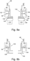
- the filter element 110 has a second end 158 onto which is attached an outlet shutoff valve engagement element 150.
- the outlet shutoff valve engagement element 150 is comprised of a plate 152 from which four engagement pegs 154 are upstanding.
- the outlet shutoff valve engagement element 150 is attached to the second end 158 of the fuel filter by an adhesive pad 156 with the upstanding pegs 154 extending away from the filter element 110.
- the wall 56 of the connector element 6 defines a number of apertures (not shown) which correspond in position to the positions of the engagement pegs 154 with the result that when the filter bowl 8 is attached to the connector element 6 while the filter element 110 is mounted on the spindle 114 the pegs 154 pass through the apertures (not shown), contact the plate element 66 and impel the plate element 66 away from the wall 56 of the connector element 6 and into the outlet shutoff valve open configuration (illustrated in Figure 8a ).
Landscapes
- Engineering & Computer Science (AREA)
- Chemical & Material Sciences (AREA)
- Chemical Kinetics & Catalysis (AREA)
- Combustion & Propulsion (AREA)
- Mechanical Engineering (AREA)
- General Engineering & Computer Science (AREA)
- Fuel-Injection Apparatus (AREA)
- Filtration Of Liquid (AREA)
Claims (14)
- Kraftstofffilter (2), der einen Verteiler (4), ein Verbindungselement (6), einen Filtertopf (8), ein Filterelement (110), ein Einlassabsperrventil (38, 36), ein Auslassabsperrventil(66, 56), eine Einlassöffnung (10), einen Einlasskanal (18), eine Auslassöffnung (12), einen Auslasskanal (62) und ein Überdruckventil (24, 132) umfasst, wobeidas Verbindungselement (6) an dem Verteiler (4) befestigt ist und der Filtertopf (8) reversibel an dem Verbindungselement (6) befestigt ist,wobei das Verbindungselement (6) und der Verteiler (4) eine Kammer definieren und die Kammer durch das Überdruckventil (24, 132) in eine zweite Einlasskammer (20) und eine zweite Auslasskammer (50) geteilt wird,wobei der Filtertopf (8) zur reversiblen Aufnahme des Filterelements (110) ausgelegt ist und so konfiguriert ist, dass, wenn das Filterelement (110) innerhalb des Filtertopfs (8) angeordnet ist und der Filtertopf (8) an dem Verbindungselement (6) angebracht ist, das Filterelement (110) den durch das Verbindungselement und den Filtertopf (8) definierten Raum in eine Einlassfilterkammer (92) und eine Auslassfilterkammer (64) aufteilt,wobei die Einlassöffnung (10) in den Verteiler (4) integriert ist und die Einlassöffnung (10) und die Einlassfilterkammer (92) über den Einlasskanal (18) und die zweite Einlasskammer (20) in Fluidverbindung stehen,wobei die Auslassöffnung (12) in den Verteiler (4) integriert ist und die Auslassöffnung (12) und die Auslassfilterkammer (64) über den Auslasskanal (62) und die zweite Auslasskammer (50) in Fluidverbindung stehen,wobei das Einlassabsperrventil (38, 36) durch ein Vorspannmittel (124) in eine geschlossene Konfiguration vorgespannt ist, die verhindert, dass Kraftstoff entlang des Einlasskanals (18) fließt, wenn der Filtertopf (8) nicht mit dem Verbindungselement (6) verbunden ist,wobei die Verbindung des Filtertopfs (8) mit dem Verbindungselement (6) bewirkt, dass das Einlassabsperrventil (38, 36) in eine offene Konfiguration gedrängt wird, die es dem Kraftstoff ermöglicht, entlang des Einlasskanals (18) zu fließen,wobei das Auslassabsperrventil (66, 56) durch ein Vorspannmittel (68) in eine geschlossene Konfiguration vorgespannt wird, die verhindert, dass der Kraftstoff entlang des Auslasskanals (62) fließt,wobei das Auslassabsperrventil (66, 56) dazu konfiguriert ist, sich in eine geschlossene Konfiguration zu bewegen, die verhindert, dass Kraftstoff entlang des Auslasskanals (62) fließt, wenn der Filtertopf (8) mit einem darin befindlichen Filterelement (110) nicht mit dem Verbindungselement (6) verbunden ist oder sich kein Filterelement (110) im Filtertopf (8) befindet, undwobei die Verbindung des Filtertopfs (8) mit einem darin befindlichen Filterelement (110) mit dem Verbindungselement (6) bewirkt, dass das Auslassabsperrventil (66, 56) in eine offene Konfiguration gedrängt wird, die dem Kraftstoff ermöglicht, entlang des Auslasskanals (62) zu fließen,wobei das Überdruckventil (24, 132) durch ein Vorspannmittel (118) in eine geschlossene Konfiguration vorgespannt ist, sodass Kraftstoff, der zwischen dem Einlasskanal (18) und dem Auslasskanal (62) fließt, durch das Filterelement (110) treten muss, undwobei die Bewegung des Überdruckventils (24, 132) in eine offene Konfiguration ermöglicht, dass Kraftstoff über das Überdruckventil (24, 132) zwischen dem Einlasskanal (18) und dem Auslasskanal (62) fließt, ohne dass der Kraftstoff durch das Filterelement (110) tritt.
- Kraftstofffilter (2) nach Anspruch 1, wobei das Drängen des Einlassabsperrventils (38, 36) und des Auslassabsperrventils (66, 56) in ihre offene Konfiguration nach Beginn der Verbindung des Kraftstofffiltertopfs (8) mit dem Filterelement (110) innerhalb des Verbindungselements (6) und bevor der Kraftstofffiltertopf (8) vollständig mit dem Verbindungselement (6) verbunden ist beginnt.
- Filterventil nach Anspruch 1 oder 2, wobei die zweite Einlasskammer (20) durch den Verteiler (4), das Verbindungselement (6) und einen Abschnitt des Überdruckventils (24, 132) definiert ist und der Abschnitt der zweiten Einlasskammer (20), der die durch den Abschnitt des Verbindungselements (6) definiert ist, eine oder mehrere Seitenwände und eine zweite Endwand (36) aufweist,wobei der Abschnitt der zweiten Einlasskammer (20), der durch den Abschnitt des Verbindungselements (6) definiert ist, einen Querschnitt in einer Ebene parallel zur zweiten Endwand (36) aufweist, der an allen Positionen in diesem Abschnitt gleich ist,wobei der Verteiler (4) und das Verbindungselement (6), die die zweite Einlasskammer (20) definieren, auch eine erste bzw. zweite Einlasskammeröffnung (30, 32) definieren, wobei die erste Einlasskammeröffnung (30) eine Mündung des Abschnitts des Einlasskanals (18) ist, der sich von der Kraftstoffeinlassöffnung (10) erstreckt,wobei die zweite Einlasskammeröffnung (32) durch die zweite Endwand (36) verläuft und mindestens eine Gleitdichtung (34) sich um den Rand oder die Innenfläche der zweiten Einlasskammeröffnung (32) erstreckt,wobei das Einlassabsperrventil (38, 36) ein sich in Längsrichtung erstreckendes Leitungselement (38) umfasst, wobei das Leitungselement (38) dazu konfiguriert ist, sich durch die zweite Einlasskammeröffnung (32) in einem kraftstoffdichten Gleiteingriff mit der Gleitdichtung (34) zu erstrecken,wobei das Leitungselement (38) ein erstes Flanschende (42), ein zweites Ende (82) und eine oder mehrere Seitenwände (40) umfasst,wobei das erste Ende (42) des Leitungselements (38) geschlossen ist,wobei der Flansch (44) des ersten Endes (42) des Leitungselements (38) ein Flanschelement (44) umfasst, das sich seitlich (relativ zur Längsachse des Leitungselements (38)) von dem ersten Ende (42) des Leitungselements (38) erstreckt und einen äußeren Rand (122) aufweist, der von dem Leitungselement (38) beabstandet ist,wobei das Flanschelement (44) mindestens eine Öffnung (120) definiert, die durch den Flansch (44) verläuft,wobei das Flanschelement (44) so bemessen und konfiguriert ist, dass sein äußerer Rand (122) in gleitendem Kontakt mit der oder jeder Seitenwand der zweiten Einlasskammer (20) steht,wobei die eine oder die mehreren Seitenwände (40) des Leitungselements (38) sich zwischen dem ersten und dem zweiten Ende (42, 82) erstrecken und mindestens eine Seitenwand (40) des Leitungselements (38) mindestens eine erste Kraftstofföffnung (46) definiert, die durch die Seitenwand (40) in einer Position neben oder nahe dem ersten Ende (42) verläuft,wobei das Leitungselement (38) durch ein erstes Vorspannmittel (124) vorgespannt wird, um sich in eine Position zu bewegen, in der das Flanschelement (44) des Leitungselements gegen die zweite Endwand (36) der zweiten Einlasskammer (20) gedrängt wird,und wobei ein Dichtungsmittel, das dazu ausgelegt ist, jede der Flanschöffnungen 122 abzudichten, wenn das Flanschelement (44) des Leitungselements (38) gegen die zweite Endwand (36) der zweiten Einlasskammer (20) gedrängt wird, an einer oder beiden von der der zweiten Endwand (36) der zweiten Einlasskammer (20) zugewandten Seite der Flanschplatte (44) und der der Flanschplatte (44) zugewandten Seite der zweiten Endwand (36) der zweiten Einlasskammer (20) angebracht ist.
- Filterventil nach Anspruch 1 oder 2, wobei die zweite Einlasskammer (20) durch den Verteiler (4), das Verbindungselement (6) und einen Abschnitt des Überdruckventils (24, 132) definiert ist und der Abschnitt der zweiten Einlasskammer (20), der durch den Abschnitt des Verbindungselements (6) definiert ist, eine oder mehrere Seitenwände und eine zweite Endwand aufweist,wobei der Abschnitt der zweiten Einlasskammer (20), der durch den Abschnitt des Verbindungselements (6) definiert ist, einen Querschnitt in einer Ebene parallel zu der zweiten Endwand aufweist, der an allen Positionen in diesem Abschnitt gleich ist,wobei der Verteiler (4) und das Verbindungselement (6), die die zweite Einlasskammer (20) definieren, auch eine erste bzw. eine zweite Einlasskammeröffnung (30, 32) definieren, wobei die erste Einlasskammeröffnung (30) eine Mündung des Abschnitts des Einlasskanals ist (18), der sich von der Kraftstoffeinlassöffnung (10) erstreckt,wobei die zweite Einlasskammeröffnung (32) durch die zweite Endwand (36) verläuft und sich mindestens ein Gleitdichtungsmittel (34) um den Rand oder die Innenfläche der zweiten Einlasskammeröffnung (32) erstreckt,wobei das Einlassabsperrventil (38, 36) ein sich in Längsrichtung erstreckendes Leitungselement (38) umfasst,wobei das Leitungselement (38) dazu konfiguriert ist, sich durch die zweite Einlasskammeröffnung (32) in einem kraftstoffdichten Gleiteingriff mit dem Gleitdichtungsmittel (34) zu erstrecken, wobei das Leitungselement (38) ein erstes Ende (42), ein zweites Ende (82) und ein oder mehrere Seitenwände (40) umfasst,wobei das erste Ende (42) des Leitungselements (38) geschlossen und mit einem Flansch (44) bereitgestellt ist, der sich seitlich (relativ zur Längsachse des Leitungselements (38)) von dem ersten Ende (42) des Leitungselements (38) erstreckt,wobei die eine oder die mehreren Seitenwände (40) des Leitungselements (38) sich zwischen dem ersten und dem zweiten Ende (42, 82) erstrecken, wobei mindestens eine Seitenwand (40) des Leitungselements (38) mindestens eine erste Kraftstofföffnung (46) definiert, die durch die Seitenwand (40) an einer Position neben oder nahe dem ersten Ende (42) verläuft, wobei das Leitungselement (38) durch ein erstes Vorspannmittel (124) vorgespannt ist, um sich in eine Position zu bewegen, in der der Flansch (44) des Leitungselements (38) gegen die zweite Endwand (36) der zweiten Einlasskammer (20) gedrängt wird, und wobei ein Dichtungsmittel (34) bereitgestellt ist, das dazu ausgelegt ist, die zweite Einlasskammeröffnung (32) abzudichten, wenn das Flanschelement (44) des Leitungselements (38) gegen die zweite Endwand (36) der zweiten Einlasskammer (20) gedrängt wird.
- Kraftstofffilter (2) nach Anspruch 3 oder 4, wobei das Leitungselement (38) ferner eine oder mehrere zweite Kraftstofföffnungen (88) umfasst, die durch eine oder mehrere der Seitenwände (40) des Leitungselements (38) definiert sind, wobei die eine oder die mehreren zweiten Kraftstofföffnungen (88) in Längsrichtung zwischen der einen oder den mehreren ersten Kraftstofföffnungen (46) und dem zweiten Ende (82) des Leitungselements (38) angeordnet sind,
und wobei das Leitungselement (38) so bemessen und konfiguriert ist, dass, wenn der Filtertopf (8) vollständig am Verbindungselement (6) angebracht ist, das zweite Ende des Leitungselements (38) an einem Abschnitt des Filtertopfs (8) anliegt, die Öffnungen (120) im Flansch des Leitungselements (38) nicht abgedichtet sind, die ersten Kraftstofföffnungen (46) des Leitungselements (38) in die zweite Einlasskammer (20) münden und die zweiten Kraftstofföffnungen (88) des Leitungselements (38) in die Einlassfilterkammer (92) münden. - Kraftstofffilter (2) nach einem der Ansprüche 3 bis 5, der ferner eine Zwischenstruktur umfasst, wobei das zweite Ende (82) des Leitungselements (38) über die Zwischenstruktur an einem Teil des Filtertopfs (8) anliegt, wenn der Filtertopf (8) vollständig an dem Verbindungselement (6) angebracht ist, und wobei die Zwischenstruktur so konfiguriert und bemessen ist, dass das Vorspannmittel (124) die Zwischenstruktur verschieben und das Leitungselement (38) in die geschlossene Konfiguration bewegen kann, wenn der Filtertopf (8) von dem Verbindungselement (6) gelöst wird.
- Kraftstofffilter (2) nach einem der Ansprüche 3 bis 6, wobei der Abschnitt des Verteilers (4), der die zweite Auslasskammer (50) teilweise definiert, eine erste Auslasskammeröffnung (60) definiert,wobei der Abschnitt des Verbindungselements (6), der teilweise die zweite Auslasskammer (50) definiert, auch eine oder mehrere zweite Auslasskammeröffnungen (58) definiert,wobei die erste Auslasskammeröffnung (60) eine Mündung des Abschnitts des Auslasskanals (62) ist, der sich von der Kraftstoffauslassöffnung (12) erstreckt,wobei die oder jede zweite Auslasskammeröffnung (58) in Fluidverbindung mit der Auslassfilterkammer (64) steht,wobei das Auslassabsperrventil (66, 56) ein Öffnungsverschlusselement (66) umfasst, wobei das Öffnungsverschlusselement (66) dazu konfiguriert ist, über allen zweiten Auslasskammeröffnungen (58) zu liegen und zwischen einer geschlossenen Konfiguration, in der das Öffnungsverschlusselement (66) alle der zweiten Auslasskammeröffnungen abdichtet, und einer offenen Konfiguration, die von den zweiten Auslasskammeröffnungen (58) beabstandet ist, beweglich ist, und wobei das Öffnungsverschlusselement (66) durch das Vorspannmittel (68) in die geschlossene Konfiguration vorgespannt ist.
- Kraftstofffilter (2) nach Anspruch 7, wobei der Kraftstofffilter (2) eine oder mehrere Auslasszwischenstrukturen (150) umfasst,wobei jede Auslasszwischenstruktur (150) so bemessen und konfiguriert ist, dass sie einen Abschnitt des Filterelements (110) zumindest dann berührt, wenn der Filtertopf (8) vollständig an dem Verbindungselement (6) angebracht ist und sich das Filterelement (110) innerhalb des Filtertopfs (8) befindet,wobei jede Auslasszwischenstruktur (150) das Öffnungsverschlussmittel (66) in seine geöffnete Konfiguration drängt, wenn der Filtertopf (8) vollständig am Verbindungselement (6) angebracht ist und das Filterelement (110) korrekt in dem Filtertopf (8) angeordnet ist, undwobei die eine oder die mehreren Auslasszwischenstrukturen (150) es dem Vorspannmittel (68) ermöglichen, jede der Auslasszwischenstrukturen (150) zu verschieben und das Öffnungsverschlussmittel (66) in die geschlossene Konfiguration zu bewegen, wenn der Filtertopf (8) und das Filterelement (110) von dem Verbindungselement (6) gelöst sind.
- Kraftstofffilter (2) nach einem der Ansprüche 1 bis 8, wobei das Überdruckventil (24, 132) einen Ventilsitz (24) und einen Ventilkegel (142) aufweist, wobei das Vorspannmittel (118) den Ventilkegel (142) gegen den Ventilsitz (24) vorspannt und der Ventilkegel (142) in eine vom Ventilsitz (24) beabstandete Position gedrängt werden kann.
- Kraftstofffilter (2) nach Anspruch 9, wobei der Ventilkegel (142) eine kegelstumpfförmige Ventilfläche (134) aufweist und der Ventilsitz (24) entsprechend konfiguriert ist.
- Kraftstofffilter (2) nach Anspruch 9 oder 10, wobei der Ventilkegel (142) eine Ventilfläche (134), eine Druckfläche (136) und eine oder mehrere Wände (138) umfasst, die einen Ventilkegelkanal definieren,wobei die Ventilfläche (134) dazu ausgelegt ist, eine Dichtung mit dem Ventilsitz (24) zu bilden,wobei die Ventilfläche (134) sich um die Außenseite der Wand oder Wände (138) erstreckt, die den Ventilkegelkanal definieren, wobei die Fläche der Wand oder Wände (138), die in den Ventilkegelkanal weisen, teilweise die zweite Einlasskammer (20) definieren,wobei die Fläche der Wand oder der Wände (138), die von dem Ventilkegelkanal abgewandt ist, teilweise die zweite Auslasskammer (50) definiert, undwobei ein erstes Ende der Wand oder der Wände (138) durch die Druckfläche (136) mit der Ventilfläche (134) verbunden ist.
- Kraftstofffilter (2) nach Anspruch 11, wobei die Ventilfläche (134) eine kegelstumpfförmige Konfiguration aufweist und die Druckfläche (136) an den Rand mit kleinerem Durchmesser der kegelstumpfförmigen Ventilfläche (134) anschließt.
- Kraftstofffilter (2) nach einem der Ansprüche 1 bis 12, wobei mindestens eines der Vorspannungsmittel (68, 118, 124) eine Druckfeder ist.
- Verfahren zum Zuführen von Kraftstoff zu einer Brennkammer eines Gasturbinentriebwerks, umfassend Leiten des Kraftstoffs durch einen Kraftstofffilter (2) nach einem der Ansprüche 1 bis 13 vor Einführung des Kraftstoffs in die Brennkammer.
Applications Claiming Priority (1)
| Application Number | Priority Date | Filing Date | Title |
|---|---|---|---|
| PL43338920 | 2020-03-30 |
Publications (2)
| Publication Number | Publication Date |
|---|---|
| EP3907397A1 EP3907397A1 (de) | 2021-11-10 |
| EP3907397B1 true EP3907397B1 (de) | 2023-06-07 |
Family
ID=74947256
Family Applications (1)
| Application Number | Title | Priority Date | Filing Date |
|---|---|---|---|
| EP21163267.4A Active EP3907397B1 (de) | 2020-03-30 | 2021-03-17 | Kraftstofffilteranordnung |
Country Status (2)
| Country | Link |
|---|---|
| US (1) | US11717776B2 (de) |
| EP (1) | EP3907397B1 (de) |
Families Citing this family (3)
| Publication number | Priority date | Publication date | Assignee | Title |
|---|---|---|---|---|
| EP3907396B1 (de) | 2020-03-30 | 2023-06-07 | Hamilton Sundstrand Corporation | Kraftstofffilteranordnung |
| EP3907398B1 (de) | 2020-03-30 | 2023-05-03 | Hamilton Sundstrand Corporation | Kraftstofffilteranordnung |
| EP3904667B1 (de) | 2020-04-28 | 2024-08-14 | Hamilton Sundstrand Corporation | Kraftstofffilteranordnung |
Family Cites Families (35)
| Publication number | Priority date | Publication date | Assignee | Title |
|---|---|---|---|---|
| US3235085A (en) | 1962-01-08 | 1966-02-15 | Wix Corp | Filter unit having dual purpose valve assembly |
| US4053410A (en) | 1975-09-10 | 1977-10-11 | Caterpillar Tractor Co. | Filter assembly with modulating bypass valve |
| US4127484A (en) | 1977-09-09 | 1978-11-28 | Purolator, Inc. | Filter relief valve assembly |
| GB2120568B (en) | 1982-05-25 | 1985-12-24 | Lucas Ind Plc | Fuel filter |
| US4617116A (en) | 1984-05-04 | 1986-10-14 | Ford Motor Company | Automotive type fuel feed system |
| US4818397A (en) | 1986-12-22 | 1989-04-04 | Sundstrand Corporation | Shut-off valve seal |
| IT1205804B (it) | 1987-04-13 | 1989-03-31 | Ital Idee Srl | Filtro multiplo per olio lubrificante per motori a combustione interna con organo di controllo del grado di intasamento della superficie filtrante |
| US4876857A (en) | 1988-08-15 | 1989-10-31 | Allied-Signal Inc. | Shut off/pressure regulating valve for turbine engine |
| DE4310492A1 (de) | 1993-03-31 | 1994-10-06 | Hydac Filtertechnik Gmbh | Filtervorrichtung mit Keyportanschluß |
| US6113781A (en) | 1993-09-15 | 2000-09-05 | Parker-Hannifin Corporation | Fuel filter with dual flow |
| US6068762A (en) | 1995-09-29 | 2000-05-30 | Parker-Hannifin Corporation | Reusable oil filter assembly |
| US6068763A (en) | 1997-09-12 | 2000-05-30 | Purolator Products Company | Spin-on oil filter with replaceable element |
| US5881699A (en) | 1997-12-22 | 1999-03-16 | Ford Global Technologies, Inc. | Diesel fuel recirculating manifold |
| DE29915844U1 (de) | 1999-09-09 | 2001-01-25 | Ing. Walter Hengst GmbH & Co KG, 48147 Münster | Filter mit Ventil-Kombinationsbauteil |
| US6555000B2 (en) | 1999-12-03 | 2003-04-29 | Parker-Hannifin Corporation | Fuel filter with bypass valve |
| US20030127384A1 (en) | 2002-01-09 | 2003-07-10 | Desh Kapur | Filter module for aircraft lubrication systems |
| DE10213939A1 (de) | 2002-03-28 | 2003-10-09 | Mann & Hummel Filter | Ventilanordnung, insbesondere für den Schmierölkreislauf einer Brennkraftmaschine |
| DE10315052A1 (de) * | 2002-04-03 | 2003-12-11 | Kyosan Denki Kk | Kraftstoffzuführsystem |
| KR20070011489A (ko) | 2004-04-13 | 2007-01-24 | 도날드슨 캄파니 인코포레이티드 | 액체 여과용 필터 카트리지 |
| DE102004024466A1 (de) | 2004-05-14 | 2005-12-08 | Mann + Hummel Gmbh | Kraftstoffmodul |
| US7744758B2 (en) | 2005-02-15 | 2010-06-29 | Mann + Hummel Gmbh | Liquid filter |
| US8316880B2 (en) | 2009-05-08 | 2012-11-27 | Hamilton Sundstrand Corporation | Oil filter bypass valve assembly for a generator |
| ITMI20111315A1 (it) * | 2011-07-15 | 2013-01-16 | Acl S R L | Apparecchiatura filtrante |
| FR2979387B1 (fr) * | 2011-08-31 | 2017-02-10 | Snecma | Circuit de carburant dans une turbomachine |
| US9453462B2 (en) | 2012-08-31 | 2016-09-27 | Hamilton Sundstrand Corporation | Filter bypass valve |
| DE202014104029U1 (de) | 2014-08-28 | 2014-10-20 | Hengst Se & Co. Kg | Filter, der an einem Anschlussflansch anbaubar ist, und Filtereinsatz |
| US9441598B2 (en) | 2013-11-08 | 2016-09-13 | Honeywell International Inc. | Aircraft fuel filter impending and actual bypass indication system |
| DE102013223352A1 (de) | 2013-11-15 | 2015-05-21 | Mahle International Gmbh | Flüssigkeitsfilter |
| US10024239B2 (en) | 2015-07-22 | 2018-07-17 | Pratt & Whitney Canada Corp. | Fuel filter and bypass valve arrangement |
| DE102018221261A1 (de) | 2018-12-07 | 2020-06-10 | Mahle International Gmbh | Baugruppe für eine Filtereinrichtung sowie Filtereinrichtung mit einer solchen Baugruppe |
| DE102019109388A1 (de) | 2019-04-10 | 2020-10-15 | Mann+Hummel Gmbh | Rezirkulationsmodul und Kraftstoffvorfiltereinheit |
| EP3907396B1 (de) | 2020-03-30 | 2023-06-07 | Hamilton Sundstrand Corporation | Kraftstofffilteranordnung |
| EP3907398B1 (de) * | 2020-03-30 | 2023-05-03 | Hamilton Sundstrand Corporation | Kraftstofffilteranordnung |
| EP3904667B1 (de) * | 2020-04-28 | 2024-08-14 | Hamilton Sundstrand Corporation | Kraftstofffilteranordnung |
| EP4015814B1 (de) | 2020-12-17 | 2024-08-14 | Collins Engine Nozzles, Inc. | Kraftstofffilteranordnung |
-
2021
- 2021-03-17 EP EP21163267.4A patent/EP3907397B1/de active Active
- 2021-03-24 US US17/210,721 patent/US11717776B2/en active Active
Also Published As
| Publication number | Publication date |
|---|---|
| EP3907397A1 (de) | 2021-11-10 |
| US11717776B2 (en) | 2023-08-08 |
| US20210299599A1 (en) | 2021-09-30 |
Similar Documents
| Publication | Publication Date | Title |
|---|---|---|
| EP3907396B1 (de) | Kraftstofffilteranordnung | |
| EP3904667B1 (de) | Kraftstofffilteranordnung | |
| EP4015814A1 (de) | Kraftstofffilteranordnung | |
| EP3907397B1 (de) | Kraftstofffilteranordnung | |
| EP3907398B1 (de) | Kraftstofffilteranordnung | |
| US6050081A (en) | Air purging fuel valve for turbine engine | |
| US4537384A (en) | In-line check valve having combined downstream poppet support and flow control elements | |
| EP0759122B1 (de) | Kraftstoffleitungsanlage ohne rücklaufleitung mit vakuumgesteuertem kraftstoffdruck | |
| EP0150619B1 (de) | Ventil für die Verteilung der Strömung | |
| CN114729601B (zh) | 具有减小的流量容差的燃料喷嘴 | |
| US12233359B2 (en) | Filter cartridge with valve activation feature | |
| US7389791B2 (en) | Backflow preventer | |
| CN117167530B (zh) | 可更换的压力控制阀 | |
| US7322373B2 (en) | High accuracy low leakage valve for high pressure applications | |
| JPS60231073A (ja) | 高圧力流体制御弁 | |
| CN105142751A (zh) | 球形接触球接头型泄流滑阀 | |
| US11022226B2 (en) | Microfluidic valve | |
| CN102754041B (zh) | 压力调节阀 | |
| US20050029172A1 (en) | Filter head and burner system incorporating same | |
| KR101657174B1 (ko) | 안전밸브를 구비하는 체크밸브 | |
| CN211820762U (zh) | 一种高可靠性反向闭合阀门 | |
| US10190498B1 (en) | Valve with valve member cooling | |
| JP2026018135A (ja) | 遮断弁 | |
| KR101647939B1 (ko) | 안전밸브의 감압장치 |
Legal Events
| Date | Code | Title | Description |
|---|---|---|---|
| PUAI | Public reference made under article 153(3) epc to a published international application that has entered the european phase |
Free format text: ORIGINAL CODE: 0009012 |
|
| STAA | Information on the status of an ep patent application or granted ep patent |
Free format text: STATUS: THE APPLICATION HAS BEEN PUBLISHED |
|
| AK | Designated contracting states |
Kind code of ref document: A1 Designated state(s): AL AT BE BG CH CY CZ DE DK EE ES FI FR GB GR HR HU IE IS IT LI LT LU LV MC MK MT NL NO PL PT RO RS SE SI SK SM TR |
|
| B565 | Issuance of search results under rule 164(2) epc |
Effective date: 20211008 |
|
| STAA | Information on the status of an ep patent application or granted ep patent |
Free format text: STATUS: REQUEST FOR EXAMINATION WAS MADE |
|
| 17P | Request for examination filed |
Effective date: 20220330 |
|
| RBV | Designated contracting states (corrected) |
Designated state(s): AL AT BE BG CH CY CZ DE DK EE ES FI FR GB GR HR HU IE IS IT LI LT LU LV MC MK MT NL NO PL PT RO RS SE SI SK SM TR |
|
| GRAP | Despatch of communication of intention to grant a patent |
Free format text: ORIGINAL CODE: EPIDOSNIGR1 |
|
| STAA | Information on the status of an ep patent application or granted ep patent |
Free format text: STATUS: GRANT OF PATENT IS INTENDED |
|
| INTG | Intention to grant announced |
Effective date: 20221221 |
|
| GRAS | Grant fee paid |
Free format text: ORIGINAL CODE: EPIDOSNIGR3 |
|
| GRAA | (expected) grant |
Free format text: ORIGINAL CODE: 0009210 |
|
| STAA | Information on the status of an ep patent application or granted ep patent |
Free format text: STATUS: THE PATENT HAS BEEN GRANTED |
|
| AK | Designated contracting states |
Kind code of ref document: B1 Designated state(s): AL AT BE BG CH CY CZ DE DK EE ES FI FR GB GR HR HU IE IS IT LI LT LU LV MC MK MT NL NO PL PT RO RS SE SI SK SM TR |
|
| REG | Reference to a national code |
Ref country code: GB Ref legal event code: FG4D |
|
| REG | Reference to a national code |
Ref country code: CH Ref legal event code: EP Ref country code: AT Ref legal event code: REF Ref document number: 1575765 Country of ref document: AT Kind code of ref document: T Effective date: 20230615 |
|
| REG | Reference to a national code |
Ref country code: DE Ref legal event code: R096 Ref document number: 602021002635 Country of ref document: DE |
|
| REG | Reference to a national code |
Ref country code: LT Ref legal event code: MG9D |
|
| REG | Reference to a national code |
Ref country code: NL Ref legal event code: MP Effective date: 20230607 |
|
| PG25 | Lapsed in a contracting state [announced via postgrant information from national office to epo] |
Ref country code: SE Free format text: LAPSE BECAUSE OF FAILURE TO SUBMIT A TRANSLATION OF THE DESCRIPTION OR TO PAY THE FEE WITHIN THE PRESCRIBED TIME-LIMIT Effective date: 20230607 Ref country code: NO Free format text: LAPSE BECAUSE OF FAILURE TO SUBMIT A TRANSLATION OF THE DESCRIPTION OR TO PAY THE FEE WITHIN THE PRESCRIBED TIME-LIMIT Effective date: 20230907 Ref country code: ES Free format text: LAPSE BECAUSE OF FAILURE TO SUBMIT A TRANSLATION OF THE DESCRIPTION OR TO PAY THE FEE WITHIN THE PRESCRIBED TIME-LIMIT Effective date: 20230607 |
|
| REG | Reference to a national code |
Ref country code: AT Ref legal event code: MK05 Ref document number: 1575765 Country of ref document: AT Kind code of ref document: T Effective date: 20230607 |
|
| PG25 | Lapsed in a contracting state [announced via postgrant information from national office to epo] |
Ref country code: RS Free format text: LAPSE BECAUSE OF FAILURE TO SUBMIT A TRANSLATION OF THE DESCRIPTION OR TO PAY THE FEE WITHIN THE PRESCRIBED TIME-LIMIT Effective date: 20230607 Ref country code: NL Free format text: LAPSE BECAUSE OF FAILURE TO SUBMIT A TRANSLATION OF THE DESCRIPTION OR TO PAY THE FEE WITHIN THE PRESCRIBED TIME-LIMIT Effective date: 20230607 Ref country code: LV Free format text: LAPSE BECAUSE OF FAILURE TO SUBMIT A TRANSLATION OF THE DESCRIPTION OR TO PAY THE FEE WITHIN THE PRESCRIBED TIME-LIMIT Effective date: 20230607 Ref country code: LT Free format text: LAPSE BECAUSE OF FAILURE TO SUBMIT A TRANSLATION OF THE DESCRIPTION OR TO PAY THE FEE WITHIN THE PRESCRIBED TIME-LIMIT Effective date: 20230607 Ref country code: HR Free format text: LAPSE BECAUSE OF FAILURE TO SUBMIT A TRANSLATION OF THE DESCRIPTION OR TO PAY THE FEE WITHIN THE PRESCRIBED TIME-LIMIT Effective date: 20230607 Ref country code: GR Free format text: LAPSE BECAUSE OF FAILURE TO SUBMIT A TRANSLATION OF THE DESCRIPTION OR TO PAY THE FEE WITHIN THE PRESCRIBED TIME-LIMIT Effective date: 20230908 |
|
| PG25 | Lapsed in a contracting state [announced via postgrant information from national office to epo] |
Ref country code: FI Free format text: LAPSE BECAUSE OF FAILURE TO SUBMIT A TRANSLATION OF THE DESCRIPTION OR TO PAY THE FEE WITHIN THE PRESCRIBED TIME-LIMIT Effective date: 20230607 |
|
| PG25 | Lapsed in a contracting state [announced via postgrant information from national office to epo] |
Ref country code: SK Free format text: LAPSE BECAUSE OF FAILURE TO SUBMIT A TRANSLATION OF THE DESCRIPTION OR TO PAY THE FEE WITHIN THE PRESCRIBED TIME-LIMIT Effective date: 20230607 |
|
| PG25 | Lapsed in a contracting state [announced via postgrant information from national office to epo] |
Ref country code: IS Free format text: LAPSE BECAUSE OF FAILURE TO SUBMIT A TRANSLATION OF THE DESCRIPTION OR TO PAY THE FEE WITHIN THE PRESCRIBED TIME-LIMIT Effective date: 20231007 |
|
| PG25 | Lapsed in a contracting state [announced via postgrant information from national office to epo] |
Ref country code: SM Free format text: LAPSE BECAUSE OF FAILURE TO SUBMIT A TRANSLATION OF THE DESCRIPTION OR TO PAY THE FEE WITHIN THE PRESCRIBED TIME-LIMIT Effective date: 20230607 Ref country code: SK Free format text: LAPSE BECAUSE OF FAILURE TO SUBMIT A TRANSLATION OF THE DESCRIPTION OR TO PAY THE FEE WITHIN THE PRESCRIBED TIME-LIMIT Effective date: 20230607 Ref country code: RO Free format text: LAPSE BECAUSE OF FAILURE TO SUBMIT A TRANSLATION OF THE DESCRIPTION OR TO PAY THE FEE WITHIN THE PRESCRIBED TIME-LIMIT Effective date: 20230607 Ref country code: PT Free format text: LAPSE BECAUSE OF FAILURE TO SUBMIT A TRANSLATION OF THE DESCRIPTION OR TO PAY THE FEE WITHIN THE PRESCRIBED TIME-LIMIT Effective date: 20231009 Ref country code: IS Free format text: LAPSE BECAUSE OF FAILURE TO SUBMIT A TRANSLATION OF THE DESCRIPTION OR TO PAY THE FEE WITHIN THE PRESCRIBED TIME-LIMIT Effective date: 20231007 Ref country code: EE Free format text: LAPSE BECAUSE OF FAILURE TO SUBMIT A TRANSLATION OF THE DESCRIPTION OR TO PAY THE FEE WITHIN THE PRESCRIBED TIME-LIMIT Effective date: 20230607 Ref country code: CZ Free format text: LAPSE BECAUSE OF FAILURE TO SUBMIT A TRANSLATION OF THE DESCRIPTION OR TO PAY THE FEE WITHIN THE PRESCRIBED TIME-LIMIT Effective date: 20230607 Ref country code: AT Free format text: LAPSE BECAUSE OF FAILURE TO SUBMIT A TRANSLATION OF THE DESCRIPTION OR TO PAY THE FEE WITHIN THE PRESCRIBED TIME-LIMIT Effective date: 20230607 |
|
| PG25 | Lapsed in a contracting state [announced via postgrant information from national office to epo] |
Ref country code: PL Free format text: LAPSE BECAUSE OF FAILURE TO SUBMIT A TRANSLATION OF THE DESCRIPTION OR TO PAY THE FEE WITHIN THE PRESCRIBED TIME-LIMIT Effective date: 20230607 |
|
| REG | Reference to a national code |
Ref country code: DE Ref legal event code: R097 Ref document number: 602021002635 Country of ref document: DE |
|
| PLBE | No opposition filed within time limit |
Free format text: ORIGINAL CODE: 0009261 |
|
| STAA | Information on the status of an ep patent application or granted ep patent |
Free format text: STATUS: NO OPPOSITION FILED WITHIN TIME LIMIT |
|
| PG25 | Lapsed in a contracting state [announced via postgrant information from national office to epo] |
Ref country code: DK Free format text: LAPSE BECAUSE OF FAILURE TO SUBMIT A TRANSLATION OF THE DESCRIPTION OR TO PAY THE FEE WITHIN THE PRESCRIBED TIME-LIMIT Effective date: 20230607 |
|
| PG25 | Lapsed in a contracting state [announced via postgrant information from national office to epo] |
Ref country code: SI Free format text: LAPSE BECAUSE OF FAILURE TO SUBMIT A TRANSLATION OF THE DESCRIPTION OR TO PAY THE FEE WITHIN THE PRESCRIBED TIME-LIMIT Effective date: 20230607 |
|
| 26N | No opposition filed |
Effective date: 20240308 |
|
| PG25 | Lapsed in a contracting state [announced via postgrant information from national office to epo] |
Ref country code: SI Free format text: LAPSE BECAUSE OF FAILURE TO SUBMIT A TRANSLATION OF THE DESCRIPTION OR TO PAY THE FEE WITHIN THE PRESCRIBED TIME-LIMIT Effective date: 20230607 Ref country code: IT Free format text: LAPSE BECAUSE OF FAILURE TO SUBMIT A TRANSLATION OF THE DESCRIPTION OR TO PAY THE FEE WITHIN THE PRESCRIBED TIME-LIMIT Effective date: 20230607 |
|
| REG | Reference to a national code |
Ref country code: CH Ref legal event code: PL |
|
| PG25 | Lapsed in a contracting state [announced via postgrant information from national office to epo] |
Ref country code: BG Free format text: LAPSE BECAUSE OF FAILURE TO SUBMIT A TRANSLATION OF THE DESCRIPTION OR TO PAY THE FEE WITHIN THE PRESCRIBED TIME-LIMIT Effective date: 20230607 |
|
| PG25 | Lapsed in a contracting state [announced via postgrant information from national office to epo] |
Ref country code: LU Free format text: LAPSE BECAUSE OF NON-PAYMENT OF DUE FEES Effective date: 20240317 |
|
| PG25 | Lapsed in a contracting state [announced via postgrant information from national office to epo] |
Ref country code: MC Free format text: LAPSE BECAUSE OF FAILURE TO SUBMIT A TRANSLATION OF THE DESCRIPTION OR TO PAY THE FEE WITHIN THE PRESCRIBED TIME-LIMIT Effective date: 20230607 |
|
| PG25 | Lapsed in a contracting state [announced via postgrant information from national office to epo] |
Ref country code: MC Free format text: LAPSE BECAUSE OF FAILURE TO SUBMIT A TRANSLATION OF THE DESCRIPTION OR TO PAY THE FEE WITHIN THE PRESCRIBED TIME-LIMIT Effective date: 20230607 Ref country code: LU Free format text: LAPSE BECAUSE OF NON-PAYMENT OF DUE FEES Effective date: 20240317 Ref country code: BG Free format text: LAPSE BECAUSE OF FAILURE TO SUBMIT A TRANSLATION OF THE DESCRIPTION OR TO PAY THE FEE WITHIN THE PRESCRIBED TIME-LIMIT Effective date: 20230607 |
|
| REG | Reference to a national code |
Ref country code: BE Ref legal event code: MM Effective date: 20240331 |
|
| PG25 | Lapsed in a contracting state [announced via postgrant information from national office to epo] |
Ref country code: BE Free format text: LAPSE BECAUSE OF NON-PAYMENT OF DUE FEES Effective date: 20240331 |
|
| PG25 | Lapsed in a contracting state [announced via postgrant information from national office to epo] |
Ref country code: IE Free format text: LAPSE BECAUSE OF NON-PAYMENT OF DUE FEES Effective date: 20240317 |
|
| PG25 | Lapsed in a contracting state [announced via postgrant information from national office to epo] |
Ref country code: IE Free format text: LAPSE BECAUSE OF NON-PAYMENT OF DUE FEES Effective date: 20240317 Ref country code: BE Free format text: LAPSE BECAUSE OF NON-PAYMENT OF DUE FEES Effective date: 20240331 Ref country code: CH Free format text: LAPSE BECAUSE OF NON-PAYMENT OF DUE FEES Effective date: 20240331 |
|
| PG25 | Lapsed in a contracting state [announced via postgrant information from national office to epo] |
Ref country code: CY Free format text: LAPSE BECAUSE OF FAILURE TO SUBMIT A TRANSLATION OF THE DESCRIPTION OR TO PAY THE FEE WITHIN THE PRESCRIBED TIME-LIMIT; INVALID AB INITIO Effective date: 20210317 |
|
| PG25 | Lapsed in a contracting state [announced via postgrant information from national office to epo] |
Ref country code: HU Free format text: LAPSE BECAUSE OF FAILURE TO SUBMIT A TRANSLATION OF THE DESCRIPTION OR TO PAY THE FEE WITHIN THE PRESCRIBED TIME-LIMIT; INVALID AB INITIO Effective date: 20210317 |
|
| PG25 | Lapsed in a contracting state [announced via postgrant information from national office to epo] |
Ref country code: TR Free format text: LAPSE BECAUSE OF FAILURE TO SUBMIT A TRANSLATION OF THE DESCRIPTION OR TO PAY THE FEE WITHIN THE PRESCRIBED TIME-LIMIT Effective date: 20230607 |
|
| P01 | Opt-out of the competence of the unified patent court (upc) registered |
Free format text: CASE NUMBER: UPC_APP_0018685_3907397/2025 Effective date: 20251221 |
|
| PGFP | Annual fee paid to national office [announced via postgrant information from national office to epo] |
Ref country code: GB Payment date: 20260219 Year of fee payment: 6 |
|
| PGFP | Annual fee paid to national office [announced via postgrant information from national office to epo] |
Ref country code: DE Payment date: 20260219 Year of fee payment: 6 |
|
| PGFP | Annual fee paid to national office [announced via postgrant information from national office to epo] |
Ref country code: FR Payment date: 20260219 Year of fee payment: 6 |