EP0560735A1 - Apparatus for automatic positioning of stockings in a panty hose sewing machine - Google Patents
Apparatus for automatic positioning of stockings in a panty hose sewing machine Download PDFInfo
- Publication number
- EP0560735A1 EP0560735A1 EP93830068A EP93830068A EP0560735A1 EP 0560735 A1 EP0560735 A1 EP 0560735A1 EP 93830068 A EP93830068 A EP 93830068A EP 93830068 A EP93830068 A EP 93830068A EP 0560735 A1 EP0560735 A1 EP 0560735A1
- Authority
- EP
- European Patent Office
- Prior art keywords
- bow
- rod
- arms
- stockings
- arm
- Prior art date
- Legal status (The legal status is an assumption and is not a legal conclusion. Google has not performed a legal analysis and makes no representation as to the accuracy of the status listed.)
- Granted
Links
Images


Classifications
-
- D—TEXTILES; PAPER
- D05—SEWING; EMBROIDERING; TUFTING
- D05B—SEWING
- D05B23/00—Sewing apparatus or machines not otherwise provided for
- D05B23/007—Sewing units for assembling parts of knitted panties or closing the stocking toe part
Definitions
- the present invention relates to a device for the automatic positioning of the stockings in a machine for the formation of tights, with the automatic detection of the garter line.
- the two stockings to be sewn together to form a pantyhose are first of all threaded on a pair of overlapping twin shapes, then they are aligned vertically and placed side by side so as to obtain the correspondence between the elastic edges and the garter lines of the two bottoms.
- said longitudinal section leads to the determination of two edges of equal length and positioned identically with respect to the line of garter.
- the juxtaposed edges of the two stockings are sewn together and form a pantyhose: the seam is executed over the entire length of the edges.
- devices which are equipped with optical sensors sensitive to the difference in density between the fabric of the lower leg and that of the body tissue.
- the two stockings, on which to work to form a pantyhose, are strung randomly on the two paired shapes.
- the means for positioning the elastic edges grip the latter and introduce them fully onto the forms and until the garter line is threaded onto the forms and to allow thus their detection by the corresponding sensors.
- the sensors for detecting the elastic edge of the stockings move towards and to a predetermined alignment position and the associated means for positioning said elastic edges make it possible to transfer them to said alignment position.
- the bodies of the stockings are extended, that is to say without folds, over a predetermined length and with the elastic edges and the garter lines aligned vertically so as to allow the execution of the operation of successive cutting, correctly.
- this known positioning device has certain drawbacks. The most important of these is the need to move the elastic edge and the leg of each stocking in two distinct phases and by means of different positioning members, which must work separately. And this implies a greater complexity of construction of the machine, to the detriment of the economy of production and exercise thereof. Furthermore, because of the construction complexity of said known device, the reliability of the machine which is equipped with it turns out to be greatly reduced, which leads to more frequent maintenance operations and longer downtimes.
- Another disadvantage consists in the fact that the overall time necessary for the production of a pantyhose turns out to be strongly conditioned by the speed of execution of the abovementioned operations of positioning the stockings on the corresponding shapes, so that, if one wishes to increase maximum production speed of tights and taking into account that in the current state, it is not possible to further reduce the cutting and sewing times of the stockings, it is not possible to obtain extremely narrow margins of tolerance in the detection of garter lines, which leads to inaccuracies in the production of tights.
- the object of the present invention is to eliminate the drawbacks mentioned without increasing the length of the shapes.
- the advantages obtained thanks to the present invention essentially consist in the fact that it is possible to obtain the tightening of the body and of the upper zone of the legs of each stocking in a single phase and with the same means of movement; which the production time of a pantyhose turns out to be considerably reduced or otherwise that, for the same time used, the speed of movement of the stockings is greatly reduced, in favor of the precision in the detection of the garter lines and, consequently , to the benefit of the quality of the tights produced; that the proposed device is simple to make and therefore economical and reliable even after very long continuous use; that the machines for the production of tights currently available can be easily and quickly fitted with a device according to the invention.
- FIG. 1 shows a plan view, partially in section, of a machine clamp for sewing tights, equipped with a device for positioning the stocking in accordance with the invention
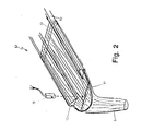
- Fig.2 shows the perspective view of the device of Fig. 1 with the tensioning bow in the retraction position
- Fig. 3 shows the device of FIG. 1 with the tensioning bow in the extraction position
- Fig. 4 shows the detailed axonometric view, partially in section, of the drive and guide means of the tensioning bow of the device of FIG.
- Fig. 5 shows the plan view, in section, of an alternative embodiment of the actuation means of the tensioning bow
- Figs. 6A and 6B show the plan view and, respectively, axonometric view of the actuation means of the tensioning arch according to another embodiment.
- a device for positioning the stockings in a machine for sewing tights with an optical sensor (18) for the detection of the garter line and comprising two paired forms of support for the stockings, each of the forms having two horizontal articulated arms (10) whose points are extended and connected by means of a bow (7) produced with a nylon thread and which is coplanar with the arm (10) and has the convexity directed towards the machine, provides that said bow (7) has its legs (71) housed in a sliding manner inside the arms (10) of the corresponding shape in their longitudinal direction between two positions , one of maximum retraction and the other of maximum extraction, to allow the bottom to be stretched out and before the form, and that said optical sensor (18) is in a position such that its light beam them vertical intercepts the garter line (17) in the area stretched by said bow (7) and therefore outside and before the form.
- the compressed air supplied by means of the connector (8) can advantageously be drawn from the same installation for the compression of the air with which each pantyhose sewing machine is equipped.
- the rods (4) comprise a stop element (14) on the side opposite to that of the guide ring (3): said stop element (14) being intended to be pushed towards the inside of the arms (10) by a pusher (20), thereby causing the bow (7) to exit relative to the arms (10).
- the operation is as follows.
- said tensioning bow (7) is rigidly fixed to only one of the rods (4), to allow its actuation by acting on only one of its legs (71) and therefore making provision to equip only one of the arms (10) of the form (13) with said drive and guide means: the other arm of the form being simply pierced longitudinally to allow the sliding of the other leg of the bow (7) when the latter is extracted or retracted.
- Attaching the arch (7) to one of the rods (4) has proven to be particularly advantageous for preventing the bow (7) from remaining in the extraction position by deforming into a rosette when the arms (10,30 ) of the form (13) are separated before sewing the tights.
Abstract
Dispositif pour le positionnement des bas dans une machine pour coudre les collants avec la détection de la ligne de jarretière (17) et comprenant deux formes jumelées (13) de support pour les bas, chacune des formes possédant deux bras horizontaux articulés (10) avec les pointes prolongées et reliées au moyen d'un archet (7) en nylon, dans lequel les jambes (71,72) dudit archet (7) sont logées de manière coulissante à l'intérieur des bras (10,30) de la pince (13) avec des moyens d'entraînement et de guidage prévus dans le bras (10) de la pince (13), avec une tige percée (4) à l'extrémité de laquelle est installé fixe le pied d'une jambe (71) de l'archet (7): le pied de l'autre jambe (72) étant logée avec jeu dans un trou (11) de l'autre bras de la pince (13); avec un tube (1) enfilé de manière solidaire sur un deuxième tube (2) calibré à l'intérieur pour le guidage du culot (5) de la tige précitée (4), à l'extrémité desdits tubes étant fixée une bague (3) pour le guidage de la pointe de la tige précitée (4); avec un ressort hélicoïdal (6) de poussée, enfilé sur la tige (4) à l'intérieur du tube (2) et comprimé de manière appropriée entre ladite bague (3) et ledit culot (5) de la tige (4); et avec des moyens de commande de l'extraction de l'archet de tendage (7) par rapport aux bras de la forme (13). <IMAGE>Device for positioning the stockings in a machine for sewing tights with the detection of the garter line (17) and comprising two paired forms (13) of support for the stockings, each of the forms having two horizontal articulated arms (10) with the points extended and connected by means of a nylon bow (7), in which the legs (71,72) of said bow (7) are slidably housed inside the arms (10,30) of the pliers (13) with drive and guide means provided in the arm (10) of the clamp (13), with a pierced rod (4) at the end of which is installed fixed the foot of one leg (71 ) of the bow (7): the foot of the other leg (72) being housed with play in a hole (11) in the other arm of the clamp (13); with a tube (1) threaded integrally on a second tube (2) calibrated inside for guiding the base (5) of the aforementioned rod (4), at the end of said tubes being fixed a ring (3 ) for guiding the tip of the aforementioned rod (4); with a helical thrust spring (6), threaded on the rod (4) inside the tube (2) and suitably compressed between said ring (3) and said base (5) of the rod (4); and with means for controlling the extraction of the tensioning bow (7) relative to the arms of the form (13). <IMAGE>
Description
La présente invention a pour objet un dispositif pour le positionnement automatique des bas dans une machine pour la formation des collants, avec la détection automatique de la ligne de jarretière.The present invention relates to a device for the automatic positioning of the stockings in a machine for the formation of tights, with the automatic detection of the garter line.
Il est connu que pour la fabrication des collants, deux bas sont découpés de manière appropriée longitudinalement à partir de l'extrémité ouverte, c'est-à-dire du bord élastique du corps du bas, jusqu'à une distance prédéterminée par rapport à la ligne de jarretière, laquelle sépare le corps de la jambe, et, successivement, les bords juxtaposés des deux bas ainsi découpés sont cousus ensemble.It is known that for the manufacture of tights, two stockings are cut out in an appropriate manner longitudinally from the open end, that is to say from the elastic edge of the stocking body, up to a predetermined distance from the garter line, which separates the body from the leg, and, successively, the juxtaposed edges of the two stockings thus cut are sewn together.
Dans ce but, les deux bas à coudre ensemble pour former un collant sont tout d'abord enfilés sur une paire de formes jumelées superposées, puis ils sont alignés verticalement et placés côte à côte de manière à obtenir la correspondance entre les bords élastiques et les lignes de jarretière des deux bas. Grâce à l'obtention de ladite correspondance, ladite coupe longitudinale conduit à la détermination de deux bords de longueur égale et positionnés de manière identique par rapport à la ligne de jarretière. Dans une phase successive, les bords juxtaposés des deux bas sont cousus ensemble et forment un collant: la couture étant exécutée sur toute la longueur des bords.For this purpose, the two stockings to be sewn together to form a pantyhose are first of all threaded on a pair of overlapping twin shapes, then they are aligned vertically and placed side by side so as to obtain the correspondence between the elastic edges and the garter lines of the two bottoms. By obtaining this correspondence, said longitudinal section leads to the determination of two edges of equal length and positioned identically with respect to the line of garter. In a successive phase, the juxtaposed edges of the two stockings are sewn together and form a pantyhose: the seam is executed over the entire length of the edges.
Il s'ensuit que, pour effectuer ladite couture avec la précision qui s'impose, il est nécessaire que la ligne de jarretière soit détectée de manière claire.It follows that, in order to carry out said sewing with the necessary precision, it is necessary that the line of garter is clearly detected.
Pour résoudre le problème de la détection de la ligne de jarretière sur un bas, on connaît des dispositifs équipés de capteurs optiques sensibles à la différence de densité entre le tissu de la jambe du bas et celle du tissu du corps.To solve the problem of detecting the garter line on a stocking, devices are known which are equipped with optical sensors sensitive to the difference in density between the fabric of the lower leg and that of the body tissue.
Mais, pour que la ligne de jarretière soit détectée de manière claire par lesdits capteurs, il est nécessaire que les bas soient disposés en correspondance des capteurs précités dans la position étendue, c'est-à-dire sans présenter de plis.However, in order for the garter line to be clearly detected by said sensors, it is necessary for the bottoms to be arranged in correspondence with the aforementioned sensors in the extended position, that is to say without having any folds.
D'après la demande de brevet japonais 1-312.410, on connaît un dispositif pour le positionnement des bas dans une machine pour la formation des collants, lequel comporte:
- - des capteurs optiques pour détecter la présence des bas sur les formes jumelées correspondantes, lesquels sont associés à des moyens de coulissement longitudinal des bas sur les formes;
- - des capteurs optiques pour détecter la ligne de jarretière des bas ainsi positionnés, lesquels sont associés à des moyens pour transférer lesdites lignes de jarretière dans une position prédéterminée sur les formes;
- - des capteurs optiques pour détecter le bord élastique des bas, lesquels sont associés à des moyens pour transférer lesdits bas dans une position prédéterminée sur les formes.
- - optical sensors to detect the presence of the stockings on the corresponding twin shapes, which are associated with means of longitudinal sliding of the stockings on the shapes;
- - optical sensors for detecting the garter line of stockings thus positioned, which are associated with means for transferring said garter lines to a predetermined position on the forms;
- - optical sensors for detecting the elastic edge of the stockings, which are associated with means for transferring said stockings to a predetermined position on the forms.
Le fonctionnement de ce dispositif connu peut être décrit de la manière suivante.The operation of this known device can be described as follows.
Les deux bas, sur lesquels travailler pour former un collant, sont enfilés de manière aléatoire sur les deux formes jumelées.The two stockings, on which to work to form a pantyhose, are strung randomly on the two paired shapes.
Lorsque les capteurs de détection de la présence de bas détectent leur présence, les moyens de positionnement des bords élastiques saisissent ces derniers et les introduisent à fond sur les formes et jusqu'à ce que la ligne de jarretière soit enfilée sur les formes et pour permettre ainsi leur détection par les capteurs correspondants. Après quoi des moyens associés auxdits capteurs permettent d'aligner les deux lignes de jarretière. Enfin, les capteurs de détection du bord élastique des bas se déplacent vers et jusqu'à une position d'alignement prédéterminée et les moyens associés de positionnement desdits bords élastiques permettent de les transférer jusqu'à ladite position d'alignement. A ce stade, les corps des bas se trouvent étendus, c'est-à-dire sans plis, sur une longueur prédéterminée et avec les bords élastiques et les lignes de jarretière alignés verticalement de manière à permettre l'exécution de l'opération de découpe successive, correctement.When the sensors for detecting the presence of stockings detect their presence, the means for positioning the elastic edges grip the latter and introduce them fully onto the forms and until the garter line is threaded onto the forms and to allow thus their detection by the corresponding sensors. After which means associated with said sensors make it possible to align the two lines of garter. Finally, the sensors for detecting the elastic edge of the stockings move towards and to a predetermined alignment position and the associated means for positioning said elastic edges make it possible to transfer them to said alignment position. At this stage, the bodies of the stockings are extended, that is to say without folds, over a predetermined length and with the elastic edges and the garter lines aligned vertically so as to allow the execution of the operation of successive cutting, correctly.
Mais ce dispositif de positionnement connu présente certains inconvénients. Le plus important de ceux-ci est la nécessité de déplacer le bord élastique et la jambe de chaque bas en deux phases distinctes et au moyen d'organes de positionnement différents, lesquels doivent travailler séparément. Et ceci implique une plus grande complexité de construction de la machine, au détriment de l'économie de production et d'exercice de celle-ci. Par ailleurs, à cause de la complexité de construction dudit dispositif connu, la fiabilité de la machine qui en est équipée s'avère fortement réduite, ce qui entraîne des interventions d'entretien plus fréquentes et des temps d'arrêt plus longs. Un autre inconvénient consiste dans le fait que le temps global nécessaire pour la réalisation d'un collant s'avère fortement conditionné par la vitesse d'exécution des opérations précitées de positionnement des bas sur les formes correspondantes, de sorte que, si on veut augmenter au maximum la vitesse de production des collants et en tenant compte du fait qu'à l'état actuel, il n'est pas possible de réduire ultérieurement les temps de découpe et de couture des bas, il n'est pas possible d'obtenir des marges de tolérances extrêmement étroites dans la détection des lignes de jarretière, ce qui entraîne des imprécisions dans la réalisation des collants.However, this known positioning device has certain drawbacks. The most important of these is the need to move the elastic edge and the leg of each stocking in two distinct phases and by means of different positioning members, which must work separately. And this implies a greater complexity of construction of the machine, to the detriment of the economy of production and exercise thereof. Furthermore, because of the construction complexity of said known device, the reliability of the machine which is equipped with it turns out to be greatly reduced, which leads to more frequent maintenance operations and longer downtimes. Another disadvantage consists in the fact that the overall time necessary for the production of a pantyhose turns out to be strongly conditioned by the speed of execution of the abovementioned operations of positioning the stockings on the corresponding shapes, so that, if one wishes to increase maximum production speed of tights and taking into account that in the current state, it is not possible to further reduce the cutting and sewing times of the stockings, it is not possible to obtain extremely narrow margins of tolerance in the detection of garter lines, which leads to inaccuracies in the production of tights.
Le but de la présente invention est d'éliminer les inconvénients mentionnés sans augmenter la longueur des formes.The object of the present invention is to eliminate the drawbacks mentioned without increasing the length of the shapes.
Ce résultat a été atteint, conformément à l'invention, en adoptant l'idée de réaliser un dispositif pour le positionnement automatique des bas dans une machine pour la formation des collants et comprenant deux formes jumelées superposées de support pour les bas, les bras de chaque forme étant prolongés et reliés en correspondance des pointes au moyen d'un archet coplanaire réalisé avec un fil en nylon, dont les bras sont asservis à des moyens d'entraînement le long des bras de la pince entre deux positions, l'une de rétraction maximum pour permettre l'introduction du bas sur la pince et l'autre d'extraction maximum pour obtenir la tension du corps et de la partie supérieure de la jambe du bas et même au-delà, c'est-à-dire avant la pince, de manière à permettre la détection de la ligne de jarretière en dehors, c'est-à-dire avant la pointe de la pince de support du bas correspondant.This result was achieved, in accordance with the invention, by adopting the idea of making a device for the automatic positioning of the stockings in a machine for the formation of tights and comprising two superimposed twin forms of support for the stockings, the arms of each form being extended and connected in correspondence of the points by means of a coplanar bow made with a nylon thread, the arms of which are controlled by drive means along the arms of the clamp between two positions, one of maximum retraction to allow the insertion of the bottom on the clamp and the other maximum extraction to obtain the tension of the body and the upper part of the lower leg and even beyond, that is to say before the clamp, so to allow detection of the garter line outside, that is to say before the tip of the support clip of the corresponding bottom.
Les avantages obtenus grâce à la présente invention consistent essentiellement en ce qu'il est possible d'obtenir le tendage du corps et de la zone supérieure des jambes de chaque bas en une seule phase et avec les mêmes moyens de déplacement; qui le temps de réalisation d'un collant s'avère considérablement réduit ou autrement que, pour un même temps utilisé, la vitesse de déplacement des bas est fortement réduite, au profit de la précision dans la détection des lignes de jarretière et, par conséquent, au profit de la qualité des collants réalisés; que le dispositif proposé est de réalisation simple et donc économique et fiable même après une utilisation continue très longue; que les machines pour la production des collants actuellement disponibles peuvent être facilement et rapidement équipées d'un dispositif conforme à l'invention.The advantages obtained thanks to the present invention essentially consist in the fact that it is possible to obtain the tightening of the body and of the upper zone of the legs of each stocking in a single phase and with the same means of movement; which the production time of a pantyhose turns out to be considerably reduced or otherwise that, for the same time used, the speed of movement of the stockings is greatly reduced, in favor of the precision in the detection of the garter lines and, consequently , to the benefit of the quality of the tights produced; that the proposed device is simple to make and therefore economical and reliable even after very long continuous use; that the machines for the production of tights currently available can be easily and quickly fitted with a device according to the invention.
Ces avantages et caractéristiques de l'invention ainsi que d'autres seront plus et mieux compris de chaque homme du métier à la lumière de la description qui va suivre et à l'aide des dessins annexés donnés à titre d'exemplification pratique de l'invention, mais à ne pas considérer dans le sens limitatif; dessins sur lesquels: la Fig. 1 représente une vue en plan, partiellement en coupe, d'une pince de machine pour coudre les collants, équipée d'un dispositif pour le positionnement du bas conformément à l'invention; la Fig.2 représente la vue en perspective du dispositif de la Fig. 1 avec l'archet de tendage dans la position de rétraction; la Fig. 3 représente le dispositif de la Fig. 1 avec l'archet de tendage dans la position d'extraction; la Fig. 4 représente la vue axonométrique détaillée, partiellement en coupe, des moyens d'entraînement et de guidage de l'archet de tendage du dispositif de la Fig. 1; la Fig. 5 représente la vue en plan, en coupe, d'une forme alternative de réalisation des moyens d'actionnement de l'archet de tendage; les Fig. 6A et 6B représentent la vue en plan et, respectivement, axonométrique des moyens d'actionnement de l'arche de tendage selon une autre forme de réalisation.These advantages and characteristics of the invention as well as others will be more and better understood by each person skilled in the art in the light of the description which follows and with the aid of the appended drawings given by way of practical example of the invention, but not to be considered in the limiting sense; drawings in which: FIG. 1 shows a plan view, partially in section, of a machine clamp for sewing tights, equipped with a device for positioning the stocking in accordance with the invention; Fig.2 shows the perspective view of the device of Fig. 1 with the tensioning bow in the retraction position; Fig. 3 shows the device of FIG. 1 with the tensioning bow in the extraction position; Fig. 4 shows the detailed axonometric view, partially in section, of the drive and guide means of the tensioning bow of the device of FIG. 1; Fig. 5 shows the plan view, in section, of an alternative embodiment of the actuation means of the tensioning bow; Figs. 6A and 6B show the plan view and, respectively, axonometric view of the actuation means of the tensioning arch according to another embodiment.
Réduit à sa structure essentielle et en référence aux figures 1-4 des dessins annexés, un dispositif selon l'invention pour le positionnement des bas dans une machine pour coudre les collants avec un capteur optique (18) pour la détection de la ligne de jarretière et comprenant deux formes jumelées de support pour les bas, chacune des formes possédant deux bras horizontaux articulés (10) dont les pointes sont prolongées et reliées au moyen d'un archet (7) réalisé avec un fil en nylon et lequel est coplanaire avec les bras (10) et présente la convexité dirigée vers la machine, prévoit que ledit archet (7) a ses jambes (71) logées de manière coulissante à l'intérieur des bras (10) de la forme correspondante dans leur direction longitudinale entre deux positions, l'une de rétraction maximum et l'autre d'extraction maximum, pour permettre de tendre le bas en dehors et avant la forme, et que ledit capteur optique (18) est dans une position telle que son faisceau lumineux vertical intercepte la ligne de jarretière (17) dans la zone tendue par ledit archet (7) et donc en dehors et avant la forme.Reduced to its essential structure and with reference to Figures 1-4 of the accompanying drawings, a device according to the invention for positioning the stockings in a machine for sewing tights with an optical sensor (18) for the detection of the garter line and comprising two paired forms of support for the stockings, each of the forms having two horizontal articulated arms (10) whose points are extended and connected by means of a bow (7) produced with a nylon thread and which is coplanar with the arm (10) and has the convexity directed towards the machine, provides that said bow (7) has its legs (71) housed in a sliding manner inside the arms (10) of the corresponding shape in their longitudinal direction between two positions , one of maximum retraction and the other of maximum extraction, to allow the bottom to be stretched out and before the form, and that said optical sensor (18) is in a position such that its light beam them vertical intercepts the garter line (17) in the area stretched by said bow (7) and therefore outside and before the form.
Plus précisément, ledit archet (7) en nylon est asservi:
- a) à des moyens d'entraînement et de guidage prévus dans les deux bras (10) de la forme (13) et comprenant pour chaque bras:
- - une tige percée (4) avec un culot (5) à l'extrémité de laquelle est installé fixe le pied de la jambe correspondante (71) de l'archet (7);
- - un premier tube (1) enfilé de manière solidaire sur un deuxième tube (2) calibré à l'intérieur pour le guidage du culot (5) de la tige précitée (4) et une bague (3) pour le guidage de la pointe de la tige précitée (4) étant fixée à l'extrémité desdits tubes;
- - un ressort hélicoïdal (6) de poussée, enfilé sur la tige (4) à l'intérieur du tube (2) et comprimé de manière appropriée entre ladite bague (3) et ledit culot (5) de la tige (4);
- b) à des moyens de commande pneumatique de la course active de la tige (4), c'est-à-dire d'extraction de l'archet de tendage (7) par rapport aux bras de la forme (13), avec un raccord (8) monté en ligne avec la tige (4) en correspondance de l'extrémité de chaque bras (10) de la forme (13) qui se trouve du côté opposé de l'archet (7) en nylon.
- a) to drive and guide means provided in the two arms (10) of the form (13) and comprising for each arm:
- - a pierced rod (4) with a base (5) at the end of which is installed fixes the foot of the corresponding leg (71) of the bow (7);
- - A first tube (1) threaded integrally on a second tube (2) calibrated inside for guiding the base (5) of the aforementioned rod (4) and a ring (3) for guiding the tip the aforementioned rod (4) being fixed to the end of said tubes;
- - a thrust helical spring (6), threaded on the rod (4) inside the tube (2) and compressed appropriately between said ring (3) and said base (5) of the rod (4);
- b) pneumatic control means of the active stroke of the rod (4), that is to say of extraction of the tensioning bow (7) relative to the arms of the form (13), with a fitting (8) mounted in line with the rod (4) corresponding to the end of each arm (10) of the shape (13) which is on the opposite side of the nylon bow (7).
L'air comprimé amené au moyen du raccord (8) peut être avantageusement soutiré à partir de la même installation pour la compression de l'air dont chaque machine à coudre les collants est équipée.The compressed air supplied by means of the connector (8) can advantageously be drawn from the same installation for the compression of the air with which each pantyhose sewing machine is equipped.
Selon une forme alternative de réalisation des moyens d'actionnement de l'archet (7) de tendage, et en référence à la Fig. 5 des dessins annexés, les tiges (4) comportent un élément de butée (14) du côté opposé à celui de la bague de guidage (3): ledit élément de butée (14) étant destiné à être poussé vers l'intérieur des bras (10) par un poussoir (20), en entraînant ainsi la sortie de l'archet (7) par rapport aux bras (10).According to an alternative embodiment of the actuation means of the tensioning bow (7), and with reference to FIG. 5 of the accompanying drawings, the rods (4) comprise a stop element (14) on the side opposite to that of the guide ring (3): said stop element (14) being intended to be pushed towards the inside of the arms (10) by a pusher (20), thereby causing the bow (7) to exit relative to the arms (10).
Selon une autre forme de réalisation des moyens d'actionnement de l'archet (7) de tendage, et en référence aux Fig. 6A et 6B des dessins annexés, sur le culot (5) de la tige (4) qui est logée dans le bras gauche (10) (respectivement droit) de la forme (13) est fixée une des extrémité d'un câble flexible correspondant (15) muni d'une gaine, l'autre extrémité étant fixée à la partie tournante (21) de l'articulation (22) correspondant au bras droit (10) (respectivement gauche) de la forme (13), et le ressort (6) est enfilé sur ledit câble (15) de manière que la traction des deux câbles (15) amène l'archet de tendage (7) dans la position de rétraction et le relâchement des deux câbles (15) permet au ressort (6) de pousser l'archet de tendage (7) hors de la forme (13).According to another embodiment of the means for actuating the tensioning bow (7), and with reference to FIGS. 6A and 6B of the accompanying drawings, on the base (5) of the rod (4) which is housed in the left arm che (10) (respectively straight) of the form (13) is fixed one end of a corresponding flexible cable (15) provided with a sheath, the other end being fixed to the rotating part (21) of the articulation (22) corresponding to the right arm (10) (respectively left) of the form (13), and the spring (6) is threaded on said cable (15) so that the traction of the two cables (15) brings the tensioning bow (7) in the retracted position and the release of the two cables (15) allows the spring (6) to push the tensioning bow (7) out of the form (13).
Le fonctionnement est le suivant.The operation is as follows.
Après que le bas (16) a été enfilé autour des bras (10) et que de l'air comprimé est envoyé à l'intérieur des tubes (2) à l'archet de tendage (7) d'une forme (13) (Voir Fig. 1) à travers les raccords (8), et la pression exercée par l'air comprimé sur les culots (5) des tiges percées (4) provoque la translation en avant de ces dernières, en surmontant la résistance des ressorts (6). En conséquence, l'archet de tendage (7) est forcé à sortir des bras (10) de la forme (13) et la zone de bas qui se trouve à cheval sur la ligne de jarretière (17) est élargie, c'est-à-dire tendue, en éliminant les plis afin de permettre au capteur optique (18) de détecter de manière claire la ligne de jarretière (17). Au terme de l'opération de positionnement du bas, qui est effectuée en une unique phase et consiste à déplacer le bas sur la forme (13) en éloignant son bord élastique (19) de la pointe de la forme jusqu'à ce que le capteur (18) détecte la ligne de jarretière (17), l'alimentation de l'air comprimé cesse et les ressorts (6) ramènent en arrière dans la forme (13) les tiges percées (4) et, avec elles, l'archet de tendage (7).After the bottom (16) has been threaded around the arms (10) and compressed air is sent inside the tubes (2) to the tension bow (7) of a shape (13) (See Fig. 1) through the fittings (8), and the pressure exerted by the compressed air on the bases (5) of the drilled rods (4) causes them to move forward, overcoming the resistance of the springs (6). As a result, the tensioning bow (7) is forced out of the arms (10) of the form (13) and the bottom area which is astride the garter line (17) is widened, this is that is to say, stretched, by eliminating the folds in order to allow the optical sensor (18) to clearly detect the line of garter (17). At the end of the bottom positioning operation, which is carried out in a single phase and consists in moving the bottom on the form (13) by moving its elastic edge (19) away from the tip of the form until the sensor (18) detects the garter line (17), the supply of compressed air ceases and the springs (6) bring the pierced rods (4) back in shape (13) and, with them, the tensioning bow (7).
En alternative, conformément à l'invention, il est prévu que ledit archet de tendage (7) soit fixé de manière rigide à une seule des tiges (4), pour permettre son actionnement en agissant sur une seule de ses jambes (71) et en prévoyant donc de n'équiper qu'un seul des bras (10) de la forme (13) avec lesdits moyens d'entraînement et de guidage: l'autre bras de la forme étant simplement percé longitudinalement pour permettre le coulissement de l'autre jambe de l'archet (7) lorsque ce dernier est extrait ou rentré. La fixation de l'arche (7) à une des tiges (4) s'est avérée particulièrement avantageuse pour éviter que l'archet (7) ne reste en position d'extraction en se déformant en rosette lorsque les bras (10,30) de la forme (13) sont écartés avant la couture des collants.Alternatively, in accordance with the invention, it is provided that said tensioning bow (7) is rigidly fixed to only one of the rods (4), to allow its actuation by acting on only one of its legs (71) and therefore making provision to equip only one of the arms (10) of the form (13) with said drive and guide means: the other arm of the form being simply pierced longitudinally to allow the sliding of the other leg of the bow (7) when the latter is extracted or retracted. Attaching the arch (7) to one of the rods (4) has proven to be particularly advantageous for preventing the bow (7) from remaining in the extraction position by deforming into a rosette when the arms (10,30 ) of the form (13) are separated before sewing the tights.
Claims (6)
et en ce que les moyens de détection de la ligne de jarretière (17) comprennent un capteur optique (18) dans une position telle, par rapport à la forme (13) correspondante, que son faisceau lumineux vertical intercepte la ligne de jarretière (17) qui se trouve en position tendue sur ledit archet (7) et donc en dehors et avant la forme (13).1) Device for positioning the stockings in a machine for sewing pantyhose comprising two twin forms (13) of support for the stockings, each of the forms having two horizontal articulated arms (10) whose points are extended and connected by means of a bow (7) produced with a nylon thread and which is coplanar with the arms (10) and has the convexity directed towards the machine, and further comprising means (18) for the detection of the garter line (17) from the bottom threaded onto the corresponding form, characterized in that said bow (7) has its legs (71) housed in a sliding manner inside the arms (10) of the form (13) in their longitudinal direction and in that 'he is enslaved:
and in that the means for detecting the garter line (17) comprises an optical sensor (18) in such a position, relative to the corresponding shape (13), that its vertical light beam intercepts the garter line (17 ) which is in the stretched position on said bow (7) and therefore outside and before the form (13).
Applications Claiming Priority (2)
| Application Number | Priority Date | Filing Date | Title |
|---|---|---|---|
| ITFI920067A IT1259630B (en) | 1992-03-13 | 1992-03-13 | DEVICE FOR THE AUTOMATIC POSITIONING OF THE CLAZE IN THE SEWING MACHINE FOR COLLANTS |
| ITFI920067 | 1992-03-13 |
Publications (2)
| Publication Number | Publication Date |
|---|---|
| EP0560735A1 true EP0560735A1 (en) | 1993-09-15 |
| EP0560735B1 EP0560735B1 (en) | 1995-10-25 |
Family
ID=11350012
Family Applications (1)
| Application Number | Title | Priority Date | Filing Date |
|---|---|---|---|
| EP93830068A Expired - Lifetime EP0560735B1 (en) | 1992-03-13 | 1993-02-24 | Apparatus for automatic positioning of stockings in a panty hose sewing machine |
Country Status (7)
| Country | Link |
|---|---|
| US (1) | US5309853A (en) |
| EP (1) | EP0560735B1 (en) |
| JP (1) | JP2542322B2 (en) |
| CA (1) | CA2091532A1 (en) |
| DE (1) | DE69300688T2 (en) |
| IT (1) | IT1259630B (en) |
| MX (1) | MX9301383A (en) |
Cited By (1)
| Publication number | Priority date | Publication date | Assignee | Title |
|---|---|---|---|---|
| EP0630999A1 (en) * | 1993-06-25 | 1994-12-28 | SOLIS S.r.l. | Procedure and device in order to dispose two tubular products in a predetermined position on a corresponding support |
Families Citing this family (1)
| Publication number | Priority date | Publication date | Assignee | Title |
|---|---|---|---|---|
| IT1262541B (en) * | 1993-10-18 | 1996-07-02 | Solis Srl | DEVICE FOR POSITIONING THE PORTION OF THE FOOT OF TUBULAR KNITTED ARTICLES |
Citations (4)
| Publication number | Priority date | Publication date | Assignee | Title |
|---|---|---|---|---|
| US3126134A (en) * | 1964-03-24 | Hose seam flattening device | ||
| US3197094A (en) * | 1962-08-01 | 1965-07-27 | Doctor E Fowler | Power operated hosiery extension machine |
| US4192242A (en) * | 1977-04-02 | 1980-03-11 | Detexomat Machinery Limited | Hosiery toe closers |
| US4374501A (en) * | 1980-07-18 | 1983-02-22 | Consolidated Foods Corporation | Garment toe closing assembly |
Family Cites Families (1)
| Publication number | Priority date | Publication date | Assignee | Title |
|---|---|---|---|---|
| JPH03173597A (en) * | 1989-11-30 | 1991-07-26 | Takatori Haitetsuku:Kk | Automatic positioning device of panty stocking in trunk part sewing machine |
-
1992
- 1992-03-13 IT ITFI920067A patent/IT1259630B/en active IP Right Grant
-
1993
- 1993-02-24 EP EP93830068A patent/EP0560735B1/en not_active Expired - Lifetime
- 1993-02-24 DE DE69300688T patent/DE69300688T2/en not_active Expired - Fee Related
- 1993-03-11 CA CA002091532A patent/CA2091532A1/en not_active Abandoned
- 1993-03-12 MX MX9301383A patent/MX9301383A/en not_active Application Discontinuation
- 1993-03-12 US US08/030,570 patent/US5309853A/en not_active Expired - Fee Related
- 1993-03-15 JP JP5080035A patent/JP2542322B2/en not_active Expired - Lifetime
Patent Citations (4)
| Publication number | Priority date | Publication date | Assignee | Title |
|---|---|---|---|---|
| US3126134A (en) * | 1964-03-24 | Hose seam flattening device | ||
| US3197094A (en) * | 1962-08-01 | 1965-07-27 | Doctor E Fowler | Power operated hosiery extension machine |
| US4192242A (en) * | 1977-04-02 | 1980-03-11 | Detexomat Machinery Limited | Hosiery toe closers |
| US4374501A (en) * | 1980-07-18 | 1983-02-22 | Consolidated Foods Corporation | Garment toe closing assembly |
Cited By (1)
| Publication number | Priority date | Publication date | Assignee | Title |
|---|---|---|---|---|
| EP0630999A1 (en) * | 1993-06-25 | 1994-12-28 | SOLIS S.r.l. | Procedure and device in order to dispose two tubular products in a predetermined position on a corresponding support |
Also Published As
| Publication number | Publication date |
|---|---|
| CA2091532A1 (en) | 1993-09-14 |
| ITFI920067A0 (en) | 1992-03-13 |
| DE69300688T2 (en) | 1996-07-04 |
| JP2542322B2 (en) | 1996-10-09 |
| DE69300688D1 (en) | 1995-11-30 |
| ITFI920067A1 (en) | 1993-09-13 |
| IT1259630B (en) | 1996-03-25 |
| JPH06205886A (en) | 1994-07-26 |
| MX9301383A (en) | 1994-08-31 |
| US5309853A (en) | 1994-05-10 |
| EP0560735B1 (en) | 1995-10-25 |
Similar Documents
| Publication | Publication Date | Title |
|---|---|---|
| CH640020A5 (en) | METHOD AND SEWING MACHINE FOR INSERTING AN ELASTIC TAPE AT THE CORNERS OF A FITTED SHEET. | |
| FR2638148A1 (en) | PROGRESSIVE ACTING CURVE PLOTTER COMPRISING A BRAKE FOR A PAPER DEBIT ROLLER | |
| EP0560735B1 (en) | Apparatus for automatic positioning of stockings in a panty hose sewing machine | |
| WO2006053909A1 (en) | Automatic machine for tying a knot using a string end of a tubular sleeve for sealing same by constriction when the knot is tightened | |
| CH677509A5 (en) | ||
| EP0630999B1 (en) | Procedure and device in order to dispose two tubular products in a predetermined position on a corresponding support | |
| FR2467902A1 (en) | Positioning device - for garment pieces fed to sewing machine, corrects position for seaming | |
| FR2499243A1 (en) | DEVICE FOR MEASURING OR CONTROLLING THE BELT TENSION | |
| FR2650807A1 (en) | Device permitting the opening and closing of containers having a flattened shape when empty | |
| EP0533637A1 (en) | Machine for automatical sewing of toes of two stockings, especially of panty hose | |
| FR2510150A1 (en) | WEFT BRAKE FOR NON-SHUTTER WEAVING MACHINE | |
| FR2461045A1 (en) | CIRCULAR MACHINE FOR BOTTOMS AND THE LIKE WITH CAM DRUM AND PROGRAMMING DRUM COAXIALLY MOUNTED WITH NEEDLE CYLINDER | |
| EP0636730B1 (en) | Procedure and device for automatically positioning stockings in a machine to form panty hose | |
| FR2596701A3 (en) | Apparatus for preparing adhesive handles for carrying packets | |
| EP0648880A1 (en) | Apparatus for positioning the foot portion of tubular knitted products | |
| FR2611650A1 (en) | DEVICE FOR TIETING A FLEXIBLE LINK | |
| EP0203243A1 (en) | Process and apparatus for automatically positioning the toe end of a stocking at the open end of an everting tube for sewing purposes | |
| BE1001681A5 (en) | Apparatus for positioning a chain of points in a sewing. | |
| FR2609294A1 (en) | DEVICE FOR SECTIONING AND POSITIONING A CHAIN OF SEWING STITCHES FORMING A STITCH STITCH ON FABRIC WITH A SEWING MACHINE | |
| FR2505885A1 (en) | DEVICE FOR INSERTING THE WEFT YARN ENDS ON THE EDGE OF THE FABRIC INTO A WEAVING MATERIAL WITHOUT SHUTTLE | |
| FR2513668A1 (en) | KNITTING | |
| FR2646839A1 (en) | APPARATUS AND METHOD FOR SUPPLYING LABELS | |
| EP0120752A1 (en) | Apparatus and method for turning briefs inside out | |
| EP0802271A1 (en) | Apparatus for sewing the toe portion of tubular knitted products | |
| CH582106A5 (en) | Twisting device for large dia. cables - having drawing and feed devices mounted on support moveable between winding up positions |
Legal Events
| Date | Code | Title | Description |
|---|---|---|---|
| PUAI | Public reference made under article 153(3) epc to a published international application that has entered the european phase |
Free format text: ORIGINAL CODE: 0009012 |
|
| AK | Designated contracting states |
Kind code of ref document: A1 Designated state(s): DE FR GB IT |
|
| 17P | Request for examination filed |
Effective date: 19931220 |
|
| 17Q | First examination report despatched |
Effective date: 19950331 |
|
| GRAA | (expected) grant |
Free format text: ORIGINAL CODE: 0009210 |
|
| AK | Designated contracting states |
Kind code of ref document: B1 Designated state(s): DE FR GB IT |
|
| REF | Corresponds to: |
Ref document number: 69300688 Country of ref document: DE Date of ref document: 19951130 |
|
| ITF | It: translation for a ep patent filed |
Owner name: ING. DR. LAZZARO MARTINI S.R.L. |
|
| GBT | Gb: translation of ep patent filed (gb section 77(6)(a)/1977) |
Effective date: 19960106 |
|
| PLBE | No opposition filed within time limit |
Free format text: ORIGINAL CODE: 0009261 |
|
| STAA | Information on the status of an ep patent application or granted ep patent |
Free format text: STATUS: NO OPPOSITION FILED WITHIN TIME LIMIT |
|
| 26N | No opposition filed | ||
| REG | Reference to a national code |
Ref country code: GB Ref legal event code: IF02 |
|
| PGFP | Annual fee paid to national office [announced via postgrant information from national office to epo] |
Ref country code: DE Payment date: 20060216 Year of fee payment: 14 |
|
| PGFP | Annual fee paid to national office [announced via postgrant information from national office to epo] |
Ref country code: GB Payment date: 20060222 Year of fee payment: 14 |
|
| PGFP | Annual fee paid to national office [announced via postgrant information from national office to epo] |
Ref country code: FR Payment date: 20060227 Year of fee payment: 14 |
|
| GBPC | Gb: european patent ceased through non-payment of renewal fee |
Effective date: 20070224 |
|
| REG | Reference to a national code |
Ref country code: FR Ref legal event code: ST Effective date: 20071030 |
|
| PG25 | Lapsed in a contracting state [announced via postgrant information from national office to epo] |
Ref country code: DE Free format text: LAPSE BECAUSE OF NON-PAYMENT OF DUE FEES Effective date: 20070901 |
|
| PG25 | Lapsed in a contracting state [announced via postgrant information from national office to epo] |
Ref country code: GB Free format text: LAPSE BECAUSE OF NON-PAYMENT OF DUE FEES Effective date: 20070224 Ref country code: FR Free format text: LAPSE BECAUSE OF NON-PAYMENT OF DUE FEES Effective date: 20070228 |
|
| PGFP | Annual fee paid to national office [announced via postgrant information from national office to epo] |
Ref country code: IT Payment date: 20080228 Year of fee payment: 16 |
|
| PG25 | Lapsed in a contracting state [announced via postgrant information from national office to epo] |
Ref country code: IT Free format text: LAPSE BECAUSE OF NON-PAYMENT OF DUE FEES Effective date: 20090224 |