EP0560677A1 - Heatable laminates glass, containing resistance-wires in the thermoplastic interlayer - Google Patents
Heatable laminates glass, containing resistance-wires in the thermoplastic interlayer Download PDFInfo
- Publication number
- EP0560677A1 EP0560677A1 EP93400613A EP93400613A EP0560677A1 EP 0560677 A1 EP0560677 A1 EP 0560677A1 EP 93400613 A EP93400613 A EP 93400613A EP 93400613 A EP93400613 A EP 93400613A EP 0560677 A1 EP0560677 A1 EP 0560677A1
- Authority
- EP
- European Patent Office
- Prior art keywords
- wires
- groups
- glazing
- laminated glass
- antenna
- Prior art date
- Legal status (The legal status is an assumption and is not a legal conclusion. Google has not performed a legal analysis and makes no representation as to the accuracy of the status listed.)
- Granted
Links
Images


Classifications
-
- H—ELECTRICITY
- H05—ELECTRIC TECHNIQUES NOT OTHERWISE PROVIDED FOR
- H05B—ELECTRIC HEATING; ELECTRIC LIGHT SOURCES NOT OTHERWISE PROVIDED FOR; CIRCUIT ARRANGEMENTS FOR ELECTRIC LIGHT SOURCES, IN GENERAL
- H05B3/00—Ohmic-resistance heating
- H05B3/84—Heating arrangements specially adapted for transparent or reflecting areas, e.g. for demisting or de-icing windows, mirrors or vehicle windshields
- H05B3/86—Heating arrangements specially adapted for transparent or reflecting areas, e.g. for demisting or de-icing windows, mirrors or vehicle windshields the heating conductors being embedded in the transparent or reflecting material
-
- B—PERFORMING OPERATIONS; TRANSPORTING
- B32—LAYERED PRODUCTS
- B32B—LAYERED PRODUCTS, i.e. PRODUCTS BUILT-UP OF STRATA OF FLAT OR NON-FLAT, e.g. CELLULAR OR HONEYCOMB, FORM
- B32B17/00—Layered products essentially comprising sheet glass, or glass, slag, or like fibres
- B32B17/06—Layered products essentially comprising sheet glass, or glass, slag, or like fibres comprising glass as the main or only constituent of a layer, next to another layer of a specific material
- B32B17/10—Layered products essentially comprising sheet glass, or glass, slag, or like fibres comprising glass as the main or only constituent of a layer, next to another layer of a specific material of synthetic resin
- B32B17/10005—Layered products essentially comprising sheet glass, or glass, slag, or like fibres comprising glass as the main or only constituent of a layer, next to another layer of a specific material of synthetic resin laminated safety glass or glazing
- B32B17/10165—Functional features of the laminated safety glass or glazing
- B32B17/10376—Laminated safety glass or glazing containing metal wires
- B32B17/10385—Laminated safety glass or glazing containing metal wires for ohmic resistance heating
-
- H—ELECTRICITY
- H01—ELECTRIC ELEMENTS
- H01Q—ANTENNAS, i.e. RADIO AERIALS
- H01Q1/00—Details of, or arrangements associated with, antennas
- H01Q1/12—Supports; Mounting means
- H01Q1/1271—Supports; Mounting means for mounting on windscreens
- H01Q1/1278—Supports; Mounting means for mounting on windscreens in association with heating wires or layers
-
- H—ELECTRICITY
- H05—ELECTRIC TECHNIQUES NOT OTHERWISE PROVIDED FOR
- H05B—ELECTRIC HEATING; ELECTRIC LIGHT SOURCES NOT OTHERWISE PROVIDED FOR; CIRCUIT ARRANGEMENTS FOR ELECTRIC LIGHT SOURCES, IN GENERAL
- H05B2203/00—Aspects relating to Ohmic resistive heating covered by group H05B3/00
- H05B2203/014—Heaters using resistive wires or cables not provided for in H05B3/54
Definitions
- the present invention relates to an electrically heatable laminated glass glazing fitted with thin resistance wires arranged at a short distance from each other in the intermediate thermoplastic layer.
- Electrically heatable laminated glass panes of this type are known in various embodiments and are used in particular in motor vehicles, for example as a heatable windshield or as a heatable rear window.
- the metallic resistance wires inserted in the intermediate thermoplastic layer are generally very thin and have a diameter of 0.005 to 0.1 mm so as not to impede vision through the glazing. They are deposited in straight or wavy form, usually at mutual distances of around 3 to 10 mm.
- the electrical resistance wires are distributed uniformly over the entire surface of the glazing or in an area of the glazing intended for vision, so that the corresponding surface of the glazing heats up uniformly when it is supplied with heating current and that the moisture layer present on the glazing is thus eliminated uniformly.
- the electrical resistance wires in groups in the laminated glass glazing so that, respectively, networks or groups of wires having a series of wires extending parallel to each other. others are arranged at a distance of, for example, a few centimeters.
- networks or groups of wires having a series of wires extending parallel to each other. others are arranged at a distance of, for example, a few centimeters.
- these groups of wires are arranged in the horizontal direction, one obtains an arrangement of wires which looks a bit like the scope of a music book.
- Such an arrangement of resistance wires has the effect that the defrosting intended to make a layer of moisture disappear begins in strips.
- Unlike a glazing heated in a completely uniform manner it can be clearly seen that it is an electrically heatable glass although the resistance wires proper as such cannot be distinguished or only then during a very close examination.
- the diffracted optical images which are formed due to the presence of the resistance wires when looking through the glazing in the direction of sources of Spot lights, especially the headlights of oncoming and following vehicles, were particularly visible.
- the X-shaped diffracted images which form respectively around the point light sources are not as marked as in the case of known heating glazings where the resistance wires are uniformly distributed, but they act on the eye subjectively and obviously disturb it all the more since the areas of the glazing comprised between the groups of wires are free from these diffraction phenomena and the human eye has the particular attention drawn to the repeated alternation of areas optically flawless and of zones causing diffraction phenomena.
- the object of the invention is to produce an electrically heatable laminated glass glazing of the type mentioned in the preamble with an arrangement in groups of resistance wires, this glazing being such that the diffraction phenomena occurring in the case of point light sources are less noticeable and have no particularly annoying effect on the human eye.
- the heated surface of the laminated glass glazing is generally furnished uniformly by the resistance wires, several resistance wires neighboring each other are grouped respectively into a group of wires and are connected to the power supply lines and, between these groups of wires connected to the power supply lines, groups of wires made up of several resistor wires neighboring each other are respectively separated by at least one heating current supply line.
- the invention takes advantage of the known fact that, for the human eye, the alternating action of bands showing diffraction phenomena and bands free of diffraction phenomena is particularly troublesome and creates consciously, in the areas in the form of bands which are found between the groups of wires used for heating, conditions which, from the point of view of diffraction phenomena, are identical to those prevailing in the zones of the groups of wires. In this way, on the one hand, the strip defrosting effect remains entirely maintained, while, on the other hand, optically identical conditions from the point of view of diffraction phenomena occur throughout the area likely to be heated.
- the metal wires which are not connected to the heating current supply line are provided in whole or in part with a supply line electrically separated from the heating conductors of so that they also perform an electrical function. It is thus possible for example to occasionally connect the resistance wires in question as additional heating conductors if necessary. In this case, these resistance wires are electrically separated only from one of the two collecting lines and are equipped with a clean current supply line which is isolated from the electrically separated collecting line and can be connected to the power source by a suitable switch. Furthermore, the separate resistance wires in question can be used as antenna wires. In this case, it is recommended to separate the resistance wires from the two header lines or to electrically insulate them from them.
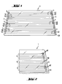
- FIG. 1 shows a laminated glass glazing suitable for use as an electrically heatable rear window and on the intermediate thermoplastic layer of which are arranged two collector lines 2, 3 having the form, for example, of tinned copper sheets extending along the two lateral edges and, between these collecting lines 2, 3, groups 4, 5 of resistance wires extending in the horizontal direction.
- the groups of wires 4, 5 are shown diagrammatically as each comprising two individual conductors 40, 50, but they are in reality groups of several resistance wires neighboring each other, for example, from three to ten individual wires each.
- the groups of resistance wires 4 are in electrically conductive contact with both the collecting line 2 and the collecting line 3
- the groups of resistance wires 5 have no electrical contact at least with the one of the two collecting lines 2 or 3. In the drawings, these groups terminate a short distance from the collecting line 2 or 3.
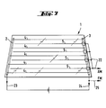
- the arrangement in groups of the resistance wires 40, 50 can be observed in FIGS. 2 and 3.
- the groups of wires 4 and 5 respectively consist of five individual wires 40 laid in a straight line.
- the individual wires 40 are for example tungsten wires with a gauge of 0.01 mm. They are fixed to the intermediate thermoplastic layer according to known methods before the juxtaposition and the union of the individual layers of the laminated glass glazing, just like the collecting lines 2 and 3.
- the mutual spacing of the individual wires 40, 50 is for example from 2 to 8 mm. All the individual wires 50 of the group of wires 5 terminate before the collecting line 3 so that no electrical contact is established between the wires of the group of wires 5 and the collecting line 3.
- the embodiment of heated glazing shown in FIG. 3 has in principle the same structure, that is to say groups of wires 4 ′ consisting of several individual wires 40 ′ which are in contact with the collecting line 3, while the individual wires 50 ′ of groups of wires 5 'arranged between the groups of wires 4' have no electrical contact with the collecting line 3.
- the individual wires are laid in a sinusoid, for example, using devices such as those described in documents DE 16 79 930 and DE 41 01 984.
- the resistance wires placed on the intermediate thermoplastic layer are thin tungsten wires of a caliber of about 0.01 mm, spaced apart from each other by 3 to 6 mm.
- FIG. 4 A first embodiment for this purpose is shown in FIG. 4. All the individual wires 40, 50 of the groups of wires 4 and 5 are brought to the thermoplastic film 8, which will then be bonded to two individual glass sheets to form the laminated glass glazing, over the collecting line 3 up to the edge 9 and are then fixed on the film 8 and this, in the traditional way. If necessary, the individual wires 40, 50 are cut along the edge 9 of the sheet 8. When all the film has been filled in this way with the resistance wires, the individual wires 50 forming the groups of wires 5 will be cut along the line 10 at a short distance from the collecting line 3. If necessary, the same cutting of the individual wires 50 from the groups of wires 5 will also be Also carried out at a short distance in front of the other collecting line.
- FIG. 5 is shown a corresponding arrangement in the form of a longitudinal section through a glazing of laminated glass finished in the area of a collecting line.
- the collecting lines 3 consist of a lower thin strip 3 ′ and of a strip thin upper 3 "between which the resistance wires 15 corresponding to the groups of wires 4 are embedded.
- a section 17 d 'an electrical insulating film is interposed between the lower thin strip 3' and the wires 16.
- a section 18 of an electrical insulating film is interposed between the wires 16 of the group of wires 5 and the upper copper thin strip 3 ".
- the procedure is shown in FIG. 6.
- a section 17 of an electrical insulating film On the wires 16 of the groups of wires 5 there is a section of thin metal sheet 20 which is in electrical contact with the wires 16.
- This section of metal sheet 20 is provided with a connection strip, not shown, which emerges laterally. glazing in laminated glass and is used for the electrical connection of these groups of wires.
- a section 18 of an electrical insulating film Above this thin metal sheet 20 is again arranged a section 18 of an electrical insulating film, which provides electrical insulation against the upper thin strip 3 ".
- the groups of wires 5 contacted separately can serve in particular as antenna elements.
- Figs. 7 to 9 are shown various examples of how the individual wire sets can be used as antenna elements.
- connection bars to the groups of wires 5 emerge laterally from the laminated glass glazing and are connected to a common connection line 22.
- the electrical signal taken from the antenna wire 22 can serve as a radio antenna signal for the AM and FM domains.
- the heating wire zone which is connected to the battery via the power supply lines 23, 24 and can be connected to the FM antenna input of the radio via a connection line 25.
- the resistance wire groups are again represented here only by a line respectively.
- FIG. 8 Another possibility of applying the son zones of the laminated glass is shown in FIG. 8.
- two groups of wires 5 are interconnected and brought into contact with a connection line 28 while two other groups of wires 51 are also interconnected and brought into contact with a connection line 29.
- the line power supply 24 of the heating wire zone is again fitted with a connection line 30 by which the antenna voltage is obtained from the heating wire zone.
- the three connection lines 28, 29 and 30 form a diversity reception system with three antennas in which the zone of wires brought into contact by the connection line 28 forms the antenna channel K1, the zone of wires connected by the connection line 29, the antenna channel K2, and the area of heating wires in contact with the connection line 30, the antenna channel K3.
- the connections of the individual wire zones can be located on different sides.
- Fig. 9 shows an embodiment having a large area FM antenna field, which is formed by three groups of wires 52. These three groups of wires 52 are connected to each other and the connection line 32 which is brought into contact with this area of wires is provided for a connection to the FM antenna input of the radio.
- this embodiment has a small, low-capacity antenna area in the upper region of the laminated glass pane. This small antenna area is formed by the group of wires 5 and is equipped with a connection line 33 which is provided for a connection to the antenna input AM of the radio.
- the heating wire area which is connected to the battery via the power supply lines 23 and 24, in this case has no antenna function.
Abstract
Description
La présente invention concerne un vitrage en verre feuilleté chauffable électriquement équipé de fils de résistance minces agencés à faible distance les uns des autres dans la couche thermoplastique intermédiaire.The present invention relates to an electrically heatable laminated glass glazing fitted with thin resistance wires arranged at a short distance from each other in the intermediate thermoplastic layer.
Les vitrages en verre feuilletés chauffables électriquement de ce type sont connus dans diverses formes de réalisation et sont utilisés en particulier dans les véhicules automobiles, par exemple comme pare- brise chauffable ou comme lunette arrière chauffable. Les fils de résistance métalliques insérés dans la couche thermoplastique intermédiaire sont en règle générale très minces et ont un diamètre de 0,005 à 0,1 mm de manière à ne pas gêner la vision à travers le vitrage. Ils sont déposés sous forme rectiligne ou ondulée et ce, habituellement à des distances mutuelles d'environ 3 à 10 mm.Electrically heatable laminated glass panes of this type are known in various embodiments and are used in particular in motor vehicles, for example as a heatable windshield or as a heatable rear window. The metallic resistance wires inserted in the intermediate thermoplastic layer are generally very thin and have a diameter of 0.005 to 0.1 mm so as not to impede vision through the glazing. They are deposited in straight or wavy form, usually at mutual distances of around 3 to 10 mm.
Habituellement, les fils de résistance électriques sont répartis uniformément sur toute la surface du vitrage ou dans une zone du vitrage destinée à la vision, de telle sorte que la surface correspondante du vitrage se réchauffe uniformément lorsqu'on l'alimente en courant de chauffage et que la couche d'humidité présente sur le vitrage soit de la sorte éliminée uniformément.Usually, the electrical resistance wires are distributed uniformly over the entire surface of the glazing or in an area of the glazing intended for vision, so that the corresponding surface of the glazing heats up uniformly when it is supplied with heating current and that the moisture layer present on the glazing is thus eliminated uniformly.
Mais on peut également, comme on le sait, agencer les fils de résistance électriques par groupes dans le vitrage en verre feuilleté de telle sorte que, respectivement, des réseaux ou des groupes de fils présentant une série de fils s'étendant parallèlement les uns aux autres soient agencés à distance de, par exemple, quelques centimètres. Lorsque ces groupes de fils sont agencés dans la direction horizontale, on obtient un agencement de fils qui ressemble un peu à la portée d'un cahier de musique. Un tel agencement des fils de résistance a pour effet que le dégivrage destiné à faire disparaître une couche d'humidité s'amorce par bandes. Contrairement à un vitrage chauffé de manière tout à fait uniforme, on peut constater nettement qu'il s'agit d'un verre chauffable électriquement bien que les fils de résistance proprement dits en tant que tels ne puissent être distingués ou alors uniquement lors d'un examen de très près.However, it is also possible, as is known, to arrange the electrical resistance wires in groups in the laminated glass glazing so that, respectively, networks or groups of wires having a series of wires extending parallel to each other. others are arranged at a distance of, for example, a few centimeters. When these groups of wires are arranged in the horizontal direction, one obtains an arrangement of wires which looks a bit like the scope of a music book. Such an arrangement of resistance wires has the effect that the defrosting intended to make a layer of moisture disappear begins in strips. Unlike a glazing heated in a completely uniform manner, it can be clearly seen that it is an electrically heatable glass although the resistance wires proper as such cannot be distinguished or only then during a very close examination.
On a constaté, dans le cas d'un tel agencement en groupes des fils de résistance, que les images optiques diffractées, qui se forment du fait de la présence des fils de résistance lorsqu'on regarde à travers le vitrage en direction de sources de lumière ponctuelles, en particulier les phares de véhicules venant en sens inverse ou suivant, étaient particulièrementvisi- bles. Certes, les images diffractées en forme de X qui se forment respectivement autour des sources de lumière ponctuelles ne sont pas aussi marquées que dans le cas des vitrages chauffants connus où les fils de résistance sont répartis de manière uniforme, mais elles agissent sur l'oeil humain de manière subjective et le perturbent manifestement d'autant plus que les zones du vitrage comprises entre les groupes de fils sont exemptes de ces phénomènes de diffraction et que l'oeil humain a tout particulièrement l'attention attirée par l'alternance répétée de zones optiquement irréprochables et de zones provoquant des phénomènes de diffraction.It has been found, in the case of such an arrangement in groups of the resistance wires, that the diffracted optical images, which are formed due to the presence of the resistance wires when looking through the glazing in the direction of sources of Spot lights, especially the headlights of oncoming and following vehicles, were particularly visible. Admittedly, the X-shaped diffracted images which form respectively around the point light sources are not as marked as in the case of known heating glazings where the resistance wires are uniformly distributed, but they act on the eye subjectively and obviously disturb it all the more since the areas of the glazing comprised between the groups of wires are free from these diffraction phenomena and the human eye has the particular attention drawn to the repeated alternation of areas optically flawless and of zones causing diffraction phenomena.
On peut par ailleurs, d'une manière connue, éviter les phénomènes de diffraction cités en noyant les fils de résistance, selon un agencement le plus irrégulier possible, dans la couche thermoplastique intermédiaire (document DE-OS 20 13 112). Un agencement irrégulier des fils de résistance peut être réalisé, par exemple selon les documents DE-PS 23 50 427 et DE-PS 23 65 831, en fixant les fils de résistance sous tension mécanique ou déformation élastique sur la couche thermoplastique intermédiaire et en soumettant ensuite la couche thermoplastique intermédiaire à un traitement de contraction. En pratique, ces procédés sont cependant difficiles à réaliser.It is also possible, in a known manner, to avoid the diffraction phenomena mentioned by embedding the resistance wires, in an arrangement as irregular as possible, in the intermediate thermoplastic layer (document DE-OS 20 13 112). An irregular arrangement of the resistance wires can be produced, for example according to documents DE-PS 23 50 427 and DE-PS 23 65 831, by fixing the resistance wires under mechanical tension or elastic deformation on the intermediate thermoplastic layer and by subjecting then the intermediate thermoplastic layer to a contraction treatment. In practice, these methods are however difficult to carry out.
L'invention a pour but de réaliser un vitrage en verre feuilleté chauffable électriquement du type mentionné dans le préambule avec un agencement en groupes des fils de résistance, ce vitrage étant tel que les phénomènes de diffraction se produisant dans le cas de sources de lumière ponctuelles se fassent moins remarquer et n'exercent aucun effet particulièrement gênant sur l'oeil humain.The object of the invention is to produce an electrically heatable laminated glass glazing of the type mentioned in the preamble with an arrangement in groups of resistance wires, this glazing being such that the diffraction phenomena occurring in the case of point light sources are less noticeable and have no particularly annoying effect on the human eye.
Ce but est atteint selon l'invention de la manière suivante : la surface chauffée du vitrage en verre feuilleté est garnie dans l'ensemble uniformément par les fils de résistance, plusieurs fils de résistance voisins les uns des autres sont rassemblés respectivement en un groupe de fils et sont connectés aux lignes d'alimentation en courant et, entre ces groupes de fils connectés aux lignes d'alimentation en courant, des groupes de fils constitués de plusieurs fils de résistance voisins les uns des autres sont respectivement séparés d'au moins une ligne d'alimentation en courant de chauffage.This object is achieved according to the invention in the following manner: the heated surface of the laminated glass glazing is generally furnished uniformly by the resistance wires, several resistance wires neighboring each other are grouped respectively into a group of wires and are connected to the power supply lines and, between these groups of wires connected to the power supply lines, groups of wires made up of several resistor wires neighboring each other are respectively separated by at least one heating current supply line.
L'invention tire profit du fait connu que, pour l'oeil humain, l'action alternée de bandes accusant des phénomènes de diffraction et de bandes exemptes de phénomènes de diffraction est particulièrement gênante et crée consciemment, dans les zones en forme de bandes qui se trouvent entre les groupes de fils servant au chauffage, des conditions qui, du point de vue des phénomènes de diffraction, sont identiques à celles qui règnent dans les zones des groupes de fils. De cette manière, d'une part, l'effet de dégivrage par bandes reste entièrement maintenu, tandis que, d'autre part, des conditions optiquement identiques du point de vue des phénomènes de diffraction se produisent dans toute la zone susceptible d'être chauffée.The invention takes advantage of the known fact that, for the human eye, the alternating action of bands showing diffraction phenomena and bands free of diffraction phenomena is particularly troublesome and creates consciously, in the areas in the form of bands which are found between the groups of wires used for heating, conditions which, from the point of view of diffraction phenomena, are identical to those prevailing in the zones of the groups of wires. In this way, on the one hand, the strip defrosting effect remains entirely maintained, while, on the other hand, optically identical conditions from the point of view of diffraction phenomena occur throughout the area likely to be heated.
Dans un autre développement de l'invention, les fils métalliques qui ne sont pas connectés à la ligne d'alimentation en courant de chauffage sont pourvus en totalité ou en partie d'une ligne d'alimentation électriquement séparée des conducteurs de chauffage de telle sorte qu'ils remplissent également une fonction électrique. Il est ainsi possible par exemple de connecter occasionnellement les fils de résistance en question comme conducteurs de chauffage supplémentaires en cas de besoin. Dans ce cas, ces fils de résistance ne sont séparés électriquement que de l'une des deux lignes collectrices et sont équipés d'une ligne d'alimentation en courant propre qui est isolée vis-à-vis de la ligne collectrice électriquement séparée et peut être connectée à la source de courant par un interrupteur approprié. Par ailleurs, les fils de résistance séparés en question, peuvent être utilisés comme fils d'antenne. Dans ce cas, on recommande de séparer les fils de résistance des deux lignes collectrices ou de les isoler électriquement vis-à-vis de celles-ci.In another development of the invention, the metal wires which are not connected to the heating current supply line are provided in whole or in part with a supply line electrically separated from the heating conductors of so that they also perform an electrical function. It is thus possible for example to occasionally connect the resistance wires in question as additional heating conductors if necessary. In this case, these resistance wires are electrically separated only from one of the two collecting lines and are equipped with a clean current supply line which is isolated from the electrically separated collecting line and can be connected to the power source by a suitable switch. Furthermore, the separate resistance wires in question can be used as antenna wires. In this case, it is recommended to separate the resistance wires from the two header lines or to electrically insulate them from them.
Diverses formes de réalisation et divers développements du vitrage en verre feuilleté selon l'invention seront décrits ci-dessous plus en détail avec référence aux dessins annexés dans lesquels :
- La Fig. 1 est une vue schématique d'un vitrage en verre feuilleté chauffable électriquement selon l'invention;
- la Fig. 2 est une vue fragmentaire de la Fig. 1 montrant des fils de résistance rectilignes;
- la Fig. 3 est une vue fragmentaire de la Fig. 1 montrant des fils de résistance déposés en sinusoïdes;
- la Fig. 4 est une vue partielle avec des fils métalliques séparés par sectionnement par groupes;
- la Fig. 5 est une vue en coupe le long d'une ligne collectrice;
- la Fig. 6 est une vue en coupe le long d'une ligne collectrice avec une mise en contact distincte des fils de résistance séparés;
- la Fig. 7 représente schématiquement un vitrage chauffant selon l'invention avec fonction simultanée d'antenne;
- la Fig. 8 représente un vitrage chauffant selon l'invention avec trois canaux d'antenne, et
- la Fig. 9 représente un vitrage chauffant selon l'invention avec une zone d'antenne FM de grande surface et une zone d'antenne AM de petite surface.
- Fig. 1 is a schematic view of an electrically heatable laminated glass glazing according to the invention;
- Fig. 2 is a fragmentary view of FIG. 1 showing straight resistance wires;
- Fig. 3 is a fragmentary view of FIG. 1 showing resistance wires deposited in sinusoids;
- Fig. 4 is a partial view with metal wires separated by sectioning in groups;
- Fig. 5 is a sectional view along a collector line;
- Fig. 6 is a sectional view along a collecting line with separate contacting of the separate resistance wires;
- Fig. 7 schematically represents a heating glazing according to the invention with simultaneous antenna function;
- Fig. 8 represents a heating glazing according to the invention with three antenna channels, and
- Fig. 9 shows a heating glazing according to the invention with a large area FM antenna area and a small area AM antenna area.
La vue schématique de la Fig. 1 montre un vitrage en verre feuilleté propre à être utilisé comme lunette arrière chauffable électriquement et sur la couche thermoplastique intermédiaire duquel sont agencés deux lignes collectrices 2, 3 ayant la forme, par exemple, de feuilles de cuivre étamées s'étendant le long des deux bords latéraux et, entre ces lignes collectrices 2, 3, des groupes 4, 5 de fils de résistance s'étendant dans la direction horizontale. Les groupes de fils 4, 5 sont représentés schématiquement comme comprenant chacun deux conducteurs individuels 40, 50, mais il s'agit en réalité de groupes de plusieurs fils de résistance voisins les uns des autres, parexemple, de trois à dix fils individuels chacun.The schematic view of FIG. 1 shows a laminated glass glazing suitable for use as an electrically heatable rear window and on the intermediate thermoplastic layer of which are arranged two
Tandis que les groupes de fils de résistance 4 sont en contact conducteur de l'électricité à la fois avec la ligne collectrice 2 et la ligne collectrice 3, les groupes de fils de résistance 5 n'ont pas de contact électrique au moins avec l'une des deux lignes collectrices 2 ou 3. Dans les dessins, ces groupes se terminent à courte distance de la ligne collectrice 2 ou 3.While the groups of
L'agencement par groupes des fils de résistance 40, 50 peut être observé sur les Fig. 2 et 3. Comme le montre la Fig. 2, les groupes de fils 4 et 5 sont respectivement constitués de cinq fils individuels 40 posés en ligne droite. Les fils individuels 40 sont par exemple des fils de tungstène d'un calibre de 0,01 mm. Ils sont fixés sur la couche thermoplastique intermédiaire selon des méthodes connues avant la juxtaposition et l'union des couches individuelles du vitrage en verre feuilleté, tout comme les lignes collectrices 2 et 3. L'écart mutuel des fils individuels 40, 50 est par exemple de 2 à 8 mm. Tous les fils individuels 50 du groupe de fils 5 se terminent avant la ligne collectrice 3 de sorte qu'aucun contact électrique n'est établi entre les fils du groupe de fils 5 et la ligne collectrice 3.The arrangement in groups of the
La forme de réalisation de vitrage chauffant représentée sur la Fig. 3 a en principe la même structure, c'est-à-dire des groupes de fils 4' constitués de plusieurs fils individuels 40' qui sont en contact avec la ligne collectrice 3, tandis que les fils individuels 50' des groupes de fils 5' disposés entre les groupes de fils 4' n'ont aucun contact électrique avec la ligne collectrice 3. Dans ce cas cependant, les fils individuels sont posés en sinusoïde, par exemple, à l'aide de dispositifs tels que ceux qui sont décrits dans les documents DE 16 79 930 et DE 41 01 984. Les fils de résistance posés sur la couche thermoplastique intermédiaire sont de minces fils de tungstène d'un calibre d'environ 0,01 mm, espacé de distances mutuelles de 3 à 6 mm.The embodiment of heated glazing shown in FIG. 3 has in principle the same structure, that is to say groups of
La réalisation pratique de la mesure visant à supprimer le contact électrique avec l'une et/ou l'autre des lignes collectrices dans le cas des groupes de fils individuels peut s'effectuer de diverses manières. Une première forme de réalisation à cet effet est représentée sur la Fig. 4. Tous les fils individuels 40, 50 des groupes de fils 4 et 5 sont amenés sur la pellicule thermoplastique 8, qui sera par la suite collée à deux feuilles de verre individuelles pour former le vitrage en verre feuilleté, par dessus la ligne collectrice 3 jusqu'au bord 9 et sont alors fixés sur la pellicule 8 et ce, de manière traditionnelle. Le cas échéant, les fils individuels 40, 50 sont coupés le long du bord 9 de la feuille 8. Lorsque toute la pellicule aura été garnie de cette manière des fils de résistance, les fils individuels 50 formant les groupes de fils 5 seront sectionnés le long de la ligne 10 à courte distance de la ligne collectrice 3. Le cas échéant, le même sectionnement des fils individuels 50 des groupes de fils 5 sera également réalisé à courte distance devant l'autre ligne collectrice.The practical realization of the measure aimed at eliminating the electrical contact with one and / or the other of the collecting lines in the case of the groups of individual wires can be carried out in various ways. A first embodiment for this purpose is shown in FIG. 4. All the
Une autre possibilité de réalisation de l'invention consiste à empêcher le contact des groupée de fils 5 avec les lignes collectrices en intercalant, dans les zones correspondantes entre la ligne collectrice et les fils de résistance, une pellicule isolante électrique. Sur la Fig. 5 est représenté un agencement correspondant sous la forme d'une coupe longitudinale à travers un vitrage en verre feuilleté fini dans la zone d'une ligne collectrice. On peut y observer les deux feuilles de verre individuelles 12 et 13, qui sont reliées l'une à l'autre via la couche thermoplastique intermédiaire 14. Les lignes collectrices 3 sont constituées d'une bande mince inférieure 3'et d'une bande mince supérieure 3" entre lesquelles les fils de résistance 15 correspondant aux groupes de fils 4 sont noyés. Pour empêcher tout contact électrique avec les bandes minces 3' dans le cas des fils de résistance 16 appartenant aux groupes de fils 5, une section 17 d'une pellicule isolante électrique est intercalée entre la bande mince inférieure 3' et les fils 16. De même, une section 18 d'une pellicule isolante électrique est intercalée entre les fils 16 du groupe de fils 5 et la bande mince de cuivre supérieure 3".Another possible embodiment of the invention consists in preventing contact of the group of
Au cas où les fils 16 des groupes de fils 5 devraient remplir une fonction électrique, par exemple, comme fils d'antenne, et devraient également être mis en contact à cette fin, on procédera de la manière représentée sur la Fig. 6. Entre la bande mince de cuivre inférieure 3' et les fils 16 des groupes de fils 5 est à nouveau intercalée une section 17 d'une pellicule isolante électrique. Sur les fils 16 des groupes de fils 5 se trouve une section de feuille de métal mince 20 qui est en contact électrique avec les fils 16. Cette section de feuille de métal 20 est dotée d'une barrette de connexion non représentée, qui ressort latéralement du vitrage en verre feuilleté et sert à la connexion électrique de ces groupes de fils. Au-dessus de cette feuille de métal mince 20 est à nouveau agencée une section 18 d'une pellicule isolante électrique, qui assure l'isolation électrique vis-à-vis de la bande mince supérieure 3".In the case where the
Les groupes de fils 5 contactés séparément peuvent servir en particulier d'éléments d'antenne. Dans les Fig. 7 à 9 sont reproduits divers exemples de la manière dont les ensembles de fils individuels peuvent être utilisés comme éléments d'antenne.The groups of
Dans la forme de réalisation représentée sur la Fig. 7, quatre groupes de fils 5, qui ne sont représentés ici que par une ligne, sont isolés électriquement vis-à-vis des lignes collectrices 2 et 3, vis-à-vis de la ligne collectrice 3 si l'on se réfère à la Fig. 6. Les barrettes de connexion aux groupes de fils 5 ressortent latéralement du vitrage en verre feuilleté et sont connectés à une ligne de connexion commune 22. Le signal électrique prélevé sur le fil d'antenne 22 peut servir de signal d'antenne radio pour les domaines AM et FM. Cependant, il est également possible de séparer la fonction d'antenne des fils et d'utiliser pour le domaine FM le signal d'antenne présent sur la ligne de connexion 22, tandis que le signal d'antenne pour le domaine FM peut être obtenu de la zone de fils de chauffage, qui est reliée à la batterie via les lignes d'alimentation en courant 23, 24 et peut être connectée à 'entrée d'antenne FM de la radio via une ligne de connexion 25. De même, les groupes de fils de résistance ne sont à nouveau représentés ici respectivement que par une ligne.In the embodiment shown in FIG. 7, four groups of
Une autre possibilité d'application des zones de fils du verre feuilleté est représentée sur la Fig. 8. Dans ce cas, deux groupes de fils 5 sont interconnectés et mis en contact avec une ligne de connexion 28 tandis que deux autres groupes de fils 51 sont également interconnectés et mis en contact avec une ligne de connexion 29. En outre, la ligne d'alimentation en courant 24 de la zone de fils de chauffage est à nouveau équipée d'une ligne de connexion 30 par laquelle la tension d'antenne est obtenue de la zone de fils de chauffage. Les trois lignes de connexion 28, 29 et 30 forment un système de réception en diversité à trois antennes dans lequel la zone de fils mise en contact par la ligne de connexion 28 forme le canal d'antenne K1, la zone de fils connectée par la ligne de connexion 29, le canal d'antenne K2, et la zone de fils de chauffage en contact avec la ligne de connexion 30, le canal d'antenne K3. Pour produire une plus forte différenciation des caractéristiques d'antenne, les connections des zones de fils individuelles peuvent être situées sur des côtés différents.Another possibility of applying the son zones of the laminated glass is shown in FIG. 8. In this case, two groups of
La Fig. 9 représente une forme de réalisation présentant un champ d'antenne FM de grande surface, qui est formé par trois groupes de fils 52. Ces trois groupes de fils 52 sont reliés les uns aux autres et la ligne de connexion 32 qui est mise en contact avec cette zone de fils est prévue pour une liaison à l'entrée d'antenne FM de la radio. En outre, cette forme de réalisation présente une petite zone d'antenne de faible capacité dans la région supérieure du vitrage en verre feuilleté. Cette petite zone d'antenne est formée par le groupe de fils 5 et est équipée d'une ligne de connexion 33 qui est prévue pour une liaison à l'entrée d'antenne AM de la radio. La zone de fils de chauffage, qui est connectée à la batterie via les lignes d'alimentation en courant 23 et 24, n'a dans ce cas aucune fonction d'antenne.Fig. 9 shows an embodiment having a large area FM antenna field, which is formed by three groups of
Claims (11)
Applications Claiming Priority (2)
| Application Number | Priority Date | Filing Date | Title |
|---|---|---|---|
| DE4207638 | 1992-03-11 | ||
| DE4207638A DE4207638C2 (en) | 1992-03-11 | 1992-03-11 | Heatable laminated glass pane with resistance wires arranged in the thermoplastic intermediate layer |
Publications (2)
| Publication Number | Publication Date |
|---|---|
| EP0560677A1 true EP0560677A1 (en) | 1993-09-15 |
| EP0560677B1 EP0560677B1 (en) | 1999-08-04 |
Family
ID=6453720
Family Applications (1)
| Application Number | Title | Priority Date | Filing Date |
|---|---|---|---|
| EP93400613A Expired - Lifetime EP0560677B1 (en) | 1992-03-11 | 1993-03-10 | Heatable laminates glass, containing resistance-wires in the thermoplastic interlayer |
Country Status (4)
| Country | Link |
|---|---|
| EP (1) | EP0560677B1 (en) |
| AT (1) | ATE182842T1 (en) |
| DE (2) | DE4207638C2 (en) |
| ES (1) | ES2137234T3 (en) |
Cited By (7)
| Publication number | Priority date | Publication date | Assignee | Title |
|---|---|---|---|---|
| EP0690665A1 (en) * | 1994-06-30 | 1996-01-03 | Saint-Gobain Vitrage | Windshield equiped with a static electricity protection circuit |
| WO2000004748A1 (en) * | 1998-07-14 | 2000-01-27 | T W Woods Construction Pty. Ltd. | Window security device |
| FR2781789A1 (en) * | 1998-08-03 | 2000-02-04 | Saint Gobain Vitrage | Transparent substrate, for plasma screens, flat high frequency lamps and building or aircraft glazing, is assembled with a thermoplastic film containing adjacent metal wires having different undulations |
| WO2001054223A1 (en) * | 2000-01-24 | 2001-07-26 | Receptec L.L.C. | Vehicle window antenna system |
| WO2005060044A1 (en) * | 2003-12-17 | 2005-06-30 | Robert Bosch Gmbh | Vehicle windshield-integrated antenna |
| US20160316520A1 (en) * | 2015-04-24 | 2016-10-27 | Guanping Feng | Low-power electro-thermal film devices and methods for making the same |
| EP2618632A4 (en) * | 2010-09-14 | 2018-03-28 | LG Chem, Ltd. | Heating element and manufacturing method thereof |
Families Citing this family (5)
| Publication number | Priority date | Publication date | Assignee | Title |
|---|---|---|---|---|
| DE10106125B4 (en) * | 2001-02-08 | 2014-04-10 | Delphi Technologies, Inc. | Vehicle window with antenna structures |
| DE10126869A1 (en) * | 2001-06-01 | 2002-12-19 | Saint Gobain Sekurit D Gmbh | Electrically heated disc |
| DE20321682U1 (en) | 2003-11-07 | 2008-11-13 | Saint-Gobain Sekurit Deutschland Gmbh & Co. Kg | Heatable composite disc |
| DE102011001867A1 (en) | 2011-04-07 | 2012-10-11 | Hella Kgaa Hueck & Co. | Headlight for vehicle, particularly heavy duty truck, has unit formed by incandescent lamp as temperature radiator for defrosting lens cover, where light module with light emitting diode light source is gripped in headlight housing |
| WO2016000927A1 (en) * | 2014-07-01 | 2016-01-07 | Saint-Gobain Glass France | Heatable laminated side pane |
Citations (7)
| Publication number | Priority date | Publication date | Assignee | Title |
|---|---|---|---|---|
| LU66174A1 (en) * | 1971-09-28 | 1973-04-02 | ||
| DE2350427B1 (en) * | 1973-10-08 | 1975-01-02 | Kinon Glas Spiegel | Process for the production of electrically heatable composite panes, in which the metal wires are fixed in an irregular arrangement on a thermoplastic intermediate film, thereby avoiding diffraction of the light falling through |
| US3971029A (en) * | 1974-01-14 | 1976-07-20 | Toyota Jidosha Kogyo Kabushiki Kaisha | Window antenna device for use in motor vehicle |
| FR2592544A1 (en) * | 1985-12-26 | 1987-07-03 | Nippon Sheet Glass Co Ltd | CONDUCTIVE GLASS PLATE, PARTICULARLY FOR MOTOR VEHICLES FOR DEFROSTING OR THE LIKE. |
| EP0297328A2 (en) * | 1987-06-12 | 1989-01-04 | FUBA Hans Kolbe & Co | Arrangement of several antennas in a glass window to get antenna diversity |
| DE3910031A1 (en) * | 1988-03-31 | 1989-10-19 | Nippon Sheet Glass Co Ltd | Vehicle window antenna |
| EP0382895A1 (en) * | 1989-02-15 | 1990-08-22 | Robert Bosch Gmbh | Vehicle window antenna |
Family Cites Families (8)
| Publication number | Priority date | Publication date | Assignee | Title |
|---|---|---|---|---|
| DE1679930C2 (en) * | 1967-05-20 | 1985-02-07 | Bethge, Dietrich, Riehen | Device for laying thread-like material, in particular the thinnest wire, in the surface of thermoplastic material serving as a carrier material, in particular for producing panel heating elements |
| DE2013112A1 (en) * | 1970-03-19 | 1971-09-30 | Partsch E | Wire carrying foil for heated laminatedglass |
| US3745309A (en) * | 1972-10-31 | 1973-07-10 | Gen Electric | Electrically heated transparent panel |
| DE3226393A1 (en) * | 1982-07-15 | 1984-01-19 | Flachglas AG, 8510 Fürth | HEATABLE VEHICLE WINDOW |
| DE3741244A1 (en) * | 1987-12-05 | 1989-06-15 | Bosch Gmbh Robert | HEATED DISC |
| JPH0277910U (en) * | 1988-08-24 | 1990-06-14 | ||
| JPH0758850B2 (en) * | 1989-07-24 | 1995-06-21 | セントラル硝子株式会社 | Glass antenna for vehicle |
| DE4101984C2 (en) * | 1991-01-24 | 1995-02-09 | Ver Glaswerke Gmbh | Device for depositing and fixing a resistance wire on a thermoplastic carrier film for producing an electrically heatable laminated glass pane |
-
1992
- 1992-03-11 DE DE4207638A patent/DE4207638C2/en not_active Expired - Fee Related
-
1993
- 1993-03-10 ES ES93400613T patent/ES2137234T3/en not_active Expired - Lifetime
- 1993-03-10 DE DE69325837T patent/DE69325837T2/en not_active Expired - Fee Related
- 1993-03-10 EP EP93400613A patent/EP0560677B1/en not_active Expired - Lifetime
- 1993-03-10 AT AT93400613T patent/ATE182842T1/en not_active IP Right Cessation
Patent Citations (7)
| Publication number | Priority date | Publication date | Assignee | Title |
|---|---|---|---|---|
| LU66174A1 (en) * | 1971-09-28 | 1973-04-02 | ||
| DE2350427B1 (en) * | 1973-10-08 | 1975-01-02 | Kinon Glas Spiegel | Process for the production of electrically heatable composite panes, in which the metal wires are fixed in an irregular arrangement on a thermoplastic intermediate film, thereby avoiding diffraction of the light falling through |
| US3971029A (en) * | 1974-01-14 | 1976-07-20 | Toyota Jidosha Kogyo Kabushiki Kaisha | Window antenna device for use in motor vehicle |
| FR2592544A1 (en) * | 1985-12-26 | 1987-07-03 | Nippon Sheet Glass Co Ltd | CONDUCTIVE GLASS PLATE, PARTICULARLY FOR MOTOR VEHICLES FOR DEFROSTING OR THE LIKE. |
| EP0297328A2 (en) * | 1987-06-12 | 1989-01-04 | FUBA Hans Kolbe & Co | Arrangement of several antennas in a glass window to get antenna diversity |
| DE3910031A1 (en) * | 1988-03-31 | 1989-10-19 | Nippon Sheet Glass Co Ltd | Vehicle window antenna |
| EP0382895A1 (en) * | 1989-02-15 | 1990-08-22 | Robert Bosch Gmbh | Vehicle window antenna |
Cited By (10)
| Publication number | Priority date | Publication date | Assignee | Title |
|---|---|---|---|---|
| EP0690665A1 (en) * | 1994-06-30 | 1996-01-03 | Saint-Gobain Vitrage | Windshield equiped with a static electricity protection circuit |
| FR2721857A1 (en) * | 1994-06-30 | 1996-01-05 | Saint Gobain Vitrage | GLAZING EQUIPPED WITH AN ELECTROSTATIC PROTECTION CIRCUIT |
| WO2000004748A1 (en) * | 1998-07-14 | 2000-01-27 | T W Woods Construction Pty. Ltd. | Window security device |
| FR2781789A1 (en) * | 1998-08-03 | 2000-02-04 | Saint Gobain Vitrage | Transparent substrate, for plasma screens, flat high frequency lamps and building or aircraft glazing, is assembled with a thermoplastic film containing adjacent metal wires having different undulations |
| WO2001054223A1 (en) * | 2000-01-24 | 2001-07-26 | Receptec L.L.C. | Vehicle window antenna system |
| WO2005060044A1 (en) * | 2003-12-17 | 2005-06-30 | Robert Bosch Gmbh | Vehicle windshield-integrated antenna |
| US7719475B2 (en) | 2003-12-17 | 2010-05-18 | Robert Bosch Gmbh | Window-integrated antenna in vehicles |
| EP2618632A4 (en) * | 2010-09-14 | 2018-03-28 | LG Chem, Ltd. | Heating element and manufacturing method thereof |
| US20160316520A1 (en) * | 2015-04-24 | 2016-10-27 | Guanping Feng | Low-power electro-thermal film devices and methods for making the same |
| US10631372B2 (en) * | 2015-04-24 | 2020-04-21 | Guanping Feng | Low-power electro-thermal film devices and methods for making the same |
Also Published As
| Publication number | Publication date |
|---|---|
| DE4207638C2 (en) | 1994-01-27 |
| EP0560677B1 (en) | 1999-08-04 |
| ES2137234T3 (en) | 1999-12-16 |
| DE69325837D1 (en) | 1999-09-09 |
| DE69325837T2 (en) | 2000-02-17 |
| DE4207638A1 (en) | 1993-09-23 |
| ATE182842T1 (en) | 1999-08-15 |
Similar Documents
| Publication | Publication Date | Title |
|---|---|---|
| EP1803327B1 (en) | Transparent window pane provided with a resistive heating coating | |
| EP1454509B1 (en) | Heated pane with an electrically-conductive surface coating | |
| EP1623480B1 (en) | Window aerial for motor vehicles | |
| EP0394089B1 (en) | Electrically heated car windshield | |
| EP0427619B1 (en) | Heated laminated glass window for vehicles | |
| EP0560677B1 (en) | Heatable laminates glass, containing resistance-wires in the thermoplastic interlayer | |
| EP1680945B1 (en) | Heated laminated glazing | |
| BE1021978B1 (en) | AUTOMOBILE GLAZING | |
| EP0975045A1 (en) | Window antenna for a car | |
| CA2637247C (en) | Transparent glazing provided with laminated heating system | |
| EP3319794A1 (en) | Motor vehicle glazing | |
| FR2608844A1 (en) | VEHICLE WINDOW ANTENNA USING TRANSPARENT CONDUCTIVE FILM | |
| FR2811778A1 (en) | ELECTROCHEMICAL DEVICE OF THE ELECTROCHROME TYPE OR PHOTOVOLTAIC DEVICE AND ITS ELECTRICAL CONNECTION MEANS | |
| WO2007085599A1 (en) | Automotive glazing | |
| EP2772117B1 (en) | Heated windshield | |
| EP0773706B1 (en) | Electrically heatable laminated window pane for motor vehicles | |
| WO2009013327A1 (en) | Glazing including electroluminescent elements | |
| EP0506521B1 (en) | Laminated heating window | |
| EP0690665A1 (en) | Windshield equiped with a static electricity protection circuit | |
| EP0643548A2 (en) | Electrically heated laminated glass window | |
| FR2743973A1 (en) | GLAZING COMPRISING A HEATING NETWORK AND METHOD FOR MANUFACTURING SUCH GLAZING | |
| BE658389A (en) |
Legal Events
| Date | Code | Title | Description |
|---|---|---|---|
| PUAI | Public reference made under article 153(3) epc to a published international application that has entered the european phase |
Free format text: ORIGINAL CODE: 0009012 |
|
| AK | Designated contracting states |
Kind code of ref document: A1 Designated state(s): AT BE CH DE ES FR GB IT LI LU PT SE |
|
| 17P | Request for examination filed |
Effective date: 19940307 |
|
| 17Q | First examination report despatched |
Effective date: 19970213 |
|
| GRAG | Despatch of communication of intention to grant |
Free format text: ORIGINAL CODE: EPIDOS AGRA |
|
| GRAG | Despatch of communication of intention to grant |
Free format text: ORIGINAL CODE: EPIDOS AGRA |
|
| GRAH | Despatch of communication of intention to grant a patent |
Free format text: ORIGINAL CODE: EPIDOS IGRA |
|
| GRAH | Despatch of communication of intention to grant a patent |
Free format text: ORIGINAL CODE: EPIDOS IGRA |
|
| RAP1 | Party data changed (applicant data changed or rights of an application transferred) |
Owner name: VEGLA VEREINIGTE GLASWERKE GMBH Owner name: SAINT-GOBAIN VITRAGE |
|
| RAP1 | Party data changed (applicant data changed or rights of an application transferred) |
Owner name: SEKURIT SAINT GOBAIN DEUTSCHLAND GMBH & CO. KG Owner name: SAINT-GOBAIN VITRAGE |
|
| GRAA | (expected) grant |
Free format text: ORIGINAL CODE: 0009210 |
|
| AK | Designated contracting states |
Kind code of ref document: B1 Designated state(s): AT BE CH DE ES FR GB IT LI LU PT SE |
|
| REF | Corresponds to: |
Ref document number: 182842 Country of ref document: AT Date of ref document: 19990815 Kind code of ref document: T |
|
| REG | Reference to a national code |
Ref country code: CH Ref legal event code: EP |
|
| REF | Corresponds to: |
Ref document number: 69325837 Country of ref document: DE Date of ref document: 19990909 |
|
| REG | Reference to a national code |
Ref country code: CH Ref legal event code: NV Representative=s name: KIRKER & CIE SA |
|
| ITF | It: translation for a ep patent filed |
Owner name: RACHELI & C. S.R.L. |
|
| GBT | Gb: translation of ep patent filed (gb section 77(6)(a)/1977) |
Effective date: 19991019 |
|
| REG | Reference to a national code |
Ref country code: ES Ref legal event code: FG2A Ref document number: 2137234 Country of ref document: ES Kind code of ref document: T3 |
|
| REG | Reference to a national code |
Ref country code: PT Ref legal event code: SC4A Free format text: AVAILABILITY OF NATIONAL TRANSLATION Effective date: 19991104 |
|
| PLBE | No opposition filed within time limit |
Free format text: ORIGINAL CODE: 0009261 |
|
| STAA | Information on the status of an ep patent application or granted ep patent |
Free format text: STATUS: NO OPPOSITION FILED WITHIN TIME LIMIT |
|
| 26N | No opposition filed | ||
| REG | Reference to a national code |
Ref country code: GB Ref legal event code: IF02 |
|
| PGFP | Annual fee paid to national office [announced via postgrant information from national office to epo] |
Ref country code: PT Payment date: 20060224 Year of fee payment: 14 |
|
| PGFP | Annual fee paid to national office [announced via postgrant information from national office to epo] |
Ref country code: DE Payment date: 20060302 Year of fee payment: 14 |
|
| PGFP | Annual fee paid to national office [announced via postgrant information from national office to epo] |
Ref country code: GB Payment date: 20060308 Year of fee payment: 14 |
|
| PGFP | Annual fee paid to national office [announced via postgrant information from national office to epo] |
Ref country code: FR Payment date: 20060310 Year of fee payment: 14 |
|
| PGFP | Annual fee paid to national office [announced via postgrant information from national office to epo] |
Ref country code: AT Payment date: 20060313 Year of fee payment: 14 |
|
| PGFP | Annual fee paid to national office [announced via postgrant information from national office to epo] |
Ref country code: LU Payment date: 20060314 Year of fee payment: 14 |
|
| PGFP | Annual fee paid to national office [announced via postgrant information from national office to epo] |
Ref country code: CH Payment date: 20060315 Year of fee payment: 14 |
|
| PGFP | Annual fee paid to national office [announced via postgrant information from national office to epo] |
Ref country code: BE Payment date: 20060327 Year of fee payment: 14 |
|
| PGFP | Annual fee paid to national office [announced via postgrant information from national office to epo] |
Ref country code: IT Payment date: 20060331 Year of fee payment: 14 |
|
| PGFP | Annual fee paid to national office [announced via postgrant information from national office to epo] |
Ref country code: ES Payment date: 20060425 Year of fee payment: 14 |
|
| PG25 | Lapsed in a contracting state [announced via postgrant information from national office to epo] |
Ref country code: SE Free format text: LAPSE BECAUSE OF NON-PAYMENT OF DUE FEES Effective date: 20070311 |
|
| PG25 | Lapsed in a contracting state [announced via postgrant information from national office to epo] |
Ref country code: PT Free format text: LAPSE BECAUSE OF NON-PAYMENT OF DUE FEES Effective date: 20070910 |
|
| REG | Reference to a national code |
Ref country code: PT Ref legal event code: MM4A Free format text: LAPSE DUE TO NON-PAYMENT OF FEES Effective date: 20070910 |
|
| REG | Reference to a national code |
Ref country code: CH Ref legal event code: PL |
|
| EUG | Se: european patent has lapsed | ||
| PG25 | Lapsed in a contracting state [announced via postgrant information from national office to epo] |
Ref country code: AT Free format text: LAPSE BECAUSE OF NON-PAYMENT OF DUE FEES Effective date: 20070310 |
|
| GBPC | Gb: european patent ceased through non-payment of renewal fee |
Effective date: 20070310 |
|
| BERE | Be: lapsed |
Owner name: *SAINT-GOBAIN VITRAGE Effective date: 20070331 |
|
| PG25 | Lapsed in a contracting state [announced via postgrant information from national office to epo] |
Ref country code: BE Free format text: LAPSE BECAUSE OF NON-PAYMENT OF DUE FEES Effective date: 20070331 |
|
| REG | Reference to a national code |
Ref country code: FR Ref legal event code: ST Effective date: 20071130 |
|
| PG25 | Lapsed in a contracting state [announced via postgrant information from national office to epo] |
Ref country code: DE Free format text: LAPSE BECAUSE OF NON-PAYMENT OF DUE FEES Effective date: 20071002 |
|
| PGFP | Annual fee paid to national office [announced via postgrant information from national office to epo] |
Ref country code: SE Payment date: 20060306 Year of fee payment: 14 |
|
| PG25 | Lapsed in a contracting state [announced via postgrant information from national office to epo] |
Ref country code: LI Free format text: LAPSE BECAUSE OF NON-PAYMENT OF DUE FEES Effective date: 20070331 Ref country code: CH Free format text: LAPSE BECAUSE OF NON-PAYMENT OF DUE FEES Effective date: 20070331 |
|
| PG25 | Lapsed in a contracting state [announced via postgrant information from national office to epo] |
Ref country code: GB Free format text: LAPSE BECAUSE OF NON-PAYMENT OF DUE FEES Effective date: 20070310 |
|
| REG | Reference to a national code |
Ref country code: ES Ref legal event code: FD2A Effective date: 20070312 |
|
| PG25 | Lapsed in a contracting state [announced via postgrant information from national office to epo] |
Ref country code: FR Free format text: LAPSE BECAUSE OF NON-PAYMENT OF DUE FEES Effective date: 20070402 Ref country code: ES Free format text: LAPSE BECAUSE OF NON-PAYMENT OF DUE FEES Effective date: 20070312 |
|
| PG25 | Lapsed in a contracting state [announced via postgrant information from national office to epo] |
Ref country code: LU Free format text: LAPSE BECAUSE OF NON-PAYMENT OF DUE FEES Effective date: 20070310 |
|
| PG25 | Lapsed in a contracting state [announced via postgrant information from national office to epo] |
Ref country code: IT Free format text: LAPSE BECAUSE OF NON-PAYMENT OF DUE FEES Effective date: 20070310 |