EP0297328A2 - Arrangement of several antennas in a glass window to get antenna diversity - Google Patents
Arrangement of several antennas in a glass window to get antenna diversity Download PDFInfo
- Publication number
- EP0297328A2 EP0297328A2 EP88109330A EP88109330A EP0297328A2 EP 0297328 A2 EP0297328 A2 EP 0297328A2 EP 88109330 A EP88109330 A EP 88109330A EP 88109330 A EP88109330 A EP 88109330A EP 0297328 A2 EP0297328 A2 EP 0297328A2
- Authority
- EP
- European Patent Office
- Prior art keywords
- antenna
- conductor
- antennas
- arrangement according
- connection point
- Prior art date
- Legal status (The legal status is an assumption and is not a legal conclusion. Google has not performed a legal analysis and makes no representation as to the accuracy of the status listed.)
- Granted
Links
Images


Classifications
-
- H—ELECTRICITY
- H01—ELECTRIC ELEMENTS
- H01Q—ANTENNAS, i.e. RADIO AERIALS
- H01Q1/00—Details of, or arrangements associated with, antennas
- H01Q1/12—Supports; Mounting means
- H01Q1/1271—Supports; Mounting means for mounting on windscreens
- H01Q1/1278—Supports; Mounting means for mounting on windscreens in association with heating wires or layers
Definitions
- the invention relates to a multi-antenna arrangement with a plurality of antennas for antenna diversity, preferably for reception in the range of the meter waves (VHF), e.g. in a motor vehicle, according to the preamble of claim 1.
- VHF meter waves
- Such multi-antenna arrangements are used for receiving frequency-modulated signals, such as of FM radio.
- Antenna diversity systems that enable a significant improvement in VHF reception in the motor vehicle require at least two antennas.
- these antennas should preferably be designed in such a way that they are integrated into the vehicle body, which takes place optimally in the form of window antennas.
- the vehicle rear window is suitable for realizing vehicle antennas.
- vehicle antennas in the rear window must take into account the heating field there, the design and dimensions of which are specified from a vehicle-specific and stylistic point of view.
- the invention is therefore based on the object of forming a multi-antenna arrangement for antenna diversity, preferably for reception in the range of meter waves (VHF) with more than two antennas in a window pane of a vehicle, including the heating field with a predetermined shape, the average reception quality with each individual antenna is as good as possible and the number of interferences that occur simultaneously in the signals of the different antennas is as small as possible.
- VHF meter wave
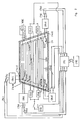
- FIG. 1 shows a window pane surrounded by a metallic frame, which is referred to below as the mass.
- the heating surface is used for the formation of at least two FM antennas.
- suitable pairs of terminals each of which is formed from the conductor part connection point (5a, b) and an adjacent earth point on the frame, can be Manufacture FM antennas whose signals are largely independent of each other.
- additional VHF antennas can be attached in the partial areas of the window that are not covered with conductors, the reception signals of which are also different from the other VHF antennas, particularly with regard to the interference to be avoided.
- the left half of the window above the heating surfaces is covered with a VHF monopoly (5c) which is designed as a parallel conductor that is combined at the connection point.
- the dimensions of this monopoly are chosen using the available space so that the average reception power takes on the best possible value. With the usual vehicle dimensions, the width of which in the VHF range is approximately half a wavelength, monopoles with a favorable length of a quarter wavelength can thus be realized.
- the distances from the frame and from the heating fields are set favorably according to known aspects.
- the space above the heating field in the right part of the window is used for the design of an LMK antenna according to known aspects.
- the heating field generally represents a mass for the LMK frequency range, just like the window frame, in terms of radio frequency.
- the dimensions according to the dimensions of the LMK antenna are set out in DOS-P 34 10 415.1 Viewpoints set.
Abstract
Description
Die Erfindung bezieht sich auf eine Mehrantennenanordnung mit mehreren Antennen für Antennendiversity vorzugsweise für den Empfang im Bereich der Meterwellen (UKW), z.B. im Kraftfahrzeug, gemäß dem Oberbegriff des Anspruches 1. Solche Mehrantennenanordnungen werden verwendet für den Empfang frequenzmodulierter Signale, wie z.B. des UKW-Rundfunks.The invention relates to a multi-antenna arrangement with a plurality of antennas for antenna diversity, preferably for reception in the range of the meter waves (VHF), e.g. in a motor vehicle, according to the preamble of
Für Antennendiversitysysteme, die eine deutliche Verbesserung des UKW-Empfangs im Kraftfahrzeug ermöglichen, sind mindestens zwei Antennen erforderlich.Antenna diversity systems that enable a significant improvement in VHF reception in the motor vehicle require at least two antennas.
Unter fahrzeugspezifischen Gesichtspunkten sind diese Antennen vorzugsweise so zu gestalten, daß sie in die Fahrzeugkarosserie integriert sind, was optimal in der Form von Scheibenantennen erfolgt. Neben der Frontscheibe, die aber in vielen Fahrzeugen wegen des dort vorhandenen hohen Störpegels durch die im Frontbereich der Fahrzeuge angeordneten Aggregate für die Realisierung von Antennen ausscheidet, ist die Fahrzeugheckscheibe geeignet zur Realisierung von Fahrzeugantennen.From a vehicle-specific point of view, these antennas should preferably be designed in such a way that they are integrated into the vehicle body, which takes place optimally in the form of window antennas. In addition to the windscreen, which is eliminated in many vehicles due to the high level of interference present there through the units arranged in the front area of the vehicles for the realization of antennas, the vehicle rear window is suitable for realizing vehicle antennas.
Die Realisierung von Fahrzeugantennen in der Hekcscheibe muß auf das dort vorhandene Heizfeld Rücksicht nehmen, dessen Ausführung und Abmessungen unter fahrzeugspezifischen und stilistischen Gesichtspunkten vorgegeben sind.The implementation of vehicle antennas in the rear window must take into account the heating field there, the design and dimensions of which are specified from a vehicle-specific and stylistic point of view.
Eine Anordnung für zwei Antennen in der Fahrzeugheckscheibe für die Anwendung in Diversitysystemen wird von EP 0065263 vorgeschlagen. Bei dieser Anordnung wird im vom Heizfeld nicht bedeckten Bereich der Scheibe eine Hauptantenne eingebaut.
Eine derartige Anordnung weist den Nachteil auf, daß das Diversitysystem auf zwei UKW-Antennen beschränkt ist. Sind die Signale von beiden Antennen gleichzeitig gestört, so ist der Empfang unbefriedigend und die empfundene Störung wird dadurch erheblich vergrößert, daß das Diversitysystem während dieser Zeit fortwährend zwischen den beiden Antennen umschaltet und das in der Praxis unvermeidbare Schaltgeräusch sich der Empfangsstörung zusätzlich überlagert. Dieser Fall ist in der Praxis häufig gegeben. Es ist deshalb notwendig, die Anzahl der für Antennendiversity zur Verfügung stehenden Antennen zu erhöhen. Andererseits ist die Verwendung zusätzlicher Antennen am Fahrzeug außerhalb des Fensters kostenintensiv.An arrangement for two antennas in the vehicle rear window for use in diversity systems is proposed by EP 0065263. With this arrangement, a main antenna is installed in the area of the pane not covered by the heating field.
Such an arrangement has the disadvantage that Diversity system is limited to two FM antennas. If the signals from both antennas are disturbed at the same time, the reception is unsatisfactory and the perceived interference is considerably increased by the fact that the diversity system continuously switches between the two antennas during this time and the switching noise that is inevitable in practice is also superimposed on the reception interference. This is often the case in practice. It is therefore necessary to increase the number of antennas available for antenna diversity. On the other hand, the use of additional antennas on the vehicle outside the window is expensive.
Der Erfindung liegt deshalb die Aufgabe zu Grunde, in einer Fensterscheibe eines Fahrzeugs unter Einbeziehung des Heizfelds mit vorgegebener Form eine Mehrantennenanordnung für Antennendiversity vorzugsweise für den Empfang im Bereich der Meterwellen (UKW) mit mehr als zwei Antennen auszubilden, wobei die mittlere Empfangsqualität mit jeder Einzelantenne möglichst gut ist und die Anzahl der Störungen, die in den Signalen der verschiedenen Antennen gleichzeitig auftreten, möglichst gering ist.The invention is therefore based on the object of forming a multi-antenna arrangement for antenna diversity, preferably for reception in the range of meter waves (VHF) with more than two antennas in a window pane of a vehicle, including the heating field with a predetermined shape, the average reception quality with each individual antenna is as good as possible and the number of interferences that occur simultaneously in the signals of the different antennas is as small as possible.
Diese Aufgabe wird erfindungsgemäß bei einer Diversityantennen-Anordnung der eingangs genannten Art durch die kennzeichnenden Merkmale des Anspruchs 1 gelöst. Eine HF-mäßige Entkopplung im Sinne des Anspruches 1 liegt vor, wenn die Empfangssignale der Antennen, insbesondere im Hinblick auf Empfangsstörungen, wie z.B. Einbrüche des HF-Pegels, unterschiedlich sind.This object is achieved according to the invention in a diversity antenna arrangement of the type mentioned at the outset by the characterizing features of
Erfindungsgemäße Ausführungsbeispiele sind in den angegebenen Zeichnungen dargestellt und werden im folgenden näher beschrieben. Im einzelnen zeigt:
- Fig. 1 Mehrantennenanordnung nach der Erfindung mit einer weiteren UKW-Antenne links oben im Fensterfeld, zwei aus dem Heizfeld gebildeten UKW-Antennen und einer Antenne für den LMK-Empfang (rechts oben).
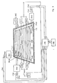
- Fig. 2 Mehrantennenanordnung nach der Erfindung wie Fig. 1, jedoch mit einer zusätzlichen aus dem Heizfeld gebildeten UKW-Antenne.
- Fig. 3 Mehrantennenanordnung wie in Fig. 1, jedoch mit einem Faltmonopol für die Ausbildung der weiteren UKW-Antenne (links oben).
- Fig. 4 Mehrantennenanordnung nach der Erfindung mit zwei weiteren UKW-Antennen unterhalb des Heizfeldes, von denen die eine als Faltmonopol (5c) und die andere als Drahtmonopol (5d) ausgeführt ist. Rechts unten im Fensterfeld ist beispielhaft eine Antenne für den LMK-Empfang angebracht.
- Fig. 5 Mehrantennenanordnung nach der Erfindung mit einer weiteren UKW-Antenne oberhalb des Heizfeldes, deren Antennenleiter (5c) auch als Teil einer LMK-Antenne verwendet ist.
- Fig. 1 multi-antenna arrangement according to the invention with a further FM antenna in the upper left corner of the window field, two FM antennas formed from the heating field and an antenna for LMK reception (top right).
- Fig. 2 multi-antenna arrangement according to the invention as Fig. 1, but with an additional FM antenna formed from the heating field.
- Fig. 3 multi-antenna arrangement as in Fig. 1, but with a folding monopoly for the formation of the further FM antenna (top left).
- Fig. 4 multi-antenna arrangement according to the invention with two further FM antennas below the heating field, one of which is designed as a folding monopoly (5c) and the other as a wire monopoly (5d). An antenna for LMK reception is attached as an example at the bottom right of the window field.
- Fig. 5 multi-antenna arrangement according to the invention with a further FM antenna above the heating field, the antenna conductor (5c) is also used as part of an LMK antenna.
In Fig. 1 ist eine von einem metallischen Rahmen, der im folgenden als Masse bezeichnet wird, umgebene Fensterscheibe dargestellt. Die Heizfläche wird für die Bildung von mindestens zwei UKW-Antennen herangezogen. Durch Wahl geeigneter Anschlußklemmenpaare, die jeweils aus dem Leiterteil-Anschlußpunkt (5a,b) und einem benachbarten Massepunkt auf dem Rahmen gebildet sind, lassen sich UKW-Antennen herstellen, deren Signale weitgehend unabhängig voneinander sind. In den nicht mit Leitern bedeckten Teilflächen des Fensters können erfindungsgemäß weitere UKW-Antennen angebracht werden, deren Empfangssignale ebenfalls insbesondere hinsichtlich der zu vermeidenden Störungen von den übrigen UKW-Antennen unterschiedlich sind. Im Beispiel der Fig. 1 ist die linke Hälfte des Fensters oberhalb der Heizflächen mit einem UKW-Monopol (5c) belegt, der als parallel geführte Leiter, die am Anschlußpunkt zusammengefaßt sind, ausgeführt ist. Die Abmessungen dieses Monopols sind unter Nutzung des zur Verfügung stehenden Raumes so gewählt, daß die mittlere Empfangsleistung einen möglichst guten Wert annimmt. Bei den üblichen Fahrzeugabmessungen, deren Breite im UKW-Bereich ungefähr eine halbe Wellenlänge beträgt, lassen sich somit Monopole mit einer günstigen Länge von einer viertel Wellenlänge realisieren. Die Abstände vom Rahmen und von den Heizfeldern werden nach bekannten Gesichtspunkten günstig eingestellt. Im Beispiel der Fig. 1 wird der Raum oberhalb des Heizfeldes im rechten Fensterteil für die Gestaltung einer LMK-Antenne nach bekannten Gesichtspunkten verwendet. Das Heizfeld stellt im allgemeinen für den LMK-Frequenzbereich, ebenso wie der Fensterrahmen, hochfrequenzmäßig eine Masse dar. Um für LMK einen guten Empfang zu gewährleisten, werden hinsichtlich der Dimensionierung der LMK-Antenne die Abmessungen nach den in DOS-P 34 10 415.1 dargelegten Gesichtspunkten eingestellt.1 shows a window pane surrounded by a metallic frame, which is referred to below as the mass. The heating surface is used for the formation of at least two FM antennas. By selecting suitable pairs of terminals, each of which is formed from the conductor part connection point (5a, b) and an adjacent earth point on the frame, can be Manufacture FM antennas whose signals are largely independent of each other. According to the invention, additional VHF antennas can be attached in the partial areas of the window that are not covered with conductors, the reception signals of which are also different from the other VHF antennas, particularly with regard to the interference to be avoided. In the example in FIG. 1, the left half of the window above the heating surfaces is covered with a VHF monopoly (5c) which is designed as a parallel conductor that is combined at the connection point. The dimensions of this monopoly are chosen using the available space so that the average reception power takes on the best possible value. With the usual vehicle dimensions, the width of which in the VHF range is approximately half a wavelength, monopoles with a favorable length of a quarter wavelength can thus be realized. The distances from the frame and from the heating fields are set favorably according to known aspects. In the example in FIG. 1, the space above the heating field in the right part of the window is used for the design of an LMK antenna according to known aspects. The heating field generally represents a mass for the LMK frequency range, just like the window frame, in terms of radio frequency. In order to ensure good reception for LMK, the dimensions according to the dimensions of the LMK antenna are set out in DOS-P 34 10 415.1 Viewpoints set.
Claims (13)
dadurch gekennzeichnet, daß
mindestens drei Diversityantennen vorhanden sind und mindestens zwei der Diversityantennen derartige stirnseitig angeordnete Leiterteile (4a, 4d; 4b, 4c) und zwischen diesen angeordnete, zu heizende Leiterteile (2a, 2b) und ein Klemmenpaar aufweisen, daß jedes Klemmenpaar einen Masseanschlußpunkt (14a, 14b) und einen Leiterteil-Anschlußpunkt (5a, 5b) aufweist, daß die Leiterteil-Anschlußpunkte (5a, 5b) der Diverstyantennen derart angeordnet sind, daß sie HF-mäßig weitgehend voneinander entkoppelt sind und daß in den Heizstromzuführungsleitungen HF-Leistung sperrende Elemente (6a-d) vorgesehen sind und in dem nicht mit Leitern bedeckten Flächenteil der Heckscheibe mindestens ein Antennenleiter mit einem Antennenleiter-Anschlußpunkt als Teil einer weiteren Antenne vorhanden ist und ein Anschlußklemmenpaar aus einem Masseanschluß (52,14c,14d) und dem Antennenleiter-Anschlußpunkt (5c,5d) gebildet ist und der Antennenleiter mit Anschlußklemmenpaar derart angeordnet ist, daß jede Diversityantenne HF-mäßig weitgehend von den anderen entkoppelt ist.1.Multi-antenna arrangement with several antennas for antenna diversity, preferably for reception in the area of the meter waves (VHF), for example for a motor vehicle, with a heating field arranged in the area of a window, for example a car rear window, with conductor parts arranged on the end face for supplying the heating current and with between these arranged conductor parts to be heated,
characterized in that
At least three diversity antennas are present and at least two of the diversity antennas have such conductor parts (4a, 4d; 4b, 4c) arranged on the end face and conductor parts (2a, 2b) arranged between them and to be heated and a pair of terminals that each pair of terminals has a ground connection point (14a, 14b ) and a conductor part connection point (5a, 5b), that the conductor part connection points (5a, 5b) of the diver antenna antennas are arranged in such a way that they are largely decoupled from each other in terms of HF and that RF power blocking elements (6a -d) are provided and in the area of the rear window which is not covered with conductors there is at least one antenna conductor with an antenna conductor connection point as part of another antenna and a pair of connecting terminals consisting of a ground connection (52, 14c, 14d) and the antenna conductor connection point (5c , 5d) is formed and the antenna conductor is arranged with a pair of terminals in such a way that each diversity tenne is largely decoupled from the others in terms of HF.
dadurch gekennzeichnet, daß
mindestens zwei der Diversityantennen aus einem Heizfeld (2) gebildet sind, dessen Heizstrom über nahezu senkrecht zu den Heizleitern angeordnete Sammelschienen (4a-d) zugeführt ist, und auf den Sammelschienen an unterschiedlichen Stellen mindestens zwei Anschlußpunkte (5a, b) gewählt sind, die zusammen mit zu diesen (5a, b) benachbarten Massepunkten (14a, b) auf dem Fensterrahmen (12) Anschlußklemmenpaare (5a, 14a, 5b, 14b) bilden und an diese Anschlußklemmenpaare jeweils ein weiterführrendes Netzwerk (8a, b) mit geeigneten Transformations- und/oder Verstärkereigenschaften angeschlossen ist, dessen Ausgang jeweils die Antennenanschlußstelle (7a, b) einer der Diversityantennen bildet, und in den Gleichstromzuführungen zu den Sammelschienen (4a-d) Netzwerke (6a-d) vorhanden sind, die für den Heiz-Gleichstrom durchlässig sind und die zwischen der jeweiligen Sammelschiene (4a-d) und Masse (12) eine verlustarme hochfrequenzmäßige Impedanz bilden.2. Multi-antenna arrangement according to claim 1,
characterized in that
At least two of the diversity antennas are formed from a heating field (2), the heating current of which is supplied via busbars (4a-d) arranged almost perpendicular to the heating conductors, and at least two connection points (5a, b) are selected on the busbars at different points together with these (5a, b) adjacent ground points (14a, b) on the window frame (12) form pairs of terminals (5a, 14a, 5b, 14b) and each of these pairs of terminals a further network (8a, b) with suitable transformation and / or amplifier properties are connected, the output of which forms the antenna connection point (7a, b) of one of the diversity antennas, and networks (6a-d) are present in the direct current feeds to the busbars (4a-d) which are permeable to the heating direct current are and which form a low-loss high-frequency impedance between the respective busbar (4a-d) and ground (12).
`` dadurch gekennzeichnet, daß
jede der weiteren Antennen ein an das Anschlußklemmenpaar angeschlossenes weiterführendes Netzwerk (8c, d) mit geeigneten Transformations- und/oder Verstärkereigenschaften enthält, dessen Ausgang jeweils die Antennenanschlußstelle (7c, d) einer der Diversityantennen bildet.3. Multi-antenna arrangement according to one of claims 1 to 2
`` characterized in that
each of the further antennas contains a further network (8c, d) with suitable transformation and / or amplifier properties connected to the pair of connecting terminals, the output of which forms the antenna connection point (7c, d) of one of the diversity antennas.
dadurch gekennzeichnet, daß
mindestens eine der weiteren Antennen einen flächenhaft ausgebildeten Antennenleiter in Form eines elektrischen Monopols mit für den Betriebsfrequenzbereich geeigneten Abmessungen besitzt.4. Multi-antenna arrangement according to one of claims 1 to 3
characterized in that
at least one of the further antennas has a planar antenna conductor in the form of an electrical monopole with dimensions suitable for the operating frequency range.
dadurch gekennzeichnet, daß
der flächenhaft ausgebildete Antennenleiter durch eine Reihe parallel geführter Drähte besteht, die mindestens an einer Stirnseite parallelgeschaltet sind und der Antennenleiter-Anschlußpunkt (5c) an einer solchen Stirnseite angeschlossen ist, oder durch eine Gitterstruktur nachgebildet ist.5. Multi-antenna arrangement according to claim 4
characterized in that
the flat antenna antenna consists of a series of parallel wires that are connected in parallel at least on one end face and the antenna conductor connection point (5c) is connected to such an end face, or is simulated by a lattice structure.
dadurch gekennzeichnet, daß
mindestens eine der weiteren Antennen einen Antennenleiter besitzt, der als Faltmonopol mit für den Betriebsfrequenzbereich geeigneten Abmessungen ausgebildet ist.6. Multi-antenna arrangement according to one of claims 1 to 3
characterized in that
at least one of the further antennas has an antenna conductor which is designed as a folding monopole with dimensions suitable for the operating frequency range.
dadurch gekennzeichnet, daß
mindestens eine der weiteren Antennen einen Antennenleiter besitzt, der als geradliniger linienförmiger Leiter mit für den Betriebsfrequenzbereich geeigneten Abmessungen ausgebildet ist.7. Multi-antenna arrangement according to one of claims 1 to 3
characterized in that
at least one of the further antennas has an antenna conductor which is designed as a straight line conductor with dimensions suitable for the operating frequency range.
dadurch gekennzeichnet, daß
die weiteren Antennen Antennenleiter mit unterschiedlichen Formen besitzen.8. Multi-antenna arrangement according to one of claims 1 to 7
characterized in that
the other antennas have antenna conductors with different shapes.
dadurch gekennzeichnet, daß
daß die Antennenleiter von zwei der weiteren Antennen oberhalb oder unterhalb des Heizfeldes angeordnet sind und eine im linken und die andere in der rechten Teilfläche angeordnet ist.9. Multi-antenna arrangement according to one of claims 1 to 8
characterized in that
that the antenna conductors of two of the further antennas are arranged above or below the heating field and one is arranged in the left and the other in the right partial area.
dadurch gekennzeichnet, daß die Anschlußpunkte (5a, b) und die hochfrequenzmäßigen Impedanzen der Netzwerke (6a-d) in den Gleichstromzuführungen zu den Sammelschienen (4a-d) geeignet gewählt sind, derart, daß die Anzahl der an allen Antennenanschlußstellen (7a, b) während der Fahrt gleichzeitig auftretenden Einbrüche der Empfangspegel möglichst klein ist.10. Multi-antenna arrangement according to one of claims 1 to 9
characterized in that the connection points (5a, b) and the high-frequency impedances of the networks (6a-d) in the direct-current feeds to the busbars (4a-d) are suitably selected such that the number of all antenna connection points (7a, b ) The reception level that occurs simultaneously while driving is as small as possible.
dadurch gekennzeichnet, daß die Heizleiterstruktur horizontal in etwa zwei flächengleiche Hälften unterteilt ist und auf den beiden für den Nutzfrequenzbereich bezüglich der Gleichstromzuführungen voneinander isolierten Teilheizfeldern (2a und 2b) zwei Anschlußpunkte (5a und 5b) vorhanden sind, die jeweils am Ende der jeweiligen Sammelschiene (4c, 4a) und untereinander diagonal entgegengesetzt angebracht sind.11. Multi-antenna arrangement according to one of claims 1 to 10
characterized in that the heating conductor structure is divided horizontally into approximately two halves of the same area and two connection points (5a and 5b) are provided on the two partial heating fields (2a and 2b) which are isolated from one another for the useful frequency range with regard to the direct current feeds, each of which is at the end of the respective busbar ( 4c, 4a) and diagonally opposite one another.
dadurch gekennzeichnet, daß
eine der weiteren Antennen auch für den Empfang von Lang-,Mittel-und Kurzwellen-Signalen verwendet ist und das weiterführende Netzwerk einen Signalweg mit Verstärker für LMK-Signale und einen getrennten Signalweg für UKW-Signale enthält und beide Signalwege eingangsseitig über eine Frequenzweiche miteinander verbunden sind und die Antennenanschlußstelle durch den Ausgang einer Frequenzweiche am Ausgang des weiterführenden Netzwerks gebildet ist.12. Multi-antenna arrangement according to one of claims 1 to 11
characterized in that
one of the further antennas is also used for the reception of long, medium and short wave signals and the further network contains a signal path with amplifier for LMK signals and a separate signal path for VHF signals and both signal paths are connected to one another on the input side via a crossover network are and the antenna connection point is formed by the output of a crossover at the output of the continuing network.
dadurch gekennzeichnet, daß
in einer nicht von Leitern bedeckten Teilfläche eine Antenne für den Empfang von Lang-,Mittel-und Kurzwellen-Signalen angebracht ist.13. Multi-antenna arrangement according to one of claims 1 to 11
characterized in that
an antenna for the reception of long, medium and short wave signals is attached in a partial area not covered by conductors.
Applications Claiming Priority (2)
| Application Number | Priority Date | Filing Date | Title |
|---|---|---|---|
| DE19873719692 DE3719692A1 (en) | 1987-06-12 | 1987-06-12 | MULTI-ANTENNA ARRANGEMENT FOR ANTENNA DIVERSITY IN A WINDOW WINDOW |
| DE3719692 | 1987-06-12 |
Publications (3)
| Publication Number | Publication Date |
|---|---|
| EP0297328A2 true EP0297328A2 (en) | 1989-01-04 |
| EP0297328A3 EP0297328A3 (en) | 1991-01-16 |
| EP0297328B1 EP0297328B1 (en) | 1995-05-03 |
Family
ID=6329590
Family Applications (1)
| Application Number | Title | Priority Date | Filing Date |
|---|---|---|---|
| EP88109330A Expired - Lifetime EP0297328B1 (en) | 1987-06-12 | 1988-06-11 | Arrangement of several antennas in a glass window to get antenna diversity |
Country Status (2)
| Country | Link |
|---|---|
| EP (1) | EP0297328B1 (en) |
| DE (2) | DE3719692A1 (en) |
Cited By (12)
| Publication number | Priority date | Publication date | Assignee | Title |
|---|---|---|---|---|
| EP0382895A1 (en) * | 1989-02-15 | 1990-08-22 | Robert Bosch Gmbh | Vehicle window antenna |
| EP0392969A1 (en) * | 1989-04-06 | 1990-10-17 | FUBA Hans Kolbe & Co | Window antenna system with an antenna signal amplifier |
| EP0418047A2 (en) * | 1989-09-14 | 1991-03-20 | Nippon Sheet Glass Co., Ltd. | Glass window antenna for motor vehicle |
| FR2660117A1 (en) * | 1990-03-23 | 1991-09-27 | Pizon Ernest | Antenna for a motor vehicle |
| EP0560677A1 (en) * | 1992-03-11 | 1993-09-15 | Saint-Gobain Vitrage International | Heatable laminates glass, containing resistance-wires in the thermoplastic interlayer |
| WO1995011530A1 (en) * | 1992-04-08 | 1995-04-27 | Wipac Group Limited | Vehicle antenna |
| EP0851528A2 (en) * | 1996-12-30 | 1998-07-01 | General Motors Corporation | Vehicle window antenna |
| WO1999014818A1 (en) * | 1997-09-12 | 1999-03-25 | Ppg Industries Ohio, Inc. | On-glass antenna system |
| US6400334B1 (en) | 1999-08-11 | 2002-06-04 | Fuba Automotive Gmbh & Co. Kg | Diversity antenna system for a motor vehicle |
| CN1127776C (en) * | 1995-09-28 | 2003-11-12 | 圣戈班玻璃制造公司 | Multicontact for antenna window |
| WO2007009831A1 (en) * | 2005-07-15 | 2007-01-25 | Robert Bosch Gmbh | Antenna array |
| CN107882492A (en) * | 2017-12-11 | 2018-04-06 | 重庆工业职业技术学院 | Millimeter wave antenna windowpane |
Families Citing this family (9)
| Publication number | Priority date | Publication date | Assignee | Title |
|---|---|---|---|---|
| DE3907493A1 (en) * | 1989-03-08 | 1990-09-20 | Lindenmeier Heinz | DISC ANTENNA WITH ANTENNA AMPLIFIER |
| DE3914424A1 (en) * | 1989-05-01 | 1990-12-13 | Lindenmeier Heinz | ANTENNA WITH VERTICAL STRUCTURE FOR TRAINING AN EXTENDED AREA CAPACITY |
| DE4019268A1 (en) * | 1990-03-10 | 1991-09-12 | Flachglas Ag | Vehicle double-glazing unit - including AM antenna element and combined heater and antenna element |
| DE4406240B4 (en) * | 1994-02-25 | 2004-02-19 | Heinz Prof. Dr.-Ing. Lindenmeier | Antenna arrangement on the rear window of a motor vehicle |
| DE19806834A1 (en) | 1997-03-22 | 1998-09-24 | Lindenmeier Heinz | Audio and television antenna for automobile |
| DE19823202C2 (en) * | 1998-05-25 | 2003-05-28 | Hirschmann Electronics Gmbh | Vehicle antenna device |
| DE10100812B4 (en) * | 2001-01-10 | 2011-09-29 | Heinz Lindenmeier | Diversity antenna on a dielectric surface in a vehicle body |
| DE10211341A1 (en) | 2002-03-14 | 2003-10-02 | Kathrein Werke Kg | Diversity antenna system for moving vehicles |
| DE102007011636A1 (en) | 2007-03-09 | 2008-09-11 | Lindenmeier, Heinz, Prof. Dr. Ing. | Antenna for radio reception with diversity function in a vehicle |
Citations (4)
| Publication number | Priority date | Publication date | Assignee | Title |
|---|---|---|---|---|
| EP0065263A1 (en) * | 1981-05-15 | 1982-11-24 | Asahi Glass Company Ltd. | Glass antenna system for an automobile |
| EP0155647A2 (en) * | 1984-03-21 | 1985-09-25 | Hans Kolbe & Co. | Antenna arrangement in the rear window of a car |
| US4608570A (en) * | 1982-11-18 | 1986-08-26 | Central Glass Company, Limited | Automotive window glass antenna |
| WO1987007770A1 (en) * | 1986-06-02 | 1987-12-17 | Hans Kolbe & Co. | Diversity aerial system |
Family Cites Families (2)
| Publication number | Priority date | Publication date | Assignee | Title |
|---|---|---|---|---|
| DE7010571U (en) * | 1970-03-21 | 1970-07-13 | Ver Glaswerke Gmbh | CAR LENS WITH BUILT-IN ANTENNA. |
| DE3630519A1 (en) * | 1986-09-08 | 1988-03-10 | Lindenmeier Heinz | Window pane antenna parallel to the window frame |
-
1987
- 1987-06-12 DE DE19873719692 patent/DE3719692A1/en active Granted
-
1988
- 1988-06-11 EP EP88109330A patent/EP0297328B1/en not_active Expired - Lifetime
- 1988-06-11 DE DE3853699T patent/DE3853699D1/en not_active Expired - Lifetime
Patent Citations (4)
| Publication number | Priority date | Publication date | Assignee | Title |
|---|---|---|---|---|
| EP0065263A1 (en) * | 1981-05-15 | 1982-11-24 | Asahi Glass Company Ltd. | Glass antenna system for an automobile |
| US4608570A (en) * | 1982-11-18 | 1986-08-26 | Central Glass Company, Limited | Automotive window glass antenna |
| EP0155647A2 (en) * | 1984-03-21 | 1985-09-25 | Hans Kolbe & Co. | Antenna arrangement in the rear window of a car |
| WO1987007770A1 (en) * | 1986-06-02 | 1987-12-17 | Hans Kolbe & Co. | Diversity aerial system |
Cited By (16)
| Publication number | Priority date | Publication date | Assignee | Title |
|---|---|---|---|---|
| EP0382895A1 (en) * | 1989-02-15 | 1990-08-22 | Robert Bosch Gmbh | Vehicle window antenna |
| EP0392969A1 (en) * | 1989-04-06 | 1990-10-17 | FUBA Hans Kolbe & Co | Window antenna system with an antenna signal amplifier |
| EP0418047A2 (en) * | 1989-09-14 | 1991-03-20 | Nippon Sheet Glass Co., Ltd. | Glass window antenna for motor vehicle |
| EP0418047A3 (en) * | 1989-09-14 | 1991-07-31 | Nippon Sheet Glass Co., Ltd. | Glass window antenna for motor vehicle |
| FR2660117A1 (en) * | 1990-03-23 | 1991-09-27 | Pizon Ernest | Antenna for a motor vehicle |
| EP0560677A1 (en) * | 1992-03-11 | 1993-09-15 | Saint-Gobain Vitrage International | Heatable laminates glass, containing resistance-wires in the thermoplastic interlayer |
| WO1995011530A1 (en) * | 1992-04-08 | 1995-04-27 | Wipac Group Limited | Vehicle antenna |
| CN1127776C (en) * | 1995-09-28 | 2003-11-12 | 圣戈班玻璃制造公司 | Multicontact for antenna window |
| EP0851528A3 (en) * | 1996-12-30 | 2000-02-09 | General Motors Corporation | Vehicle window antenna |
| EP0851528A2 (en) * | 1996-12-30 | 1998-07-01 | General Motors Corporation | Vehicle window antenna |
| WO1999014818A1 (en) * | 1997-09-12 | 1999-03-25 | Ppg Industries Ohio, Inc. | On-glass antenna system |
| US5959587A (en) * | 1997-09-12 | 1999-09-28 | Ppg Industries Ohio, Inc. | On the glass antenna system |
| US6400334B1 (en) | 1999-08-11 | 2002-06-04 | Fuba Automotive Gmbh & Co. Kg | Diversity antenna system for a motor vehicle |
| WO2007009831A1 (en) * | 2005-07-15 | 2007-01-25 | Robert Bosch Gmbh | Antenna array |
| CN107882492A (en) * | 2017-12-11 | 2018-04-06 | 重庆工业职业技术学院 | Millimeter wave antenna windowpane |
| CN107882492B (en) * | 2017-12-11 | 2023-10-27 | 重庆工业职业技术学院 | Millimeter wave antenna glass window |
Also Published As
| Publication number | Publication date |
|---|---|
| DE3719692C2 (en) | 1991-09-19 |
| EP0297328B1 (en) | 1995-05-03 |
| EP0297328A3 (en) | 1991-01-16 |
| DE3853699D1 (en) | 1995-06-08 |
| DE3719692A1 (en) | 1988-12-22 |
Similar Documents
| Publication | Publication Date | Title |
|---|---|---|
| DE3618452C2 (en) | Diversity antenna arrangement for receiving frequency-modulated signals in the rear window of a motor vehicle with a heating field located therein | |
| EP0297328A2 (en) | Arrangement of several antennas in a glass window to get antenna diversity | |
| EP0346591B1 (en) | Antenna for receiving meter waves,built in a window glass together with a heating of a motor vehicle | |
| EP0392969B1 (en) | Window antenna system with an antenna signal amplifier | |
| EP0155647B1 (en) | Antenna arrangement in the rear window of a car | |
| DE2914791C2 (en) | ||
| DE3914424C2 (en) | ||
| EP1076375B1 (en) | Diversity antenna for a diversity system in a vehicle | |
| DE69936903T2 (en) | Antenna for two frequencies for radio communication in the form of a microstrip antenna | |
| EP0514380B1 (en) | Antenna combination | |
| DE4023528C2 (en) | ||
| DE69913962T2 (en) | MORE BAND VEHICLE ANTENNA | |
| DE3907493A1 (en) | DISC ANTENNA WITH ANTENNA AMPLIFIER | |
| DE19541083B4 (en) | window antenna | |
| DE4447134A1 (en) | Slot antenna for vehicle windscreen | |
| DE4323239C2 (en) | Antenna structure for a motor vehicle rear window | |
| EP0580590B1 (en) | Aerial arrangement | |
| DE4034548C2 (en) | Automotive windshield antenna for frequencies above the high frequency range | |
| DE69924460T2 (en) | Vehicle-mounted antenna | |
| DE3619704A1 (en) | Antenna arrangement for diversity reception in the windowpane of a motor vehicle | |
| DE4423191B4 (en) | Window antenna with extreme bandwidth for motor vehicles | |
| DE19527304C1 (en) | Car window pane for reception of UHF radio waves | |
| DE4406240B4 (en) | Antenna arrangement on the rear window of a motor vehicle | |
| EP0224917B1 (en) | Arrangement for the transmission of directional radio-signals in two or more frequency bands | |
| DE102020209219A1 (en) | Window glass for a vehicle and window glass device for a vehicle |
Legal Events
| Date | Code | Title | Description |
|---|---|---|---|
| PUAI | Public reference made under article 153(3) epc to a published international application that has entered the european phase |
Free format text: ORIGINAL CODE: 0009012 |
|
| AK | Designated contracting states |
Kind code of ref document: A2 Designated state(s): DE FR GB IT SE |
|
| PUAL | Search report despatched |
Free format text: ORIGINAL CODE: 0009013 |
|
| AK | Designated contracting states |
Kind code of ref document: A3 Designated state(s): DE FR GB IT SE |
|
| 17P | Request for examination filed |
Effective date: 19910130 |
|
| RAP1 | Party data changed (applicant data changed or rights of an application transferred) |
Owner name: FUBA HANS KOLBE & CO |
|
| 17Q | First examination report despatched |
Effective date: 19930615 |
|
| GRAA | (expected) grant |
Free format text: ORIGINAL CODE: 0009210 |
|
| AK | Designated contracting states |
Kind code of ref document: B1 Designated state(s): DE FR GB IT SE |
|
| PG25 | Lapsed in a contracting state [announced via postgrant information from national office to epo] |
Ref country code: IT Free format text: LAPSE BECAUSE OF FAILURE TO SUBMIT A TRANSLATION OF THE DESCRIPTION OR TO PAY THE FEE WITHIN THE PRE;WARNING: LAPSES OF ITALIAN PATENTS WITH EFFECTIVE DATE BEFORE 2007 MAY HAVE OCCURRED AT ANY TIME BEFORE 2007. THE CORRECT EFFECTIVE DATE MAY BE DIFFERENT FROM THE ONE RECORDED.SCRIBED TIME-LIMIT Effective date: 19950503 |
|
| GBT | Gb: translation of ep patent filed (gb section 77(6)(a)/1977) |
Effective date: 19950428 |
|
| REF | Corresponds to: |
Ref document number: 3853699 Country of ref document: DE Date of ref document: 19950608 |
|
| ET | Fr: translation filed | ||
| RAP2 | Party data changed (patent owner data changed or rights of a patent transferred) |
Owner name: FUBA HANS KOLBE & CO |
|
| PLBE | No opposition filed within time limit |
Free format text: ORIGINAL CODE: 0009261 |
|
| STAA | Information on the status of an ep patent application or granted ep patent |
Free format text: STATUS: NO OPPOSITION FILED WITHIN TIME LIMIT |
|
| 26N | No opposition filed | ||
| REG | Reference to a national code |
Ref country code: GB Ref legal event code: 732E |
|
| REG | Reference to a national code |
Ref country code: GB Ref legal event code: IF02 |
|
| PGFP | Annual fee paid to national office [announced via postgrant information from national office to epo] |
Ref country code: SE Payment date: 20070607 Year of fee payment: 20 Ref country code: DE Payment date: 20070607 Year of fee payment: 20 |
|
| PGFP | Annual fee paid to national office [announced via postgrant information from national office to epo] |
Ref country code: GB Payment date: 20070606 Year of fee payment: 20 |
|
| PGFP | Annual fee paid to national office [announced via postgrant information from national office to epo] |
Ref country code: FR Payment date: 20070608 Year of fee payment: 20 |
|
| REG | Reference to a national code |
Ref country code: GB Ref legal event code: PE20 Expiry date: 20080610 |
|
| EUG | Se: european patent has lapsed | ||
| PG25 | Lapsed in a contracting state [announced via postgrant information from national office to epo] |
Ref country code: GB Free format text: LAPSE BECAUSE OF EXPIRATION OF PROTECTION Effective date: 20080610 |