EP0427619B1 - Heated laminated glass window for vehicles - Google Patents
Heated laminated glass window for vehicles Download PDFInfo
- Publication number
- EP0427619B1 EP0427619B1 EP90403148A EP90403148A EP0427619B1 EP 0427619 B1 EP0427619 B1 EP 0427619B1 EP 90403148 A EP90403148 A EP 90403148A EP 90403148 A EP90403148 A EP 90403148A EP 0427619 B1 EP0427619 B1 EP 0427619B1
- Authority
- EP
- European Patent Office
- Prior art keywords
- strips
- pane
- sheath
- conducting film
- layer
- Prior art date
- Legal status (The legal status is an assumption and is not a legal conclusion. Google has not performed a legal analysis and makes no representation as to the accuracy of the status listed.)
- Expired - Lifetime
Links
- 239000005340 laminated glass Substances 0.000 title 1
- 239000011888 foil Substances 0.000 claims description 40
- 239000011521 glass Substances 0.000 claims description 28
- 210000003298 dental enamel Anatomy 0.000 claims description 14
- 238000000034 method Methods 0.000 claims description 14
- 239000002184 metal Substances 0.000 claims description 10
- 229910052751 metal Inorganic materials 0.000 claims description 10
- 238000004519 manufacturing process Methods 0.000 claims description 7
- 229920001169 thermoplastic Polymers 0.000 claims description 7
- 239000004416 thermosoftening plastic Substances 0.000 claims description 7
- 239000000853 adhesive Substances 0.000 claims description 6
- 238000010438 heat treatment Methods 0.000 claims description 6
- 239000004033 plastic Substances 0.000 claims description 6
- 229920003023 plastic Polymers 0.000 claims description 6
- 230000001070 adhesive effect Effects 0.000 claims description 5
- 239000000463 material Substances 0.000 claims description 5
- RYGMFSIKBFXOCR-UHFFFAOYSA-N Copper Chemical compound [Cu] RYGMFSIKBFXOCR-UHFFFAOYSA-N 0.000 claims description 4
- 229910052802 copper Inorganic materials 0.000 claims description 4
- 239000010949 copper Substances 0.000 claims description 4
- 230000005611 electricity Effects 0.000 claims description 3
- 239000004642 Polyimide Substances 0.000 claims description 2
- 229920001721 polyimide Polymers 0.000 claims description 2
- 239000002313 adhesive film Substances 0.000 claims 1
- 239000010410 layer Substances 0.000 description 52
- 238000000151 deposition Methods 0.000 description 7
- 239000011229 interlayer Substances 0.000 description 5
- 230000008021 deposition Effects 0.000 description 4
- 239000003292 glue Substances 0.000 description 4
- NIXOWILDQLNWCW-UHFFFAOYSA-M Acrylate Chemical compound [O-]C(=O)C=C NIXOWILDQLNWCW-UHFFFAOYSA-M 0.000 description 3
- BQCADISMDOOEFD-UHFFFAOYSA-N Silver Chemical compound [Ag] BQCADISMDOOEFD-UHFFFAOYSA-N 0.000 description 3
- 229910052709 silver Inorganic materials 0.000 description 3
- 239000004332 silver Substances 0.000 description 3
- RRHGJUQNOFWUDK-UHFFFAOYSA-N Isoprene Chemical compound CC(=C)C=C RRHGJUQNOFWUDK-UHFFFAOYSA-N 0.000 description 2
- 239000004020 conductor Substances 0.000 description 2
- 230000008878 coupling Effects 0.000 description 2
- 238000010168 coupling process Methods 0.000 description 2
- 238000005859 coupling reaction Methods 0.000 description 2
- 230000006378 damage Effects 0.000 description 2
- 230000006866 deterioration Effects 0.000 description 2
- 229920002037 poly(vinyl butyral) polymer Polymers 0.000 description 2
- 229920001296 polysiloxane Polymers 0.000 description 2
- 238000007789 sealing Methods 0.000 description 2
- 239000007787 solid Substances 0.000 description 2
- ONIBWKKTOPOVIA-BYPYZUCNSA-N L-Proline Chemical compound OC(=O)[C@@H]1CCCN1 ONIBWKKTOPOVIA-BYPYZUCNSA-N 0.000 description 1
- 239000012790 adhesive layer Substances 0.000 description 1
- 238000005452 bending Methods 0.000 description 1
- 239000011248 coating agent Substances 0.000 description 1
- 238000000576 coating method Methods 0.000 description 1
- 150000001875 compounds Chemical class 0.000 description 1
- 238000010411 cooking Methods 0.000 description 1
- 238000005520 cutting process Methods 0.000 description 1
- 238000005137 deposition process Methods 0.000 description 1
- 239000013013 elastic material Substances 0.000 description 1
- 230000001788 irregular Effects 0.000 description 1
- 230000005923 long-lasting effect Effects 0.000 description 1
- 229910044991 metal oxide Inorganic materials 0.000 description 1
- 150000004706 metal oxides Chemical class 0.000 description 1
- -1 polysiloxanes Polymers 0.000 description 1
- 238000002360 preparation method Methods 0.000 description 1
- 239000011241 protective layer Substances 0.000 description 1
- 238000007650 screen-printing Methods 0.000 description 1
- 238000005476 soldering Methods 0.000 description 1
- 238000004544 sputter deposition Methods 0.000 description 1
- 230000003746 surface roughness Effects 0.000 description 1
- 239000012815 thermoplastic material Substances 0.000 description 1
Images


Classifications
-
- B—PERFORMING OPERATIONS; TRANSPORTING
- B32—LAYERED PRODUCTS
- B32B—LAYERED PRODUCTS, i.e. PRODUCTS BUILT-UP OF STRATA OF FLAT OR NON-FLAT, e.g. CELLULAR OR HONEYCOMB, FORM
- B32B17/00—Layered products essentially comprising sheet glass, or glass, slag, or like fibres
- B32B17/06—Layered products essentially comprising sheet glass, or glass, slag, or like fibres comprising glass as the main or only constituent of a layer, next to another layer of a specific material
- B32B17/10—Layered products essentially comprising sheet glass, or glass, slag, or like fibres comprising glass as the main or only constituent of a layer, next to another layer of a specific material of synthetic resin
- B32B17/10005—Layered products essentially comprising sheet glass, or glass, slag, or like fibres comprising glass as the main or only constituent of a layer, next to another layer of a specific material of synthetic resin laminated safety glass or glazing
- B32B17/10009—Layered products essentially comprising sheet glass, or glass, slag, or like fibres comprising glass as the main or only constituent of a layer, next to another layer of a specific material of synthetic resin laminated safety glass or glazing characterized by the number, the constitution or treatment of glass sheets
- B32B17/10036—Layered products essentially comprising sheet glass, or glass, slag, or like fibres comprising glass as the main or only constituent of a layer, next to another layer of a specific material of synthetic resin laminated safety glass or glazing characterized by the number, the constitution or treatment of glass sheets comprising two outer glass sheets
-
- B—PERFORMING OPERATIONS; TRANSPORTING
- B32—LAYERED PRODUCTS
- B32B—LAYERED PRODUCTS, i.e. PRODUCTS BUILT-UP OF STRATA OF FLAT OR NON-FLAT, e.g. CELLULAR OR HONEYCOMB, FORM
- B32B17/00—Layered products essentially comprising sheet glass, or glass, slag, or like fibres
- B32B17/06—Layered products essentially comprising sheet glass, or glass, slag, or like fibres comprising glass as the main or only constituent of a layer, next to another layer of a specific material
- B32B17/10—Layered products essentially comprising sheet glass, or glass, slag, or like fibres comprising glass as the main or only constituent of a layer, next to another layer of a specific material of synthetic resin
- B32B17/10005—Layered products essentially comprising sheet glass, or glass, slag, or like fibres comprising glass as the main or only constituent of a layer, next to another layer of a specific material of synthetic resin laminated safety glass or glazing
- B32B17/10165—Functional features of the laminated safety glass or glazing
- B32B17/10174—Coatings of a metallic or dielectric material on a constituent layer of glass or polymer
-
- B—PERFORMING OPERATIONS; TRANSPORTING
- B32—LAYERED PRODUCTS
- B32B—LAYERED PRODUCTS, i.e. PRODUCTS BUILT-UP OF STRATA OF FLAT OR NON-FLAT, e.g. CELLULAR OR HONEYCOMB, FORM
- B32B17/00—Layered products essentially comprising sheet glass, or glass, slag, or like fibres
- B32B17/06—Layered products essentially comprising sheet glass, or glass, slag, or like fibres comprising glass as the main or only constituent of a layer, next to another layer of a specific material
- B32B17/10—Layered products essentially comprising sheet glass, or glass, slag, or like fibres comprising glass as the main or only constituent of a layer, next to another layer of a specific material of synthetic resin
- B32B17/10005—Layered products essentially comprising sheet glass, or glass, slag, or like fibres comprising glass as the main or only constituent of a layer, next to another layer of a specific material of synthetic resin laminated safety glass or glazing
- B32B17/10165—Functional features of the laminated safety glass or glazing
- B32B17/10293—Edge features, e.g. inserts or holes
-
- B—PERFORMING OPERATIONS; TRANSPORTING
- B32—LAYERED PRODUCTS
- B32B—LAYERED PRODUCTS, i.e. PRODUCTS BUILT-UP OF STRATA OF FLAT OR NON-FLAT, e.g. CELLULAR OR HONEYCOMB, FORM
- B32B17/00—Layered products essentially comprising sheet glass, or glass, slag, or like fibres
- B32B17/06—Layered products essentially comprising sheet glass, or glass, slag, or like fibres comprising glass as the main or only constituent of a layer, next to another layer of a specific material
- B32B17/10—Layered products essentially comprising sheet glass, or glass, slag, or like fibres comprising glass as the main or only constituent of a layer, next to another layer of a specific material of synthetic resin
- B32B17/10005—Layered products essentially comprising sheet glass, or glass, slag, or like fibres comprising glass as the main or only constituent of a layer, next to another layer of a specific material of synthetic resin laminated safety glass or glazing
- B32B17/10165—Functional features of the laminated safety glass or glazing
- B32B17/10339—Specific parts of the laminated safety glass or glazing being colored or tinted
- B32B17/10348—Specific parts of the laminated safety glass or glazing being colored or tinted comprising an obscuration band
Definitions
- the invention relates to a method for manufacturing a laminated automobile glazing comprising two unitary glass sheets associated by a thermoplastic interlayer and being equipped with a thin and surface conductive layer acting as a heating resistor, glazing in which the one of the two sheets of glass constituting the laminated glazing comprises on its surface intended to be in contact with the thermoplastic interlayer, along two opposite sides, current leads made of an electrically conductive enamel on which is deposited the thin and superficial conductive layer, the glazing comprising strips of metal foil situated above the current leads and in electrical contact with the thin conductive layer, the strips of metallic foil emerging from the periphery of the laminated glazing.
- European patent application EP 0 322 756 A describes a process in which one begins by depositing on the outer glass sheet on the side in contact with the thermoplastic interlayer a frame based on opaque enamel, then where one deposits on this enamel the current leads made of an electrically conductive paste and finally only the thin conductive layer intended to heat the glazing.
- the current outputs are here also electrically connected to the enamelled current leads.
- the conductive layer assembly, current leads, copper strips is within the laminated glazing, that is to say between the two sheets of glass.
- This object is achieved by placing two of the metallic foil strips, each of these strips being provided in advance, on each of the current and thin conductive layers above each of the current leads obtained by baking a conductive enamel. at one of its ends of a sheath made of a tear-resistant plastic which leaves the laminated glazing, the sheath being coated in the zone intended to be found inside the laminated glazing with a layer of adhesive which ensures a solid and durable bond with the surface and thin conductive layer and the thermoplastic interlayer, by cutting the ends of the metal foil strips which are not sheathed, to the adequate length so that each of the foil strips penetrates substantially up to in the middle of the corresponding current supply, and by placing the two strips of foil corresponding to a current supply, one in the prol ongement of the other.
- a preferred variant of the invention provides that the metal foil strips are coated on one of their surfaces with a self-adhesive layer. This is intended to ensure contact between the foil and the thin and surface conductive layer and facilitates the manufacturing process.
- An electrically conductive glue can be used as the glue.
- the object of the invention was achieved even when the adhesive deposited on the foil was not electrically conductive. We can interpret this result by saying that at the time of assembly the pressure acts on the roughness of the enamel constituting the current leads and makes them pass through the glue which allows the entire surface to be used for the passage of current.
- each of the current leads which equip the two opposite edges of the glazing by making them come out on both sides so as to be able to equip each end with a terminal allowing the electrical connection.
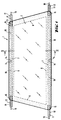
- Figures 1 and 2 show in detail the constitution of the heated laminated glazing 1. This is intended to constitute a windshield which will be mounted in the bay of an automobile body.
- the laminated glazing 1 consists of a unitary glass sheet 2 directed towards the outside of the vehicle, the unitary glass sheet 3 directed towards the interior of the vehicle, as well as the interlayer film 4 intended to associate the two sheets of glass which is based on a thermoplastic material, for example polyvinyl butyral.
- the glass sheet 2 is equipped at its periphery with a layer 6 in the form of a frame. This is based on an opaque enamel.
- the layer 6 is deposited on the glass sheet 2 when it is still flat by a silk screen screen printing process.
- the layer 6 is dried by passing it through an oven, enough so that the glass sheet 2 can be subjected to a new deposition by the same process. This deposition takes place along the upper and lower edges of the sheet 2 above the layer 6, these are the current leads 7 based on an electrically conductive enamel.
- the next phase of the process consists of cooking layers 6 and 7. This operation is carried out by making pass the glazing 2 through a through oven fitted with rollers. There, the glass sheet is brought to temperatures of 5 to 600 ° C.
- the deposition of the thin layers is preferably carried out under vacuum by the sputtering process assisted by a magnetic field or else by the same process in a reactive atmosphere. In the latter case, these are metallic compounds which are deposited in particular oxides. Such layer associations and their deposition process are available to those skilled in the art.
- the next phase of the process consists in depositing on the conductive layer 8 in the area of the current leads 7 strips of foil 10 which will be fixed on the glass sheet 2 so that they cannot slip during the end of the manufacturing process.
- the foil strips are equipped for this purpose with a thin layer 17 made of a self-adhesive material. It may not conduct electricity like glues based on isoprene or acrylate or it may be conductive and then it is acrylate.
- the foil strips 10 have a width of 8 to 16 mm and a thickness of 30 to 80 ⁇ m. They are preferably made of copper. They are placed on the glass sheet 2 with a length such that on each side a segment 11 5 to 10 cm long exceeds short sides of the sheet 2.
- the foil strips 10 are prepared in such a way, as shown in FIG. 3, that their ends are coated with a sheath 12 made of a tear-resistant plastic.
- the plastic sheath 12 is resistant and makes a long-lasting, watertight association with the metal strip.
- excellent results have been obtained with a plastic material based on polyimides.
- the sheath 12, in its part 13 in contact with the glass sheet is coated with a layer of adhesive 15 based on acrylate, silicone or polysiloxanes. This layer provides a solid bond between the sheath 12 and the layer 2 glazing. In this way, extension forces which could act on the section 11 are transmitted to the glass sheet and the foil strips are thus protected.
- the foil strips 10 are prepared at one of their ends by coating them with the sheath 12.
- the total length of these strips is such that they can be used on the widest windshield.
- a strip of foil 10 will be deposited on each of the current leads 7, the end opposite to the sheath 12 having been cut over a length such that each of the strips 10 can reach as far as the middle of the current supply 7.
- the fact of being able to prepare strips of foil all identical and to put them to length only by laying them allows a saving on their production cost.
- the fact of adjusting their length each time to the conditions of the glazing concerned is a very simple operation.
- the glass sheet 2 After the glass sheet 2 has undergone the previous preparation and has been fitted with the foil strips 10, it is assembled in the usual way with the other glass sheet 3 by means of a film for example made of polyvinyl butyral with a thickness of 0.76 mm.
- a film for example made of polyvinyl butyral with a thickness of 0.76 mm.
- the use of heat and pressure in particular in a suitable autoclave allows the previous assembly to become a laminated glazing.
- the ends 11 of the foil strips fitted with their sheath 12 are thin and have relative flexibility. They are likely as shown in Figure 5 to bypass the edge of the laminated glazing when for example the glazing 1 is mounted in a profile 16 of elastic material which allows it to be installed in the bay of a bodywork.
- the end 11 of the foil strip which is intended to make the electrical connection is equipped with a terminal 18 which can be used after mounting the windshield to make the electrical connection of the heated glazing.
Landscapes
- Joining Of Glass To Other Materials (AREA)
- Laminated Bodies (AREA)
- Surface Heating Bodies (AREA)
- Cosmetics (AREA)
Description
L'invention concerne un procédé de fabrication d'un vitrage automobiles feuilleté comportant deux feuilles de verre unitaires associées par une couche intercalaire thermoplastique et étant équipé d'une couche conductrice superficielle et mince jouant le rôle d'une résistance chauffante, vitrage dans lequel l'une des deux feuilles de verre constituant le vitrage feuilleté comporte sur sa surface destinée à être en contact avec la couche intercalaire thermoplastique, le long de deux côtés opposés, des amenées de courant faites d'un émail conducteur de l'électricité sur lesquelles est déposée la couche conductrice superficielle et mince, le vitrage comportant des bandes de clinquant métallique situées au-dessus des amenées de courant et en contact électrique avec la couche conductrice mince, les bandes de clinquant métallique sortant de la périphérie du vitrage feuilleté.The invention relates to a method for manufacturing a laminated automobile glazing comprising two unitary glass sheets associated by a thermoplastic interlayer and being equipped with a thin and surface conductive layer acting as a heating resistor, glazing in which the one of the two sheets of glass constituting the laminated glazing comprises on its surface intended to be in contact with the thermoplastic interlayer, along two opposite sides, current leads made of an electrically conductive enamel on which is deposited the thin and superficial conductive layer, the glazing comprising strips of metal foil situated above the current leads and in electrical contact with the thin conductive layer, the strips of metallic foil emerging from the periphery of the laminated glazing.
Des vitrages feuilletés chauffant électriquement équipés d'une couche mince transparente conductrice continue en contact électrique étroit avec des amenées de courant sont connus de plusieurs côtés. Dans le brevet US 4 668 270 on décrit par exemple des amenées de courant déposées sur la surface du verre et faites d'un émail conducteur de l'électricité sur lequel on vient déposer ensuite simultanément sur le verre et sur l'émail conducteur la couche mince transparente qui joue le rôle d'une résistance chauffante. Par ailleurs, on associe électriquement des connexions aux conducteurs pour permettre le raccordement à la source de courant.Electrically heated laminated glazings fitted with a thin transparent conductive layer in continuous electrical contact with current leads are known on several sides. In US Pat. No. 4,668,270, for example, there are described current leads deposited on the surface of the glass and made of an electrically conductive enamel on which the layer is then deposited simultaneously on the glass and on the conductive enamel. thin transparent which plays the role of a heating resistance. Furthermore, connections are electrically connected to the conductors to allow connection to the current source.
De même, il est connu de commencer à l'inverse par déposer la couche mince conductrice sur le verre puis seulement dans un deuxième temps d'appliquer sur le verre une pâte conductrice destinée à constituer les amenées de courant et enfin de la faire cuire (DE 35 43 694 A1).Likewise, it is known to start conversely by depositing the thin conductive layer on the glass and then only in a second step of applying on the glass a conductive paste intended to constitute the leads of current and finally to cook it (DE 35 43 694 A1).
La demande de brevet européenne EP 0 322 756 A décrit un procédé dans lequel on commence par déposer sur la feuille de verre extérieure du côté en contact avec l'intercalaire thermoplastique un cadre à base d'émail opaque, puis où l'on dépose sur cet émail les amenées de courant constituées d'une pâte conductrice de l'électricité et enfin seulement la couche mince conductrice destinée à chauffer le vitrage. Les sorties de courant sont ici également reliées électriquement aux amenées de courant émaillées.European patent application EP 0 322 756 A describes a process in which one begins by depositing on the outer glass sheet on the side in contact with the thermoplastic interlayer a frame based on opaque enamel, then where one deposits on this enamel the current leads made of an electrically conductive paste and finally only the thin conductive layer intended to heat the glazing. The current outputs are here also electrically connected to the enamelled current leads.
Il fait également partie de l'état de la technique de déposer dans une première phase la couche mince conductrice chauffante sur la surface du verre et de mettre en contact avec elle des bandes de clinquant qui sont liées à la couche mince grâce à une colle conductrice de l'électricité (US 3 612 745 B).It is also part of the state of the art to deposit in a first phase the heating conductive thin layer on the surface of the glass and to put in contact with it foil strips which are linked to the thin layer by means of a conductive adhesive. electricity (US 3,612,745 B).
Il est également connu, selon le document DE-A-2 533 364, ayant servi à délimiter le préambule de la revendication 1, de réaliser un vitrage feuilleté comportant une couche conductrice alimentée par des amenées de courant reliées directement à des bandes de cuivre débordant du vitrage.It is also known, according to document DE-A-2 533 364, having served to delimit the preamble of claim 1, to produce a laminated glazing comprising a conductive layer supplied by current leads directly connected to overflowing copper strips glazing.
Selon ce document, l'ensemble couche conductrice, amenées de courant, bandes de cuivre est au sein du vitrage feuilleté, c'est-à-dire entre les deux feuilles de verre.According to this document, the conductive layer assembly, current leads, copper strips is within the laminated glazing, that is to say between the two sheets of glass.
Tous les vitrages chauffants feuilletés équipés de couches minces conductrices transparentes de même que tous les procédés pour fabriquer de tels vitrages chauffants présentent de nombreux inconvénients spécifiques. Ainsi lorsque la couche mince est en contact avec des bandes de clinquant il est courant lorsqu'on met le vitrage en chauffe que l'on constate une détérioration de la couche mince ou même sa destruction complète au contact du clinquant, en effet ces contacts sont irréguliers et des pointes de tension ou de courant se produisent entre le clinquant et la couche. Lorsque les amenées de courant sont constituées d'un émail déposé sur le verre ou sur la couche il se présente des problèmes d'une autre nature liés à la nécessité de réaliser les contacts électriques par soudure directement sur la surface du verre ce qui produit une surépaisseur et nécessite de prévoir un trou dans la deuxième feuille de verre à ce niveau. Cela a pour conséquence non seulement une phase de travail supplémentaire mais entraîne des difficultés pour rendre le vitrage étanche en particulier lors du montage dans la carrosserie.All laminated heated glazing units fitted with thin transparent conductive layers as well as all the methods for manufacturing such heated glazing units have many specific drawbacks. Thus when the thin layer is in contact with foil strips it is common when the glazing is heated that there is a deterioration of the thin layer or even its complete destruction in contact with the foil, in fact these contacts are irregular and voltage or current spikes occur between the foil and the layer. When the current leads consist of an enamel deposited on the glass or on the layer, there are problems of another nature related to the need to make the electrical contacts by soldering directly on the surface of the glass which produces a extra thickness and requires providing a hole in the second glass sheet at this level. This not only results in an additional working phase but also causes difficulties in sealing the glazing, in particular during mounting in the bodywork.
L'invention se donne pour mission de fournir un procédé de fabrication d'un vitrage automobile du type mentionné plus haut dans lequel d'une part le couplage du courant électrique et de la couche conductrice par l'intermédiaire des amenées de courant se fait de manière régulière sans risque de détérioration ou de destruction de la couche par suite de pointes de tension ou de courant et dans lequel d'autre part la connexion entre les amenées de courant à l'intérieur du vitrage et les conducteurs électriques en dehors du vitrage s'effectue en dehors de lui et sans perturber l'étanchéité du vitrage à sa périphérie et sans entraîner de difficultés lors du montage.The object of the invention is to provide a method for manufacturing an automotive glazing of the type mentioned above in which, on the one hand, the coupling of the electric current and the conductive layer by means of the current leads is made regularly without risk of deterioration or destruction of the layer as a result of voltage or current spikes and in which, on the other hand, the connection between the current leads inside the glazing and the electrical conductors outside the glazing s 'performs outside of it and without disturbing the sealing of the glazing at its periphery and without causing difficulties during assembly.
Ce but est atteint en disposant sur la couche conductrice superficielle et mince, au-dessus de chacune des amenées de courant obtenues par la cuisson d'un émail conducteur, deux des bandes de clinquant métallique, chacune de ces bandes étant équipée à l'avance à l'une de ses extrémités d'une gaine constituée d'un plastique résistant à la déchirure qui sort du vitrage feuilleté, la gaine étant revêtue dans la zone destinée à se retrouver à l'intérieur du vitrage feuilleté d'une couche de colle qui assure une liaison solide et durable avec la couche conductrice superficielle et mince et la couche intercalaire thermoplastique, en coupant les extrémités des bandes de clinquant métallique qui sont dépourvues de gaine, à la longueur adéquate pour que chacune des bandes de clinquant pénètre sensiblement jusqu'au milieu de l'amenée de courant correspondante, et en disposant les deux bandes de clinquant correspondantes à une amenée de courant, l'une dans le prolongement de l'autre.This object is achieved by placing two of the metallic foil strips, each of these strips being provided in advance, on each of the current and thin conductive layers above each of the current leads obtained by baking a conductive enamel. at one of its ends of a sheath made of a tear-resistant plastic which leaves the laminated glazing, the sheath being coated in the zone intended to be found inside the laminated glazing with a layer of adhesive which ensures a solid and durable bond with the surface and thin conductive layer and the thermoplastic interlayer, by cutting the ends of the metal foil strips which are not sheathed, to the adequate length so that each of the foil strips penetrates substantially up to in the middle of the corresponding current supply, and by placing the two strips of foil corresponding to a current supply, one in the prol ongement of the other.
Grâce à l'utilisation d'éléments de clinquant métallique avec une épaisseur de 30 à 100 µm et au dépôt d'amenées de courant faites d'un émail conducteur entre lesquelles la couche mince conductrice a été déposée, on atteint une régularité dans le couplage électrique entre la couche conductrice et les amenées de courant qui est surprenante et cela sans que des surtensions ou des pointes dans l'intensité du courant ne se produisent. Du fait qu'entre les amenées de courant constituées d'un émail conducteur et la couche mince conductrice un contact intime s'établit naturellement sur toute la surface de l'amenée de courant, il n'est pas nécessaire qu'un contact aussi étroit soit réalisé entre la bande de clinquant et la couche mince conductrice. Au contraire, on a pu constater que le but de l'invention était atteint même lorsque le contact entre ces deux dernières surfaces n'était pas parfaitement continu. C'est ainsi qu'il suffit par exemple que le contact mécanique entre la bande de clinquant et la couche mince soit réalisé naturellement lors du passage à l'autoclave du vitrage terminé avec une pression de plus de 10 atmosphères pour que la liaison électrique soit assurée dans de bonnes conditions. Il semble que ce soit la rugosité de surface naturelle des amenées de courant qui assure un contact ponctuel multiple avec la bande métallique, contact qui suffit à permettre le passage du courant entre les amenées de courant à base d'émail conducteur et la couche conductrice dans des conditions particulièrement régulières.Thanks to the use of metallic foil elements with a thickness of 30 to 100 μm and to the deposit of current leads made of a conductive enamel between which the thin conductive layer has been deposited, a regularity is achieved in the coupling. electric between the conductive layer and the current leads which is surprising and this without overvoltages or spikes in the intensity of the current occurring. Because an intimate contact between the current leads consisting of a conductive enamel and the thin conductive layer naturally occurs over the entire surface of the current lead, it is not necessary that such close contact is made between the foil strip and the thin conductive layer. On the contrary, it has been observed that the object of the invention was achieved even when the contact between these last two surfaces was not perfectly continuous. It is thus sufficient, for example, that the mechanical contact between the foil strip and the thin layer is achieved naturally during the autoclave passage of the glazing finished with a pressure of more than 10 atmospheres so that the electrical connection is ensured in good conditions. It seems that it is the natural surface roughness of the current leads which ensures multiple point contact with the metal strip, contact which is sufficient to allow the passage of current between the current leads based on conductive enamel and the conductive layer in particularly regular conditions.
Une variante préférée de l'invention prévoit que les bandes de clinquant métallique soient revêtues sur l'une de leurs surfaces d'une couche auto-collante. Celle-ci est destinée à assurer un contact entre le clinquant et la couche conductrice superficielle et mince et facilite le processus de fabrication. On peut utiliser comme colle une colle conductrice de l'électricité. De manière inattendue on a constaté que le but de l'invention était atteint même lorsque la colle déposée sur le clinquant n'était pas conductrice de l'électricité. On peut interpréter ce résultat en disant qu'au moment de l'assemblage la pression agit sur les rugosités de l'émail constituant les amenées de courant et leur fait traverser la colle ce qui permet à toute la surface de servir au passage du courant.A preferred variant of the invention provides that the metal foil strips are coated on one of their surfaces with a self-adhesive layer. This is intended to ensure contact between the foil and the thin and surface conductive layer and facilitates the manufacturing process. An electrically conductive glue can be used as the glue. Unexpectedly, it was found that the object of the invention was achieved even when the adhesive deposited on the foil was not electrically conductive. We can interpret this result by saying that at the time of assembly the pressure acts on the roughness of the enamel constituting the current leads and makes them pass through the glue which allows the entire surface to be used for the passage of current.
On dispose des éléments de clinquant sur chacune des amenées de courant qui équipe les deux bords opposés du vitrage en les faisant sortir des deux côtés de manière à pouvoir équiper chaque extrémité d'une cosse permettant le raccordement électrique. On obtient ainsi que chacune des connexions ne soit responsable que du passage de la moitié du courant et que l'on puisse de la sorte, toutes choses égales par ailleurs, en diviser la section par deux.There are foil elements on each of the current leads which equip the two opposite edges of the glazing by making them come out on both sides so as to be able to equip each end with a terminal allowing the electrical connection. We thus obtain that each of the connections is only responsible for the passage of half the current and that we can in this way, all other things being equal, divide the section by two.
D'autres caractéristiques et avantages de l'invention apparaîtront à la lecture de la description et des exemples préférés ainsi que des figures qui suivent.Other characteristics and advantages of the invention will appear on reading the description and the preferred examples as well as the figures which follow.
Les figures présentent successivement :
- figure 1 : un vitrage feuilleté chauffant correspondant à l'invention,
- figure 2 : une coupe agrandie le long de la ligne II/II de la figure 1,
- figure 3 : une bande de clinquant préparée pour être utilisée dans un vitrage feuilleté chauffant,
- figure 4 : une coupe le long de la ligne IV/IV de la figure 3,
- figure 5 : une coupe partielle d'un vitrage chauffant dans son joint en élastomère dans la région des connexions électriques.
- FIG. 1: a heated laminated glazing corresponding to the invention,
- FIG. 2: an enlarged section along line II / II of FIG. 1,
- FIG. 3: a strip of foil prepared for use in a heated laminated glazing,
- FIG. 4: a section along the line IV / IV of FIG. 3,
- Figure 5: a partial section of a heated glazing in its elastomeric seal in the region of electrical connections.
Les figures 1 et 2 montrent en détail la constitution du vitrage feuilleté chauffant 1. Celui-ci est destiné à constituer un pare-brise qui sera monté dans la baie d'une carrosserie automobile. Le vitrage feuilleté 1 se compose d'une feuille de verre unitaire 2 dirigée vers l'extérieur du véhicule, de la feuille de verre unitaire 3 dirigée vers l'intérieur du véhicule, ainsi que du film intercalaire 4 destiné à associer les deux feuilles de verre qui est à base d'une matière thermoplastique par exemple de polyvinylbutyral.Figures 1 and 2 show in detail the constitution of the heated laminated glazing 1. This is intended to constitute a windshield which will be mounted in the bay of an automobile body. The laminated glazing 1 consists of a unitary glass sheet 2 directed towards the outside of the vehicle, the unitary glass sheet 3 directed towards the interior of the vehicle, as well as the
La feuille de verre 2 est équipée à sa périphérie d'une couche 6 en forme de cadre. Celle-ci est à base d'un émail opaque. La couche 6 est déposée sur la feuille de verre 2 lorsqu'elle est encore plane par un procédé de sérigraphie à l'écran de soie. A la fin du dépôt la couche 6 est séchée par passage dans une étuve, suffisamment pour que la feuille de verre 2 puisse être soumise à un nouveau dépôt par le même procédé. Ce dépôt s'effectue le long des bords supérieurs et inférieurs de la feuille 2 au-dessus de la couche 6, il s'agit des amenées de courant 7 à base d'un émail conducteur de l'électricité.The glass sheet 2 is equipped at its periphery with a
La phase suivante du procédé consiste à cuire les couches 6 et 7. Cette opération s'effectue en faisant transiter le vitrage 2 dans un four traversant équipé de rouleaux. Là, la feuille de verre est portée à des températures de 5 à 600°C.The next phase of the process consists of
Enfin, dans la phase suivante les deux feuilles de verre 3 et 2, cette dernière équipée des couches 6 et 7, sont assemblées et toutes deux subissent un bombage commun. A l'issue de cette opération, la feuille 2 est équipée sur sa surface comportant les couches 6 et 7 de la couche mince conductrice superficielle et mince 8 destinée à jouer le rôle de résistance chauffante. Cette couche 8 est déposée par les techniques connues habituelles. Elle consiste en plusieurs couches minces élémentaires comportant une couche d'argent conductrice. Habituellement, la couche d'argent est prise en sandwich entre plusieurs autres couches, en particulier les couches d'oxyde métallique qui jouent le rôle de couches d'accrochage et/ou de couches de protection ainsi que des couches interférentielles qui jouent un rôle d'anti-reflet pour la couche d'argent. Le dépôt des couches minces se fait de préférence sous vide par le procédé de pulvérisation cathodique assistée par un champ magnétique ou bien par le même procédé en atmosphère réactive. Dans ce dernier cas ce sont des composés métalliques qui sont déposés en particulier des oxydes. De telles associations de couches ainsi que leur procédé de dépôt sont à la disposition de l'homme de l'art.Finally, in the next phase, the two glass sheets 3 and 2, the latter fitted with
La phase suivante du procédé consiste à déposer sur la couche conductrice 8 dans la zone des amenées de courant 7 des bandes de clinquant 10 qui seront fixées sur la feuille de verre 2 de manière à ce qu'elles ne puissent pas glisser pendant la fin du processus de fabrication. C'est pourquoi les bandes de clinquant sont équipées dans ce but d'une couche mince 17 faite d'un matériau auto-collant. Celui-ci peut ne pas être conducteur de l'électricité comme les colles à base d'isoprène ou d'acrylate ou bien il peut être conducteur et alors il s'agit d'acrylate. Les bandes de clinquant 10 ont une largeur de 8 à 16 mm et une épaisseur de 30 à 80 µm. Elles sont de préférence en cuivre. On les dépose sur la feuille de verre 2 avec une longueur telle que de chaque côté un segment 11 long de 5 à 10 cm dépasse des petits côtés de la feuille 2.The next phase of the process consists in depositing on the
Les bandes de clinquant 10 sont préparées de telle manière, comme on l'a représenté figure 3, que leurs extrémités sont revêtues d'une gaine 12 faite d'un plastique résistant à la déchirure. La gaine de plastique 12 est résistante et elle fait avec la bande métallique une association de longue durée étanche. Comme matériau adapté à constituer la gaine 12 d'excellents résultats ont été obtenus avec une matière plastique à base de polyimides. Du côté extérieur, la gaine 12, dans sa partie 13 en contact avec la feuille de verre, est revêtue d'une couche de colle 15 à base d'acrylate, de silicone ou de polysiloxanes. Cette couche assure une liaison solide entre la gaine 12 et le vitrage à couche 2. De cette manière, des forces d'extension qui pourraient agir sur la section 11 sont transmises à la feuille de verre et les bandes de clinquant sont ainsi protégées.The foil strips 10 are prepared in such a way, as shown in FIG. 3, that their ends are coated with a
Les bandes de clinquant 10 sont préparées à une de leurs extrémités en les revêtant de la gaine 12. La longueur totale de ces bandes est telle qu'elles puissent être utilisées sur le pare-brise le plus large. Comme on le voit sur la figure 1 on déposera sur chacune des amenées de courant 7 une bande de clinquant 10 dont l'extrémité opposée à la gaine 12 aura été coupée sur une longueur telle que chacune des bandes 10 puisse parvenir jusque sensiblement au milieu de l'amenée de courant 7. Il n'est pas nécessaire que les deux extrémités 14 des bandes de clinquant se touchent, au contraire il est préférable, comme on l'a représenté figure 1 qu'elles s'écartent légèrement l'une de l'autre. Le fait de pouvoir préparer des bandes de clinquant toutes identiques et de les mettre à longueur seulement en les posant permet une économie sur leur coût de production. Le fait d'ajuster à chaque fois leur longueur aux conditions du vitrage concerné est une opération très simple.The foil strips 10 are prepared at one of their ends by coating them with the
Après que la feuille de verre 2 ait subi la préparation précédente et qu'elle ait été équipée des bandes de clinquant 10 elle est assemblée de la manière habituelle avec l'autre feuille de verre 3 par l'intermédiaire d'un film par exemple en polyvinylbutyral d'une épaisseur de 0,76 mm. L'utilisation de chaleur et de pression en particulier dans un autoclave adapté permet à l'assemblage précédent de devenir un vitrage feuilleté.After the glass sheet 2 has undergone the previous preparation and has been fitted with the foil strips 10, it is assembled in the usual way with the other glass sheet 3 by means of a film for example made of polyvinyl butyral with a thickness of 0.76 mm. The use of heat and pressure in particular in a suitable autoclave allows the previous assembly to become a laminated glazing.
Les extrémités 11 des bandes de clinquant équipées de leur gaine 12 sont minces et possèdent une relative flexibilité. Ils sont susceptibles comme on l'a représenté figure 5 de contourner le bord du vitrage feuilleté quand par exemple le vitrage 1 est monté dans un profilé 16 en matériau élastique qui lui permet d'être installé dans la baie d'une carrosserie. L'extrémité 11 de la bande de clinquant qui est destiné à réaliser la connexion électrique est équipée d'une cosse 18 qui pourra servir après montage du pare-brise à faire le branchement électrique du vitrage chauffant.The ends 11 of the foil strips fitted with their
Claims (4)
- Method intended for the production of a laminated automobile pane (1), comprising two single glass sheets (2, 3) associated together by a thermoplastics intermediate layer (4) and being equipped with a thin surface conducting film (8) fulfilling the function of a heating resistor, in which pane the one (2) of the two glass sheets (2, 3) constituting the laminated pane (1) comprises, on its face intended to be in contact with the thermoplastics intermediate layer (4), along two opposite sides, electricity supply leads (7) made of an electrically conducting enamel, onto which there is deposited the thin surface conducting film (8), the pane comprising strips of metal foil (10) situated over the supply leads (7) and in electrical contact with the thin conducting film (8), said strips of metal foil (10) emerging from the periphery of the laminated pane (1), characterized in that there are disposed, on the thin surface conducting film (8) over each of the electrical supply leads (7), two of said metal foil strips (10), each of these strips being equipped in advance at the one of its ends with a sheath (12) constituted of a tear-resistant plastics material which emerges from the laminated pane (1), said sheath (12) being coated, in the zone intended to be situated inside the laminated pane (1), with a layer of adhesive (15) which assures a firm and durable bond with the thin surface conducting film (8) and the intermediate thermoplastics layer (4), in that the ends of the metal foil strips (10) which are without any sheath (12) are cut to a length sufficient for each of the foil strips (10) to penetrate substantially to the middle of the corresponding electrical supply lead (7), and in that the two foil strips (10) corresponding to one electrical supply lead (7) are disposed the one in the continuation of the other.
- Method according to Claim 1, characterized in that the foil strips (10) are provided, on the side which rests on the thin surface conducting film (8), with a self-adhesive film (17) which enables the foil strips to be fixed to the thin surface conducting film (8).
- Method according to one of Claims 1 or 2, characterized in that there is used as sheath (12), surrounding the one of the ends of the foil strips (10), a sheath (12) made of a plastics material based upon polyimide.
- Heating automobile pane constructed according to one of Claims 1 to 3, characterized in that the metal foil strips (10) are of copper having a width of 8 to 15 mm and a thickness of 30 to 100 µm.
Applications Claiming Priority (2)
| Application Number | Priority Date | Filing Date | Title |
|---|---|---|---|
| DE3937346A DE3937346A1 (en) | 1989-11-09 | 1989-11-09 | ELECTRICALLY HEATED CAR GLASS PANEL MADE OF COMPOSITE GLASS |
| DE3937346 | 1989-11-09 |
Publications (3)
| Publication Number | Publication Date |
|---|---|
| EP0427619A2 EP0427619A2 (en) | 1991-05-15 |
| EP0427619A3 EP0427619A3 (en) | 1992-02-26 |
| EP0427619B1 true EP0427619B1 (en) | 1994-11-09 |
Family
ID=6393215
Family Applications (1)
| Application Number | Title | Priority Date | Filing Date |
|---|---|---|---|
| EP90403148A Expired - Lifetime EP0427619B1 (en) | 1989-11-09 | 1990-11-07 | Heated laminated glass window for vehicles |
Country Status (7)
| Country | Link |
|---|---|
| US (1) | US5099104A (en) |
| EP (1) | EP0427619B1 (en) |
| JP (1) | JP2950602B2 (en) |
| CA (1) | CA2029684C (en) |
| DE (2) | DE3937346A1 (en) |
| DK (1) | DK0427619T3 (en) |
| ES (1) | ES2066170T3 (en) |
Cited By (1)
| Publication number | Priority date | Publication date | Assignee | Title |
|---|---|---|---|---|
| CN105247953A (en) * | 2013-02-22 | 2016-01-13 | Lg化学株式会社 | Heating element and method for manufacturing same |
Families Citing this family (49)
| Publication number | Priority date | Publication date | Assignee | Title |
|---|---|---|---|---|
| DE4126533A1 (en) * | 1991-08-10 | 1993-02-11 | Ver Glaswerke Gmbh | METHOD FOR CONTACTING ELECTRICALLY HEATABLE GLASS DISCS WITH TRANSPARENT HEATING RESISTANT LAYERS |
| DE4235063A1 (en) * | 1992-10-17 | 1994-04-21 | Ver Glaswerke Gmbh | Car glass made of laminated glass with wires embedded in the intermediate layer and a connection cable |
| FR2700422B1 (en) * | 1993-01-12 | 1995-03-03 | Saint Gobain Vitrage Int | Connection of glazing to an electrical power source. |
| KR950701605A (en) * | 1993-03-26 | 1995-04-28 | 에스. 르 가게레제. | Method for fabricating laminated enamelled glazing glazing, and enamelled composition used the efor |
| FR2703043B1 (en) * | 1993-03-26 | 1995-10-20 | Saint Gobain Vitrage Int | Composition for glazing glass substrates, application to laminated glazing and products obtained. |
| DE4333655C2 (en) * | 1993-10-02 | 2002-11-14 | Bayerische Motoren Werke Ag | Heater for cover windows of motor vehicle headlights |
| FR2717339B3 (en) † | 1994-03-08 | 1996-05-24 | Saint Gobain Vitrage | Sealing of an electrical connection of a glazing. |
| GB9425986D0 (en) | 1994-12-22 | 1995-02-22 | Pilkington Glass Ltd | Electrically heated window |
| FR2730724B1 (en) * | 1995-02-21 | 1997-04-04 | Saint Gobain Vitrage | GLASS FOR MOTOR VEHICLE |
| US5824993A (en) * | 1995-05-04 | 1998-10-20 | Ford Motor Company | Arrangement for heating an automobile glazing unit |
| US5911899A (en) * | 1995-06-15 | 1999-06-15 | Mitsui Chemicals, Inc. | Corrosion-proof transparent heater panels and preparation process thereof |
| US5653903A (en) * | 1995-06-27 | 1997-08-05 | Ppg Industries, Inc. | L-shaped heating element with radiused end for a windshield |
| DE19541609C2 (en) * | 1995-11-08 | 1998-02-19 | Sekurit Saint Gobain Deutsch | Electrically heated laminated glass for motor vehicles |
| US5886321A (en) * | 1996-12-19 | 1999-03-23 | Ppg Industries, Inc. | Arrangement for heating the wiper rest area of a vehicle windshield |
| US6144017A (en) * | 1997-03-19 | 2000-11-07 | Libbey-Owens-Ford Co. | Condensation control system for heated insulating glass units |
| US6180921B1 (en) * | 1999-10-08 | 2001-01-30 | Visteon Global Technologies, Inc. | Windshield heating device |
| DE19958363A1 (en) * | 1999-12-03 | 2001-06-28 | Wet Automotive Systems Ag | Heating element for heating motor vehicle seats has a ribbon cable, a heat conductor connected to one or more conductors in the ribbon cable in an intermediate area set apart from the ends of the ribbon cable. |
| DE10030066B4 (en) * | 2000-06-19 | 2006-04-13 | Guardian Automotive-Europe S.A. Zone Industrielle Potaschberg | Electrical connection unit |
| DE10126869A1 (en) * | 2001-06-01 | 2002-12-19 | Saint Gobain Sekurit D Gmbh | Electrically heated disc |
| DE10160806A1 (en) * | 2001-12-11 | 2003-06-26 | Saint Gobain Sekurit D Gmbh | Heating disc with an electrically conductive surface coating |
| US6870134B2 (en) * | 2002-02-01 | 2005-03-22 | Centre Luxembourgeois De Recherches Pour Le Verre Et La Ceramique S.A. (C.R.V.C.) | Heatable vehicle windshield with bus bars including braided and printed portions |
| US7993266B2 (en) * | 2002-04-26 | 2011-08-09 | Lawrence Livermore National Security, Llc | Early detection of contagious diseases |
| CA2435164A1 (en) * | 2002-07-15 | 2004-01-15 | Magna Donnelly Mirrors North America L.L.C. | Resizeable mirror heating element and vehicular mirror assembly incorporating the same |
| US6791065B2 (en) * | 2002-07-24 | 2004-09-14 | Ppg Industries Ohio, Inc. | Edge sealing of a laminated transparency |
| US6995339B2 (en) * | 2002-09-18 | 2006-02-07 | Ppg Industries Ohio, Inc. | Heatable wiper rest area for a transparency |
| US7159756B2 (en) * | 2003-08-29 | 2007-01-09 | Ppg Industries Ohio, Inc. | Method of soldering and solder compositions |
| DE10360255A1 (en) * | 2003-12-20 | 2005-07-21 | Volkswagen Ag | Heated windscreen at vehicle, comprising connecting plug positioned directly at edge of pane |
| US7200921B2 (en) * | 2005-02-04 | 2007-04-10 | Automotive Components Holdings, Llc | Method of manufacturing a heated windshield |
| US8299400B2 (en) * | 2005-08-04 | 2012-10-30 | Guardian Industries Corp. | Heatable vehicle window utilizing silver inclusive epoxy electrical connection and method of making same |
| FR2927218B1 (en) * | 2008-02-06 | 2010-03-05 | Hydromecanique & Frottement | METHOD OF MANUFACTURING A HEATING ELEMENT BY DEPOSITING THIN LAYERS ON AN INSULATING SUBSTRATE AND THE ELEMENT OBTAINED |
| DE202008017848U1 (en) * | 2008-04-10 | 2010-09-23 | Saint-Gobain Sekurit Deutschland Gmbh & Co. Kg | Transparent disc with a heatable coating and low-resistance conductive layers |
| DE102008029986B4 (en) * | 2008-06-24 | 2017-03-23 | Saint-Gobain Sekurit Deutschland Gmbh & Co. Kg | Transparent disc with a heatable coating |
| WO2010004617A1 (en) * | 2008-07-08 | 2010-01-14 | フィグラ株式会社 | Manufacturing method of heat-generating plate material, heat-generating plate material manufactured by the manufacturing method, plate-like structure, and heat-generating system |
| USD612517S1 (en) | 2008-08-20 | 2010-03-23 | Anthony, Inc. | Door |
| US8613161B2 (en) * | 2008-08-20 | 2013-12-24 | Anthony, Inc. | Refrigerator door construction including a laminated package |
| DE202008015441U1 (en) * | 2008-11-20 | 2010-04-08 | Few Fahrzeugelektrikwerk Gmbh & Co. Kg | Solder |
| US8927911B2 (en) * | 2009-07-21 | 2015-01-06 | Ppg Industries Ohio, Inc. | Enhanced bus bar system for aircraft transparencies |
| JP5344346B2 (en) * | 2009-12-02 | 2013-11-20 | 山本光学株式会社 | Anti-fogging lenses and eye protection |
| US8324532B2 (en) * | 2010-01-21 | 2012-12-04 | Toyota Motor Engineering & Manufacturing North America, Inc. | Vehicles including rear defroster assemblies with protective barriers |
| US8362399B2 (en) * | 2010-02-22 | 2013-01-29 | Seaborn W John | Windshield heater |
| EP2399735A1 (en) * | 2010-06-22 | 2011-12-28 | Saint-Gobain Glass France | Laminated glass pane with electrical function and connecting element |
| CA2879446C (en) * | 2012-08-01 | 2017-09-12 | Saint-Gobain Glass France | Composite pane with electrical contacting means |
| US10858875B2 (en) | 2015-08-14 | 2020-12-08 | Saint-Gobain Glass France | Assembly having a window support for a vehicle window |
| FR3051716B1 (en) * | 2016-05-31 | 2020-09-25 | Saint Gobain | LAMINATED GLAZING WITH A FUNCTIONAL LAYER DEMARGED |
| DE102016112566B4 (en) * | 2016-07-08 | 2022-10-06 | Richard Fritz Holding Gmbh | Connection arrangement for an electrically conductive contact and method for producing such a connection arrangement |
| GB201617577D0 (en) * | 2016-10-17 | 2016-11-30 | Pilkington Group Limited | Vehicle glazing |
| US20210008844A1 (en) * | 2018-03-12 | 2021-01-14 | Agp America S.A. | Heated laminate with improved aesthetic |
| JP7322162B2 (en) * | 2019-02-27 | 2023-08-07 | サン-ゴバン グラス フランス | Glazing unit and manufacturing method thereof |
| US20230009931A1 (en) * | 2021-07-08 | 2023-01-12 | Fuyao Glass America Inc. | Ultra-thin laminated glass assembly with electric circuitry |
Citations (1)
| Publication number | Priority date | Publication date | Assignee | Title |
|---|---|---|---|---|
| DE2533364A1 (en) * | 1974-07-26 | 1976-04-01 | Saint Gobain | COATED DISC |
Family Cites Families (18)
| Publication number | Priority date | Publication date | Assignee | Title |
|---|---|---|---|---|
| US2624823A (en) * | 1949-06-23 | 1953-01-06 | Pittsburgh Plate Glass Co | Electroconductive article |
| US3379859A (en) * | 1966-05-26 | 1968-04-23 | Libbey Owens Ford Glass Co | Electrically heated transparent panel and prtective circuit therefor |
| US3529074A (en) * | 1968-05-07 | 1970-09-15 | Sierracin Corp | External busbar system |
| US3612745A (en) * | 1970-07-08 | 1971-10-12 | Sierracin Corp | Flexural bus bar assembly |
| FR2105845A5 (en) * | 1970-09-09 | 1972-04-28 | Delog Detag Flachglas Ag | |
| US4100398A (en) * | 1975-08-27 | 1978-07-11 | The Sierracin Corporation | Laminated electrically heatable window with electrical connectors |
| FR2390882A1 (en) * | 1977-05-09 | 1978-12-08 | Sierracin Corp | Prelaminate for electrically heated window - having electrical contacts pressure fitted and hermetically sealed in protective sleeve |
| FR2538175A1 (en) * | 1982-12-15 | 1984-06-22 | Cheetah Engineering | Cable connecting device for cold connection to the electrodes of heating films |
| FR2578377B1 (en) * | 1984-12-26 | 1988-07-01 | Aerospatiale | HEATING ELEMENT FOR A DEFROSTING DEVICE OF A WING STRUCTURE, DEVICE AND METHOD FOR OBTAINING SAME |
| DE3532119A1 (en) * | 1985-09-10 | 1987-03-19 | Ver Glaswerke Gmbh | ELECTRICALLY HEATED CAR GLASS DISC |
| DE3543694A1 (en) * | 1985-12-11 | 1987-06-19 | Leybold Heraeus Gmbh & Co Kg | METHOD FOR PRODUCING CONTACT RAILS ON SUBSTRATES, ESPECIALLY ON DISC, AND DISC PRODUCED BY THE PROCESS |
| US4654067A (en) * | 1986-01-28 | 1987-03-31 | Ford Motor Company | Method for making an electrically heatable windshield |
| US4786784A (en) * | 1987-02-17 | 1988-11-22 | Libbey-Owens-Ford Co. | Method for producing an electrically heated window assembly and resulting article |
| US4668270A (en) * | 1986-09-11 | 1987-05-26 | Ford Motor Company | Method of making an electrically heated, glass vision unit |
| US4844985A (en) * | 1986-10-06 | 1989-07-04 | Ford Motor Company | Electrically heated transparent glass article and method of making |
| US4744844A (en) * | 1987-01-12 | 1988-05-17 | Ford Motor Company | Method of making a laminated windshield |
| US4820902A (en) * | 1987-12-28 | 1989-04-11 | Ppg Industries, Inc. | Bus bar arrangement for an electrically heated transparency |
| DE8815848U1 (en) * | 1988-12-21 | 1989-02-09 | Flachglas AG, 90766 Fürth | Device for connecting an electrical cable |
-
1989
- 1989-11-09 DE DE3937346A patent/DE3937346A1/en active Granted
-
1990
- 1990-11-07 ES ES90403148T patent/ES2066170T3/en not_active Expired - Lifetime
- 1990-11-07 US US07/610,490 patent/US5099104A/en not_active Expired - Lifetime
- 1990-11-07 DE DE69014076T patent/DE69014076T2/en not_active Expired - Fee Related
- 1990-11-07 DK DK90403148.1T patent/DK0427619T3/en active
- 1990-11-07 EP EP90403148A patent/EP0427619B1/en not_active Expired - Lifetime
- 1990-11-08 JP JP2301224A patent/JP2950602B2/en not_active Expired - Fee Related
- 1990-11-09 CA CA002029684A patent/CA2029684C/en not_active Expired - Fee Related
Patent Citations (1)
| Publication number | Priority date | Publication date | Assignee | Title |
|---|---|---|---|---|
| DE2533364A1 (en) * | 1974-07-26 | 1976-04-01 | Saint Gobain | COATED DISC |
Cited By (2)
| Publication number | Priority date | Publication date | Assignee | Title |
|---|---|---|---|---|
| CN105247953A (en) * | 2013-02-22 | 2016-01-13 | Lg化学株式会社 | Heating element and method for manufacturing same |
| CN105247953B (en) * | 2013-02-22 | 2018-10-19 | Lg化学株式会社 | heating element and its manufacturing method |
Also Published As
| Publication number | Publication date |
|---|---|
| DE3937346C2 (en) | 1992-09-24 |
| CA2029684C (en) | 2002-04-16 |
| DE69014076T2 (en) | 1995-05-04 |
| DK0427619T3 (en) | 1995-04-03 |
| EP0427619A3 (en) | 1992-02-26 |
| CA2029684A1 (en) | 1991-05-10 |
| JP2950602B2 (en) | 1999-09-20 |
| ES2066170T3 (en) | 1995-03-01 |
| JPH03208840A (en) | 1991-09-12 |
| DE3937346A1 (en) | 1991-05-16 |
| US5099104A (en) | 1992-03-24 |
| EP0427619A2 (en) | 1991-05-15 |
| DE69014076D1 (en) | 1994-12-15 |
Similar Documents
| Publication | Publication Date | Title |
|---|---|---|
| EP0427619B1 (en) | Heated laminated glass window for vehicles | |
| EP0394089B1 (en) | Electrically heated car windshield | |
| EP1454509B1 (en) | Heated pane with an electrically-conductive surface coating | |
| EP2419788B1 (en) | Electrochromic device with controlled transmission | |
| EP0419321B1 (en) | Laminated heating glass | |
| EP1803327B1 (en) | Transparent window pane provided with a resistive heating coating | |
| EP0217703B1 (en) | Electrically heated vehicle window | |
| KR940010815B1 (en) | Electrically heatable transparency | |
| EP0527680B1 (en) | Connection of glazing with an electroconductive layer | |
| FR2944610A1 (en) | ELECTROCHROME DEVICE HAVING CONTROLLED TRANSPARENCY | |
| EP1459602B1 (en) | Laminated glass plane with electrically controlled functional element | |
| EP1979160A1 (en) | Automotive glazing | |
| EP1559296B1 (en) | Transparent window with non-transparent contact surface for a soldering bonding | |
| EP2955976A1 (en) | Heating glass | |
| EP0773706B1 (en) | Electrically heatable laminated window pane for motor vehicles | |
| EP0560677B1 (en) | Heatable laminates glass, containing resistance-wires in the thermoplastic interlayer | |
| EP2170600A1 (en) | Glazing including electroluminescent elements | |
| EP0709349B1 (en) | Transparent substrate with a stack of silver layers; application as laminated heating window | |
| EP0410839B1 (en) | Heatable and reflecting vehicle window | |
| CA1337172C (en) | Laminated glass with electro-conductive layer | |
| EP0353142B1 (en) | Heated window having a thin electrically conductive layer deposited on a glass pane and connected to a metallic foil as the electrical power supply | |
| EP0643548B1 (en) | Electrically heated laminated glass window |
Legal Events
| Date | Code | Title | Description |
|---|---|---|---|
| PUAI | Public reference made under article 153(3) epc to a published international application that has entered the european phase |
Free format text: ORIGINAL CODE: 0009012 |
|
| AK | Designated contracting states |
Kind code of ref document: A2 Designated state(s): BE DE DK ES FR GB IT NL SE |
|
| PUAL | Search report despatched |
Free format text: ORIGINAL CODE: 0009013 |
|
| AK | Designated contracting states |
Kind code of ref document: A3 Designated state(s): BE DE DK ES FR GB IT NL SE |
|
| 17P | Request for examination filed |
Effective date: 19920401 |
|
| 17Q | First examination report despatched |
Effective date: 19930817 |
|
| GRAA | (expected) grant |
Free format text: ORIGINAL CODE: 0009210 |
|
| AK | Designated contracting states |
Kind code of ref document: B1 Designated state(s): BE DE DK ES FR GB IT NL SE |
|
| REF | Corresponds to: |
Ref document number: 69014076 Country of ref document: DE Date of ref document: 19941215 |
|
| ITF | It: translation for a ep patent filed | ||
| REG | Reference to a national code |
Ref country code: ES Ref legal event code: FG2A Ref document number: 2066170 Country of ref document: ES Kind code of ref document: T3 |
|
| REG | Reference to a national code |
Ref country code: DK Ref legal event code: T3 |
|
| GBT | Gb: translation of ep patent filed (gb section 77(6)(a)/1977) |
Effective date: 19950322 |
|
| PLBE | No opposition filed within time limit |
Free format text: ORIGINAL CODE: 0009261 |
|
| STAA | Information on the status of an ep patent application or granted ep patent |
Free format text: STATUS: NO OPPOSITION FILED WITHIN TIME LIMIT |
|
| 26N | No opposition filed | ||
| PGFP | Annual fee paid to national office [announced via postgrant information from national office to epo] |
Ref country code: DK Payment date: 19971027 Year of fee payment: 8 |
|
| PG25 | Lapsed in a contracting state [announced via postgrant information from national office to epo] |
Ref country code: DK Free format text: LAPSE BECAUSE OF NON-PAYMENT OF DUE FEES Effective date: 19981130 |
|
| REG | Reference to a national code |
Ref country code: GB Ref legal event code: IF02 |
|
| REG | Reference to a national code |
Ref country code: DK Ref legal event code: EBP |
|
| PGFP | Annual fee paid to national office [announced via postgrant information from national office to epo] |
Ref country code: GB Payment date: 20051102 Year of fee payment: 16 |
|
| PGFP | Annual fee paid to national office [announced via postgrant information from national office to epo] |
Ref country code: DE Payment date: 20051103 Year of fee payment: 16 |
|
| PGFP | Annual fee paid to national office [announced via postgrant information from national office to epo] |
Ref country code: NL Payment date: 20051106 Year of fee payment: 16 |
|
| PGFP | Annual fee paid to national office [announced via postgrant information from national office to epo] |
Ref country code: SE Payment date: 20051107 Year of fee payment: 16 |
|
| PGFP | Annual fee paid to national office [announced via postgrant information from national office to epo] |
Ref country code: FR Payment date: 20051109 Year of fee payment: 16 |
|
| PGFP | Annual fee paid to national office [announced via postgrant information from national office to epo] |
Ref country code: BE Payment date: 20051122 Year of fee payment: 16 |
|
| PGFP | Annual fee paid to national office [announced via postgrant information from national office to epo] |
Ref country code: ES Payment date: 20051219 Year of fee payment: 16 |
|
| PG25 | Lapsed in a contracting state [announced via postgrant information from national office to epo] |
Ref country code: SE Free format text: LAPSE BECAUSE OF NON-PAYMENT OF DUE FEES Effective date: 20061108 |
|
| PG25 | Lapsed in a contracting state [announced via postgrant information from national office to epo] |
Ref country code: BE Free format text: LAPSE BECAUSE OF NON-PAYMENT OF DUE FEES Effective date: 20061130 |
|
| PGFP | Annual fee paid to national office [announced via postgrant information from national office to epo] |
Ref country code: IT Payment date: 20061130 Year of fee payment: 17 |
|
| PG25 | Lapsed in a contracting state [announced via postgrant information from national office to epo] |
Ref country code: NL Free format text: LAPSE BECAUSE OF NON-PAYMENT OF DUE FEES Effective date: 20070601 Ref country code: DE Free format text: LAPSE BECAUSE OF NON-PAYMENT OF DUE FEES Effective date: 20070601 |
|
| EUG | Se: european patent has lapsed | ||
| GBPC | Gb: european patent ceased through non-payment of renewal fee |
Effective date: 20061107 |
|
| NLV4 | Nl: lapsed or anulled due to non-payment of the annual fee |
Effective date: 20070601 |
|
| REG | Reference to a national code |
Ref country code: FR Ref legal event code: ST Effective date: 20070731 |
|
| PG25 | Lapsed in a contracting state [announced via postgrant information from national office to epo] |
Ref country code: GB Free format text: LAPSE BECAUSE OF NON-PAYMENT OF DUE FEES Effective date: 20061107 |
|
| BERE | Be: lapsed |
Owner name: *VEGLA VEREINIGTE GLASWERKE G.M.B.H. Effective date: 20061130 Owner name: *SAINT-GOBAIN VITRAGE INTERNATIONAL Effective date: 20061130 |
|
| REG | Reference to a national code |
Ref country code: ES Ref legal event code: FD2A Effective date: 20061108 |
|
| PG25 | Lapsed in a contracting state [announced via postgrant information from national office to epo] |
Ref country code: ES Free format text: LAPSE BECAUSE OF NON-PAYMENT OF DUE FEES Effective date: 20061108 Ref country code: FR Free format text: LAPSE BECAUSE OF NON-PAYMENT OF DUE FEES Effective date: 20061130 |
|
| PG25 | Lapsed in a contracting state [announced via postgrant information from national office to epo] |
Ref country code: IT Free format text: LAPSE BECAUSE OF NON-PAYMENT OF DUE FEES Effective date: 20071107 |