EP0560459A1 - Anordnung zur Feststellung der Lage eines beweglichen Körpers - Google Patents
Anordnung zur Feststellung der Lage eines beweglichen Körpers Download PDFInfo
- Publication number
- EP0560459A1 EP0560459A1 EP93200717A EP93200717A EP0560459A1 EP 0560459 A1 EP0560459 A1 EP 0560459A1 EP 93200717 A EP93200717 A EP 93200717A EP 93200717 A EP93200717 A EP 93200717A EP 0560459 A1 EP0560459 A1 EP 0560459A1
- Authority
- EP
- European Patent Office
- Prior art keywords
- transmitter
- receiver
- light
- openings
- path
- Prior art date
- Legal status (The legal status is an assumption and is not a legal conclusion. Google has not performed a legal analysis and makes no representation as to the accuracy of the status listed.)
- Granted
Links
Images
Classifications
-
- B—PERFORMING OPERATIONS; TRANSPORTING
- B60—VEHICLES IN GENERAL
- B60J—WINDOWS, WINDSCREENS, NON-FIXED ROOFS, DOORS, OR SIMILAR DEVICES FOR VEHICLES; REMOVABLE EXTERNAL PROTECTIVE COVERINGS SPECIALLY ADAPTED FOR VEHICLES
- B60J7/00—Non-fixed roofs; Roofs with movable panels, e.g. rotary sunroofs
- B60J7/02—Non-fixed roofs; Roofs with movable panels, e.g. rotary sunroofs of sliding type, e.g. comprising guide shoes
- B60J7/04—Non-fixed roofs; Roofs with movable panels, e.g. rotary sunroofs of sliding type, e.g. comprising guide shoes with rigid plate-like element or elements, e.g. open roofs with harmonica-type folding rigid panels
- B60J7/057—Driving or actuating arrangements e.g. manually operated levers or knobs
- B60J7/0573—Driving or actuating arrangements e.g. manually operated levers or knobs power driven arrangements, e.g. electrical
-
- G—PHYSICS
- G01—MEASURING; TESTING
- G01V—GEOPHYSICS; GRAVITATIONAL MEASUREMENTS; DETECTING MASSES OR OBJECTS; TAGS
- G01V8/00—Prospecting or detecting by optical means
- G01V8/10—Detecting, e.g. by using light barriers
- G01V8/12—Detecting, e.g. by using light barriers using one transmitter and one receiver
Definitions
- the invention relates to a device for detecting the position of a movable body, in particular suitable for detecting the position of a sliding roof of a vehicle.
- Such a device is disclosed in EP-A-0443216.
- the known device comprises a sliding roof for a car and elements coupled thereto, moving with the sliding roof.
- openings are provided in the elements coupled to the sliding roof. Via the openings, in particular positions of the sliding roof, light rays emitted by a transmitter arranged on one side of the elements can be received by a sensor located on the other side of the elements.
- optical position sensor Such detection devices, sometimes designated by the term “optical position sensor”, are of the so-called transmission type.
- a drawback of such devices is that the transmitter and the receiver must be located opposite each other. To this end, each transmitter and receiver requires a separate mounting operation and mounting place. Also, separate electric connections and separate printed circuit boards are required for the transmitter and the receiver.
- the object of the invention is to provide a device of the type described above, which is of the transmission type, but wherein the transmitter and the receiver can be located in one plane.
- space and/or cost can be saved. For instance, in particular situations one printed circuit board will suffice instead of two.
- a device of the above- described type is characterized in that the at least one transmitter and the at least one receiver are mounted on the same carrier and that the light path comprises at least one light guide, extending from the path of the openings to the at least one transmitter or receiver and forming a curved path.
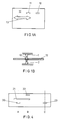
- Fig. 1A schematically shows a movable body 12, comprising one or more openings 10, 11.
- body 12 is plate-shaped and the body is capable of moving along a predetermined path in the direction indicated by an arrow 13.
- Fig. 1 B shows a portion of body 12 in cross section at opening 10.
- a transmitter 1 radiating light during operation
- a light-sensitive receiver 2 Arranged on opposite sides of the body, along the path of openings 10, 11, are a transmitter 1, radiating light during operation, and a light-sensitive receiver 2.
- the light need not be visible; in principle, infrared or ultraviolet light can also be used.
- Transmitter 1 can, for instance, be a light-emitting diode (LED) and the light-sensitive receiver can, for instance, be a phototransistor.
- the receiver does not receive any light originating from the transmitter. However, as soon as an opening of body 12 is located between the transmitter and the receiver, the receiver receives the light emitted by the transmitter. Subsequently, the transmitter provides a corresponding output signal, which may serve to energize a control device of the sliding roof and/or a reproducing device.
- Fig. 2A shows a variant, body 12 being coupled to a toothed wheel assembly 14, 15.
- the coupling comprises a toothed rack 16.
- Fig. 2B again shows transmitter 1 and receiver 2, mounted on opposite sides of toothed wheel 15 along the path of openings 10, 11.
- the transmitter and the receiver are capable of communicating with each other as soon as an opening 10, 11 is located precisely between the transmitter and the receiver and in linewith the transmitter and the receiver. Because the location of the openings is known, the position of toothed wheel 15 and hence the position of the sliding roof, fixedly coupled thereto, are also known, as soon as the receiver receives light from the transmitter.
- the output signal of the receiver may again serve to control a driving device of the sliding roof.
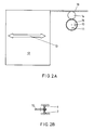
- the light emitted by transmitter 1 and shining through a small hole 5 in a movable body 4 is received by a light guide 3 and deflected to a photoreceiver 2, disposed on the same carrier 6 as transmitter 1.
- Receiver 2 receives the light signal and transmits it to control apparatus 7 so as to control the sliding roof or a similar movable body, for instance via a motor.
- receiver can be positioned in any desired plane and need not be positioned directly opposite the transmitter, as in the case of the traditional detecting/positioning devices.
- the transmitter and the receiver can advantageously be positioned in the same plane.
- an important advantage of this construction is that if more than one transmitter is used, together with several small holes and/or slots located side by side in bands so as to make a multibit code possible, only one receiver is required. The point is that, by activating the transmitters in turns and simultaneously considering the output of the photoreceiver, it can be determined which transmitter transmitted the light signal received at a given moment. This principle is known as multiplexing. Thus, a significantsav- ing of cost can be realized. It is also possible to use, for instance, one transmitter and several receivers. The code can then be derived directly from the receiver.
- the position of a movable body can be determined at any time.
- the device according to the invention can be connected to the control which controls the motor that causes the roof to move.
- the control receives a signal and can determine the instantaneous position of the roof and 'act' accordingly.
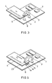
- Figs 4 and 5 show a diagram focussed on a specific exemplary embodiment, viz. a sliding roof construction of an automobile.
- the sliding roof in the example has three positions to be detected:
- Fig. 5 shows a flat plate connected to the sliding roof, provided with openings 20-23, indicating the position.
- Transmitters 1a, 1b and 1c are disposed on a printed circuit board 6, as is photoreceiver 2.
- Transmitter 1a can shine through opening 23; the light of transmitters 1 b and 1 c is blocked by plate 4.
- the position is now: horizontally open.
- the light of transmitter 1a is guided to photoreceiver 2 via light guide 3.
- transmitters 1b and 1c are located opposite openings 21 and 22.
- the receiver then receives light from both transmitters. This can for instance take place in time shift (multiplex system).
- the long slot 21 and opening 20 are located simultaneously opposite transmitters 1a and 1b, which can also be detected again.
- transmitters can be used which emit light at wavelengths specifically belonging to a particular transmitter. At the receiver end it can then be determined, on the basis of the spectrum of the light received, from which transmitters the light has originated. This does not require time multiplexing, but it does require suitable receivers and/orfrequency filters.
- the use of several openings and corresponding transmitters makes it possible to code and detect, by relatively simple means, a great number of positions of plate 4 and hence of a body connected thereto, such as a sliding roof.
- a similar effect can be obtained with a single transmitter and several receivers or with a plurality of transmitters and a plurality of receivers.
- the light guide or light guides can be located either at the transmitter end or at the receiver end.
- Suitable light guides can be constructed in various manners, for instance by means of prisms and/or suitably ground glass elements, optionally provided with internally reflecting spots. Also, optical fibres, lenses and the like can be part of the light guide.
- the light guide may have one end mechanically fixed relative to the transmitter or receiver, the other end being provided with positioning means for the receiver or transmitter, respectively.
Landscapes
- Physics & Mathematics (AREA)
- Life Sciences & Earth Sciences (AREA)
- General Life Sciences & Earth Sciences (AREA)
- General Physics & Mathematics (AREA)
- Geophysics (AREA)
- Engineering & Computer Science (AREA)
- Mechanical Engineering (AREA)
- Length Measuring Devices By Optical Means (AREA)
- Optical Transform (AREA)
- Power-Operated Mechanisms For Wings (AREA)
- Optical Radar Systems And Details Thereof (AREA)
Applications Claiming Priority (2)
| Application Number | Priority Date | Filing Date | Title |
|---|---|---|---|
| NL9200449A NL9200449A (nl) | 1992-03-11 | 1992-03-11 | Inrichting voor detectie van de positie van een beweegbaar lichaam. |
| NL9200449 | 1992-03-11 |
Publications (2)
| Publication Number | Publication Date |
|---|---|
| EP0560459A1 true EP0560459A1 (de) | 1993-09-15 |
| EP0560459B1 EP0560459B1 (de) | 1998-12-30 |
Family
ID=19860543
Family Applications (1)
| Application Number | Title | Priority Date | Filing Date |
|---|---|---|---|
| EP19930200717 Expired - Lifetime EP0560459B1 (de) | 1992-03-11 | 1993-03-11 | Anordnung zur Feststellung der Lage eines beweglichen Körpers |
Country Status (3)
| Country | Link |
|---|---|
| EP (1) | EP0560459B1 (de) |
| DE (1) | DE69322802T2 (de) |
| NL (1) | NL9200449A (de) |
Cited By (4)
| Publication number | Priority date | Publication date | Assignee | Title |
|---|---|---|---|---|
| GB2438422A (en) * | 2006-05-22 | 2007-11-28 | Memco Ltd | Obstacle detecting apparatus for a powered door system |
| GB2454025A (en) * | 2007-10-26 | 2009-04-29 | Primax Electronics Ltd | Motor driving system |
| CN101436845B (zh) * | 2007-11-12 | 2010-07-14 | 致伸科技股份有限公司 | 电动打孔机的马达驱动系统 |
| US11187022B1 (en) | 2001-07-13 | 2021-11-30 | Steven M. Hoffberg | Intelligent door restraint |
Citations (7)
| Publication number | Priority date | Publication date | Assignee | Title |
|---|---|---|---|---|
| FR2442457A1 (fr) * | 1978-11-27 | 1980-06-20 | Optel | Dispositif photoelectrique a double faisceau et systeme reflechissant selectif |
| EP0072386A1 (de) * | 1981-08-19 | 1983-02-23 | MANNESMANN Aktiengesellschaft | Impulsgeber zum Erzeugen von elektronischen Impulsfolgen |
| EP0230517A2 (de) * | 1986-01-20 | 1987-08-05 | AG für industrielle Elektronik AGIE Losone bei Locarno | Lichtschranke |
| EP0283760A1 (de) * | 1987-03-03 | 1988-09-28 | Eta SA Fabriques d'Ebauches | Vorrichtung zur Feststellung des Durchgangs eines bewegenden Organs durch eine Referenzposition |
| DE3716389A1 (de) * | 1987-05-15 | 1988-11-24 | Bayerische Motoren Werke Ag | Pruefvorrichtung fuer gelochte blechteile |
| US4893120A (en) * | 1986-11-26 | 1990-01-09 | Digital Electronics Corporation | Touch panel using modulated light |
| EP0443216A1 (de) * | 1990-02-23 | 1991-08-28 | Vermeulen-Hollandia Octrooien Ii B.V. | Aufbau eines elektrischen Schiebedaches |
-
1992
- 1992-03-11 NL NL9200449A patent/NL9200449A/nl not_active Application Discontinuation
-
1993
- 1993-03-11 EP EP19930200717 patent/EP0560459B1/de not_active Expired - Lifetime
- 1993-03-11 DE DE1993622802 patent/DE69322802T2/de not_active Expired - Fee Related
Patent Citations (7)
| Publication number | Priority date | Publication date | Assignee | Title |
|---|---|---|---|---|
| FR2442457A1 (fr) * | 1978-11-27 | 1980-06-20 | Optel | Dispositif photoelectrique a double faisceau et systeme reflechissant selectif |
| EP0072386A1 (de) * | 1981-08-19 | 1983-02-23 | MANNESMANN Aktiengesellschaft | Impulsgeber zum Erzeugen von elektronischen Impulsfolgen |
| EP0230517A2 (de) * | 1986-01-20 | 1987-08-05 | AG für industrielle Elektronik AGIE Losone bei Locarno | Lichtschranke |
| US4893120A (en) * | 1986-11-26 | 1990-01-09 | Digital Electronics Corporation | Touch panel using modulated light |
| EP0283760A1 (de) * | 1987-03-03 | 1988-09-28 | Eta SA Fabriques d'Ebauches | Vorrichtung zur Feststellung des Durchgangs eines bewegenden Organs durch eine Referenzposition |
| DE3716389A1 (de) * | 1987-05-15 | 1988-11-24 | Bayerische Motoren Werke Ag | Pruefvorrichtung fuer gelochte blechteile |
| EP0443216A1 (de) * | 1990-02-23 | 1991-08-28 | Vermeulen-Hollandia Octrooien Ii B.V. | Aufbau eines elektrischen Schiebedaches |
Non-Patent Citations (1)
| Title |
|---|
| PATENT ABSTRACTS OF JAPAN vol. 6, no. 59 (P-110)16 April 1982 & JP-A-57 000 573 ( MATSUSHITA ELECTRIC IND CO ) 5 January 1982 * |
Cited By (6)
| Publication number | Priority date | Publication date | Assignee | Title |
|---|---|---|---|---|
| US11187022B1 (en) | 2001-07-13 | 2021-11-30 | Steven M. Hoffberg | Intelligent door restraint |
| GB2438422A (en) * | 2006-05-22 | 2007-11-28 | Memco Ltd | Obstacle detecting apparatus for a powered door system |
| GB2438422B (en) * | 2006-05-22 | 2009-09-23 | Memco Ltd | Obstacle-detecting apparatus for a powered door system |
| GB2454025A (en) * | 2007-10-26 | 2009-04-29 | Primax Electronics Ltd | Motor driving system |
| GB2454025B (en) * | 2007-10-26 | 2012-03-07 | Primax Electronics Ltd | Motor driving system |
| CN101436845B (zh) * | 2007-11-12 | 2010-07-14 | 致伸科技股份有限公司 | 电动打孔机的马达驱动系统 |
Also Published As
| Publication number | Publication date |
|---|---|
| DE69322802D1 (de) | 1999-02-11 |
| NL9200449A (nl) | 1993-10-01 |
| EP0560459B1 (de) | 1998-12-30 |
| DE69322802T2 (de) | 1999-09-09 |
Similar Documents
| Publication | Publication Date | Title |
|---|---|---|
| US6376824B1 (en) | Optical sensor | |
| EP1043780A4 (de) | Vorrichtung mit optischem kommunikationsmittel | |
| JP2000097727A (ja) | 直線運動又は回転運動の定量検出用光学装置 | |
| US5560245A (en) | Moisture activated wiper sensor | |
| EP0817280A3 (de) | Optischer Sensor zum Lesen von einem Muster | |
| JPH0131132B2 (de) | ||
| CN106464251B (zh) | 用于光电式检测选挡杆位置的设备和方法、选挡杆设备及其制造方法 | |
| US4160522A (en) | Automatic car identification system | |
| EP0560459A1 (de) | Anordnung zur Feststellung der Lage eines beweglichen Körpers | |
| KR101046247B1 (ko) | 지폐 판별 장치용 지폐 탐지 유닛 | |
| GB2208433A (en) | Detecting water droplets on a vehicle window and controlling windscreen wiper in response thereto | |
| SG187257A1 (en) | Device for detecting, monitoring and/or controlling racing vehicles | |
| US20110067515A1 (en) | Operating device having a bundle of light guides | |
| US6989526B2 (en) | Device for the optoelectronic detection of switching positions of a switching element | |
| US6800839B2 (en) | Device for the optoelectronic detection of switching positions of a switching element | |
| CA2062550C (en) | Optical distance measuring apparatus | |
| US6696987B1 (en) | Electronic device with illuminated operator button, the activation of said operator buttons being determined by detection of the change in the luminous reflectance | |
| US6297896B1 (en) | Optical switch and optical communication system using the same | |
| US6710322B1 (en) | Device for detecting the position of a selector lever | |
| MY129338A (en) | Optical disc apparatus | |
| US4958067A (en) | Method and apparatus for optically detecting the location of a control object in a control panel recess | |
| JPH11142186A (ja) | 光学式増分発信器 | |
| US7242017B2 (en) | Device to detect and/or characterize individual moving objects having very small dimensions | |
| JPS62100744A (ja) | カメラのレンズ情報伝達方式 | |
| JP6414508B2 (ja) | 車載機 |
Legal Events
| Date | Code | Title | Description |
|---|---|---|---|
| PUAI | Public reference made under article 153(3) epc to a published international application that has entered the european phase |
Free format text: ORIGINAL CODE: 0009012 |
|
| AK | Designated contracting states |
Kind code of ref document: A1 Designated state(s): BE DE FR GB IT NL SE |
|
| 17P | Request for examination filed |
Effective date: 19940210 |
|
| 17Q | First examination report despatched |
Effective date: 19950818 |
|
| GRAG | Despatch of communication of intention to grant |
Free format text: ORIGINAL CODE: EPIDOS AGRA |
|
| GRAG | Despatch of communication of intention to grant |
Free format text: ORIGINAL CODE: EPIDOS AGRA |
|
| GRAG | Despatch of communication of intention to grant |
Free format text: ORIGINAL CODE: EPIDOS AGRA |
|
| GRAH | Despatch of communication of intention to grant a patent |
Free format text: ORIGINAL CODE: EPIDOS IGRA |
|
| GRAH | Despatch of communication of intention to grant a patent |
Free format text: ORIGINAL CODE: EPIDOS IGRA |
|
| GRAA | (expected) grant |
Free format text: ORIGINAL CODE: 0009210 |
|
| AK | Designated contracting states |
Kind code of ref document: B1 Designated state(s): BE DE FR GB IT NL SE |
|
| REF | Corresponds to: |
Ref document number: 69322802 Country of ref document: DE Date of ref document: 19990211 |
|
| ITF | It: translation for a ep patent filed |
Owner name: MITTLER & C. S.R.L. |
|
| ET | Fr: translation filed | ||
| PLBE | No opposition filed within time limit |
Free format text: ORIGINAL CODE: 0009261 |
|
| STAA | Information on the status of an ep patent application or granted ep patent |
Free format text: STATUS: NO OPPOSITION FILED WITHIN TIME LIMIT |
|
| 26N | No opposition filed | ||
| REG | Reference to a national code |
Ref country code: GB Ref legal event code: IF02 |
|
| PG25 | Lapsed in a contracting state [announced via postgrant information from national office to epo] |
Ref country code: IT Free format text: LAPSE BECAUSE OF NON-PAYMENT OF DUE FEES Effective date: 20050311 |
|
| PGRI | Patent reinstated in contracting state [announced from national office to epo] |
Ref country code: IT Effective date: 20080301 |
|
| PGFP | Annual fee paid to national office [announced via postgrant information from national office to epo] |
Ref country code: DE Payment date: 20080528 Year of fee payment: 16 |
|
| PGFP | Annual fee paid to national office [announced via postgrant information from national office to epo] |
Ref country code: NL Payment date: 20090320 Year of fee payment: 17 |
|
| PGFP | Annual fee paid to national office [announced via postgrant information from national office to epo] |
Ref country code: GB Payment date: 20090311 Year of fee payment: 17 |
|
| PGFP | Annual fee paid to national office [announced via postgrant information from national office to epo] |
Ref country code: SE Payment date: 20090309 Year of fee payment: 17 Ref country code: IT Payment date: 20090326 Year of fee payment: 17 |
|
| PGFP | Annual fee paid to national office [announced via postgrant information from national office to epo] |
Ref country code: BE Payment date: 20090427 Year of fee payment: 17 |
|
| PGFP | Annual fee paid to national office [announced via postgrant information from national office to epo] |
Ref country code: FR Payment date: 20090311 Year of fee payment: 17 |
|
| PG25 | Lapsed in a contracting state [announced via postgrant information from national office to epo] |
Ref country code: DE Free format text: LAPSE BECAUSE OF NON-PAYMENT OF DUE FEES Effective date: 20091001 |
|
| BERE | Be: lapsed |
Owner name: NEDERLANDSCHE APPARATENFABRIEK *NEDAP N.V. Effective date: 20100331 |
|
| REG | Reference to a national code |
Ref country code: NL Ref legal event code: V1 Effective date: 20101001 |
|
| EUG | Se: european patent has lapsed | ||
| GBPC | Gb: european patent ceased through non-payment of renewal fee |
Effective date: 20100311 |
|
| REG | Reference to a national code |
Ref country code: FR Ref legal event code: ST Effective date: 20101130 |
|
| PG25 | Lapsed in a contracting state [announced via postgrant information from national office to epo] |
Ref country code: NL Free format text: LAPSE BECAUSE OF NON-PAYMENT OF DUE FEES Effective date: 20101001 Ref country code: FR Free format text: LAPSE BECAUSE OF NON-PAYMENT OF DUE FEES Effective date: 20100331 |
|
| PG25 | Lapsed in a contracting state [announced via postgrant information from national office to epo] |
Ref country code: BE Free format text: LAPSE BECAUSE OF NON-PAYMENT OF DUE FEES Effective date: 20100331 |
|
| PG25 | Lapsed in a contracting state [announced via postgrant information from national office to epo] |
Ref country code: IT Free format text: LAPSE BECAUSE OF NON-PAYMENT OF DUE FEES Effective date: 20100311 Ref country code: GB Free format text: LAPSE BECAUSE OF NON-PAYMENT OF DUE FEES Effective date: 20100311 |
|
| PG25 | Lapsed in a contracting state [announced via postgrant information from national office to epo] |
Ref country code: SE Free format text: LAPSE BECAUSE OF NON-PAYMENT OF DUE FEES Effective date: 20100312 |