EP0560261B1 - Device for fastening of circuit boards inside a casing - Google Patents
Device for fastening of circuit boards inside a casing Download PDFInfo
- Publication number
- EP0560261B1 EP0560261B1 EP93103690A EP93103690A EP0560261B1 EP 0560261 B1 EP0560261 B1 EP 0560261B1 EP 93103690 A EP93103690 A EP 93103690A EP 93103690 A EP93103690 A EP 93103690A EP 0560261 B1 EP0560261 B1 EP 0560261B1
- Authority
- EP
- European Patent Office
- Prior art keywords
- housing
- spring
- bracket
- flanges
- circuit boards
- Prior art date
- Legal status (The legal status is an assumption and is not a legal conclusion. Google has not performed a legal analysis and makes no representation as to the accuracy of the status listed.)
- Expired - Lifetime
Links
Images

Classifications
-
- H—ELECTRICITY
- H05—ELECTRIC TECHNIQUES NOT OTHERWISE PROVIDED FOR
- H05K—PRINTED CIRCUITS; CASINGS OR CONSTRUCTIONAL DETAILS OF ELECTRIC APPARATUS; MANUFACTURE OF ASSEMBLAGES OF ELECTRICAL COMPONENTS
- H05K7/00—Constructional details common to different types of electric apparatus
- H05K7/14—Mounting supporting structure in casing or on frame or rack
- H05K7/1401—Mounting supporting structure in casing or on frame or rack comprising clamping or extracting means
- H05K7/1402—Mounting supporting structure in casing or on frame or rack comprising clamping or extracting means for securing or extracting printed circuit boards
- H05K7/1408—Mounting supporting structure in casing or on frame or rack comprising clamping or extracting means for securing or extracting printed circuit boards by a unique member which latches several boards, e.g. locking bars
Definitions
- the invention relates to a device for fixing a plurality of circuit boards in a device housing, the circuit boards each being connected at one of their edges to a strip-shaped metal diaphragm directed perpendicular to the plane of the board, each of which has a right-angled flange at one of its longitudinal ends, and wherein the circuit boards can be inserted into the housing parallel to one another in such a way that the metal covers on the one hand and their flanges on the other are each in one plane.
- the electronic circuit boards or plug-in cards are connected to the edge cards Central processor (CPU) connected.
- CPU Central processor
- the interfaces (usually D-sub sockets) to the respective plug connection to the plug-in card are located on one of the above-mentioned metal panels, which in turn is connected to the device housing with a screw in a metallically conductive manner.
- the invention has for its object to provide an easy and safe to use device of the type mentioned, with which the plug-in cards and panels can be reliably fixed while ensuring electrical contact between the metal panels and the housing.
- a metal retaining bracket which extends between the housing walls directed parallel to the circuit boards perpendicular to the latter and extends over the flanges of the metal panels, can be connected to the housing in a positive and / or non-positive manner and is intended for bearing against the individual flanges Has spring elements.
- the retaining bracket is formed by a U-shaped rail made of spring steel, from whose U-transverse web intended for abutment on the flanges, spring tongues are punched out, which are bent obliquely outward from the plane of the U-transverse web in the open state of the retaining bracket.
- the spring elements are pressed back into the plane of the U-crossbar, scraping along the surface of the flanges and thereby creating reliable electrical contact between the bracket and the metal covers.
- the bracket By simply pulling the handle section of the spring clip, the bracket can be released again.
- the spring tongues are preferably punched out in such a way that their free ends point away from the longitudinal end of the holding bracket provided with the tongue. This causes the spring tongues to scrape along the flanges of the metal panels when the holding bracket is pivoted and to dig into the material.
- the holding bracket 10 shown in FIGS. 1 and 2 essentially consists of a U-shaped rail 12 made of spring steel with U-legs 14 and a U-cross bar 16. At one longitudinal end, the U-cross bar 16 has a tongue 18 formed integrally with it At its opposite end, an extension section of the U-cross bar 16 is bent into a spring clip 20. This includes a first spring leg 22, which is bent perpendicularly from the U-crosspiece 16 to the opposite side to the direction of extension of the U-leg 14, and a U-shaped bent back, compared to the spring leg 22 longer second spring leg 24, one at its free end has angled handle portion 26.
- Pairs of spring tongues 28 are punched out of the U-cross bar 16 and are angled outward from the plane of the U-cross leg 16, as can be seen in FIG. 2.
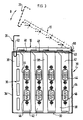
- FIG. 3 schematically shows a device housing 30 for receiving electronic circuit boards (not shown).
- the housing 30 comprises a base 32, side walls 34 and a grid-shaped rear wall 36, which in the present example is connected to the base 32 and comprises a number of struts 38 which are oriented parallel to the side walls 34 and which on their side Bottom 32 far end are interconnected by a web 40 bent outward at right angles.
- the circuit boards, not shown, are inserted into this housing in such a way that they are directed parallel to the side walls 34.
- a metal screen 42 is connected to each of the circuit boards via edge connectors, the surface of which is directed perpendicular to the plane of the respective circuit board.
- the metal panels 42 each carry plugs 44, 46 for connecting the circuit boards to other parts of the device or external devices.
- the arrangement of the circuit boards in the device housing 30 is such that the panels 42 with their plugs 44, 46 lie in the gaps between two struts 38 of the rear wall 36.
- the panels 42 each have a right-angled flange 48 which rests on the web 40 of the rear wall 36 when the plug-in card is fully inserted. So far, this flange 48 has been screwed to the web 40.
- the metal screens 42 and thus also the plug-in cards are fixed in the housing 30 with the aid of the holding bracket 10 described with reference to FIGS. 1 and 2. This is shown in FIG. 3 by solid lines in its closed position and by Dashed lines shown in an open position.
- the retaining bracket is inserted with the tongue 18 into a slot 50 of the right side wall 34 in FIG.
- bracket 10 can then be pivoted in the direction of the double arrow B in FIG. 3.
- this is pressed down against the flanges 48 of the metal panels 42, the spring tongues 28 being pressed back into the plane of the U-crosspiece 16 of the bracket 10 and thereby dig into the material of the flanges 48.
- the securing bracket 10 in the closed position shown by solid lines is done by inserting the spring clip 20 into a recess 52 in the web 40 of the housing rear wall 36. The spring legs of the spring clip 20 are compressed so that they are under pressure at the edges of the recess 52 rest and thus secure the bracket 10 in the closed position.
- the holding bracket 10 By simply pulling on the grip section 26, the holding bracket 10 can be pivoted away from the flanges 48 and the connection of the metal screens 42 to the housing 30 can thus be released. In this way, the replacement of plug-in cards can be done quickly and easily, without the risk that fasteners can fall into the device.
Description
Die Erfindung betrifft eine Vorrichtung zum Festlegen einer Mehrzahl von Schaltungsplatinen in einem Gerätegehäuse, wobei die Schaltungsplatinen jeweils an einem ihrer Ränder mit einer senkrecht zur Platinenebene gerichteten streifenförmigen Metallblende verbunden sind, die jeweils an einem ihrer Längsenden einen rechtwinklig abgebogenen Flansch hat, und wobei die Schaltungsplatinen parallel zueinander so in das Gehäuse einsteckbar sind, daß die Metallblenden einerseits und ihre Flansche andererseits jeweils in einer Ebene liegen.The invention relates to a device for fixing a plurality of circuit boards in a device housing, the circuit boards each being connected at one of their edges to a strip-shaped metal diaphragm directed perpendicular to the plane of the board, each of which has a right-angled flange at one of its longitudinal ends, and wherein the circuit boards can be inserted into the housing parallel to one another in such a way that the metal covers on the one hand and their flanges on the other are each in one plane.
In allen bekannten PC's (Personal Computers) und PC-ähnlichen Geräten werden die elektronischen Schaltungsplatinen oder Steckkarten über Randkarten mit dem Zentralprozessor (CPU) verbunden. Die Schnittstellen (in der Regel D-sub-Steckdosen) zum jeweiligen Steckeranschluß an die Steckkarte befinden sich auf einer der oben genannten Metallblenden, die wiederum im Gerät mit einer Schraube metallisch leitend mit dem Gerätegehäuse verbunden wird.In all known PC's (personal computers) and PC-like devices, the electronic circuit boards or plug-in cards are connected to the edge cards Central processor (CPU) connected. The interfaces (usually D-sub sockets) to the respective plug connection to the plug-in card are located on one of the above-mentioned metal panels, which in turn is connected to the device housing with a screw in a metallically conductive manner.
Bei der vorstehend beschriebenen herkömmlichen Lösung müssen beim Einsetzen und Wechseln der elektronischen Steckkarten jeweils eine oder mehrere Schrauben eingeschraubt oder gelöst werden. Neben dem damit verbundenen Aufwand hat dies den weiteren Nachteil, daß immer wieder Schrauben in das Gerät fallen. Diese können zu Kurzschlüssen und damit zu Schäden am Gerät führen. Zumindest ist jedoch häufig ein erheblicher Aufwand notwendig, um die Schrauben wieder zu entfernen.In the conventional solution described above, one or more screws have to be screwed in or loosened when inserting and changing the electronic plug-in cards. In addition to the effort involved, this has the further disadvantage that screws repeatedly fall into the device. These can lead to short circuits and thus damage to the device. At least, however, considerable effort is often required to remove the screws again.
Der Erfindung liegt die Aufgabe zugrunde, eine leicht und sicher zu handhabende Vorrichtung der eingangs genannten Art anzugeben, mit der die Steckkarten und Blenden zuverlässig festgelegt werden können unter gleichzeitiger Gewährleistung eines elektrischen Kontaktes zwischen den Metallblenden und dem Gehäuse.The invention has for its object to provide an easy and safe to use device of the type mentioned, with which the plug-in cards and panels can be reliably fixed while ensuring electrical contact between the metal panels and the housing.
Diese Aufgabe wird erfindungsgemäß durch einen metallischen Haltebügel gelöst, der sich zwischen den parallel zu den Platinen gerichteten Gehäusewänden senkrecht zu diesen der über die Flansche der Metallblenden erstreckt, mit dem Gehäuse form- und/oder kraftschlüssig verbindbar ist und zur Anlage an den einzelnen Flanschen bestimmte Federelemente hat.This object is achieved according to the invention by means of a metal retaining bracket which extends between the housing walls directed parallel to the circuit boards perpendicular to the latter and extends over the flanges of the metal panels, can be connected to the housing in a positive and / or non-positive manner and is intended for bearing against the individual flanges Has spring elements.
Mit diesem Haltebügel können sämtliche Steckkarten in einem einzigen Arbeitsgang freigegeben oder festgelegt werden. Das Lösen oder Einsetzen von Schrauben an den einzelnen Blenden ist nicht erforderlich. Die Federelemente an dem Haltebügel gewährleisten einen guten elektrischen Kontakt zwischen den einzelnen Metallblenden und dem Gehäuse.With this bracket, all plug-in cards can be released or fixed in a single operation. Loosening or inserting screws on the individual panels are not required. The spring elements on the bracket ensure good electrical contact between the individual metal panels and the housing.
Vorzugsweise ist der Haltebügel von einer U-Profilschiene aus Federstahl gebildet, aus deren zur Anlage an den Flanschen bestimmten U-Quersteg Federzungen ausgestanzt sind, die im offenen Zustand des Haltebügels aus der Ebene des U-Quersteges schräg nach außen gebogen sind. Damit vereinfacht sich die Herstellung des Haltebügels. Beim Schließen des Haltebügels werden die Federelemente in die Ebene des U-Quersteges zurückgedrückt, wobei sie auf der Oberfläche der Flansche entlangkratzen und dabei einen zuverlässigen elektrischen Kontakt zwischen dem Haltebügel und den Metallblenden schaffen.Preferably, the retaining bracket is formed by a U-shaped rail made of spring steel, from whose U-transverse web intended for abutment on the flanges, spring tongues are punched out, which are bent obliquely outward from the plane of the U-transverse web in the open state of the retaining bracket. This simplifies the manufacture of the bracket. When the bracket is closed, the spring elements are pressed back into the plane of the U-crossbar, scraping along the surface of the flanges and thereby creating reliable electrical contact between the bracket and the metal covers.
Zur Verbindung des Haltebügels mit dem Gehäuse wird erfindungsgemäß vorgeschlagen, daß der Haltebügel an seinem einen Längsende eine Zunge zum Einstecken in einen Schlitz in einer der Gehäusewände und an seinem anderen Längsende eine Federklammer trägt, die zum Eingriff mit einer Gehäusekante bestimmt ist. Damit kann der Haltebügel an dem Gehäuse festgelegt werden, ohne daß hierzu separate Befestigungselemente erforderlich wären.To connect the retaining bracket to the housing, it is proposed according to the invention that the retaining bracket carries a tongue at one longitudinal end for insertion into a slot in one of the housing walls and a spring clip at its other longitudinal end which is intended for engagement with a housing edge. This allows the bracket to be fixed to the housing without the need for separate fasteners.
Vorzugsweise ist die Federklammer aus einem Verlängerungsabschnitt des U-Quersteges gebogen mit einem ersten Schenkel, der senkrecht zum U-Quersteg nach der Seite hin gerichtet ist, nach der auch die Federzungen weisen, und mit einem U-förmig zurückgebogenen zweiten Schenkel, der länger als der erste Schenkel ist und an seinem freien Ende einen abgewinkelten Griffabschnitt hat, wobei in einer zu den Flanschen der Metallblende parallelen gehäusefesten Fläche eine Aussparung vorgesehen ist, in welche die Federklammer unter Zusammendrücken der beiden Schenkel einsteckbar ist. Beim Einsetzen und Festlegen des Haltebügels wird dieser also mit der Zunge in den Schlitz in der Gehäusewand eingesteckt, um diese Zunge herum verschwenkt, bis die U-Profilschiene auf den Flanschen der Metallblenden aufliegt, wobei die Federklammer in die Aussparung der gehäusefesten Fläche eingedrückt wird. Durch einfaches Ziehen an dem Griffabschnitt der Federklammer kann der Haltebügel wieder gelöst werden. Vorzugsweise sind bei dieser Anordnung die Federzungen derart ausgestanzt, daß sie mit ihren freien Enden von dem mit der Zunge versehenen Längsende des Haltebügels wegweisen. Dies bewirkt, daß die Federzungen beim Verschwenken des Haltebügels auf den Flanschen der Metallblenden entlang schaben und sich in das Material eingraben.Preferably, the spring clip is bent from an extension section of the U-cross bar with a first leg, which is directed perpendicular to the U-cross bar to the side to which the spring tongues also point, and with a U-shaped bent back leg, which is longer than the first leg is and at its free end an angled handle portion has, in which a recess is provided in a parallel to the flanges of the metal panel fixed surface into which the spring clip can be inserted by pressing the two legs together. When inserting and fixing the bracket, it is inserted with the tongue into the slot in the housing wall, pivoted around this tongue, until the U-shaped rail rests on the flanges of the metal panels, the spring clip being pressed into the recess in the surface fixed to the housing. By simply pulling the handle section of the spring clip, the bracket can be released again. In this arrangement, the spring tongues are preferably punched out in such a way that their free ends point away from the longitudinal end of the holding bracket provided with the tongue. This causes the spring tongues to scrape along the flanges of the metal panels when the holding bracket is pivoted and to dig into the material.
Die vorstehende Beschreibung zeigt, daß mit einem einzigen Griff die elektrische und mechanische Verbindung aller Blenden mit dem Gehäuse hergestellt oder gelöst werden kann. Gleichzeitig ist die Gefahr ausgeschlossen, daß einzelne Befestigungselemente in das Gerät fallen und zu den oben beschriebenen Schäden führen können.The above description shows that the electrical and mechanical connection of all panels to the housing can be made or released with a single handle. At the same time, there is no risk that individual fastening elements will fall into the device and lead to the damage described above.
Die folgende Beschreibung erläutert in Verbindung mit den beigefügten Zeichnungen die Erfindung anhand eines Ausführungsbeispieles. Es zeigen:
- Figur 1
- eine schematische Draufsicht auf einen erfindungsgemäßen Haltebügel,
- Figur 2
- eine Seitenansicht des Haltebügels in Richtung des Pfeiles A in Figur 1 und
- Figur 3
- eine schematische Rückansicht eines Gerätegehäuses mit eingesteckten Schaltungsplatinen und Metallblenden, wobei der Haltebügel in geschlossener und geöffneter Stellung dargestellt ist.
- Figure 1
- 1 shows a schematic top view of a holding bracket according to the invention
- Figure 2
- a side view of the bracket in the direction of arrow A in Figure 1 and
- Figure 3
- is a schematic rear view of a device housing with inserted circuit boards and metal panels, wherein the bracket is shown in the closed and open position.
Der in den Figuren 1 und 2 dargestellte Haltebügel 10 besteht im wesentlichen aus einer U-Profilschiene 12 aus Federstahl mit U-Schenkeln 14 und einem U-Quersteg 16. An seinem einen Längsende hat der U-Quersteg 16 eine einstückig mit ihm ausgebildete Zunge 18. An seinem entgegengesetzten Ende ist ein Verlängerungsabschnitt des U-Quersteges 16 zu einer Federklammer 20 gebogen. Diese umfaßt einen ersten Federschenkel 22, der von U-Quersteg 16 senkrecht nach der zur Erstreckungsrichtung der U-Schenkel 14 entgegengesetzten Seite umgebogen ist, und einen U-förmig zurückgebogenen, gegenüber dem Federschenkel 22 längeren zweiten Federschenkel 24, der an seinem freien Ende einen abgewinkelten Griffabschnitt 26 hat.The
Aus dem U-Quersteg 16 sind jeweils Paare von Federzungen 28 ausgestanzt, die aus der Ebene des U-Querschenkels 16 schräg nach außen abgewinkelt sind, wie dies in Figur 2 zu erkennen ist.Pairs of
Figur 3 zeigt in schematischer Weise ein Gerätegehäuse 30 zur Aufnahme von nicht dargestellten elektronischen Schaltungsplatinen. Das Gehäuse 30 umfaßt einen Boden 32, Seitenwände 34 und eine gitterförmige Rückwand 36, die im vorliegenden Beispiel mit dem Boden 32 zusammenhängt und eine Anzahl von parallel zu den Seitenwänden 34 gerichteten Streben 38 umfaßt, die an ihrem dem Boden 32 fernen Ende durch einen rechtwinklig nach außen umgebogenen Steg 40 miteinander verbunden sind. In dieses Gehäuse werden die nicht dargestellten Schaltungsplatinen so eingesteckt, daß sie parallel zu den Seitenwänden 34 gerichtet sind. Mit jeder der Schaltungsplatinen ist über Randstecker eine Metallblende 42 verbunden, deren Fläche senkrecht zur Ebene der jeweiligen Schaltungsplatine gerichtet ist. Die Metallblenden 42 tragen jeweils Stecker 44, 46 zur Verbindung der Schaltungsplatinen mit anderen Teilen des Gerätes oder externen Geräten.FIG. 3 schematically shows a device housing 30 for receiving electronic circuit boards (not shown). The
Die Anordnung der Schaltungsplatinen in dem Gerätegehäuse 30 ist so getroffen, daß die Blenden 42 mit ihren Steckern 44, 46 in den Lücken zwischen je zwei Streben 38 der Rückwand 36 liegen. Die Blenden 42 haben jeweils einen rechtwinklig abgebogenen Flansch 48, der bei vollständig eingesteckter Steckkarte auf dem Steg 40 der Rückwand 36 aufliegt. Bisher wurde dieser Flansch 48 jeweils mit dem Steg 40 verschraubt. Bei der in Figur 3 dargestellten Lösung jedoch erfolgt das Festlegen der Metallblenden 42 und damit auch der Steckkarten in dem Gehäuse 30 mit Hilfe des anhand der Figuren 1 und 2 beschriebenen Haltebügels 10. Dieser ist in Figur 3 durch ausgezogene Linien in seiner geschlossenen Stellung und durch gestrichelte Linien in einer geöffneten Stellung dargestellt. Der Haltebügel wird mit der Zunge 18 in einen Schlitz 50 der in der Figur 3 rechten Seitenwand 34 eingesteckt und kann dann in Richtung des Doppelpfeiles B in Figur 3 verschwenkt werden. Zum Schließen des Haltebügels 10 wird dieser nach unten gegen die Flansche 48 der Metallblenden 42 gedrückt, wobei die Federzungen 28 in die Ebene des U-Quersteges 16 des Haltebügels 10 zurückgedrückt werden und dabei sich in das Material der Flansche 48 eingraben. Die Sicherung des Haltebügels 10 in der durch ausgezogene Linien wiedergegebenen Schließstellung erfolgt durch das Einstecken der Federklammer 20 in eine Aussparung 52 in dem Steg 40 der Gehäuserückwand 36. Dabei werden die Federschenkel der Federklammer 20 zusammengedrückt, so daß sie unter Druck an den Rändern der Aussparung 52 anliegen und damit den Haltebügel 10 in der Schließstellung sichern. Durch einfaches Ziehen an dem Griffabschnitt 26 kann der Haltebügel 10 von den Flanschen 48 weggeschwenkt und damit die Verbindung der Metallblenden 42 mit dem Gehäuse 30 gelöst werden. Auf diese Weise kann das Auswechseln von Steckkarten rasch und bequem erfolgen, ohne daß die Gefahr besteht, daß Befestigungselemente in das Gerät fallen können.The arrangement of the circuit boards in the
Claims (5)
- Device for fixing a plurality of circuit boards in an apparatus housing (30), the circuit boards each being connected on one of their edges to a metal panel (42) which is in the form of a strip, is directed at right angles to the board plane and has on one of its longitudinal ends a flange (48) which is bent out at right angles, it being possible to insert the circuit boards into the housing (30) parallel to one another such that the metal panels (42) on the one hand and their flanges (48) on the other hand in each case lie in a plane, characterized by a metallic retaining bracket (10) which extends between the housing walls (34), which are directed parallel to the boards, at right angles thereto and transversely over the flanges (48) of the metal panels (42), can be connected to the housing (30) in a positively locking and/or force-fitting manner, and has spring elements (28) which are intended to rest on the individual flanges (48).
- Device according to Claim 1, characterized in that the retaining bracket (10) is formed from a U-profiled rail (12) made of spring steel, out of whose U-transverse web (16), which is intended to rest on the flanges (48), spring tongues (28) are stamped which, when the retaining bracket (10) is in the open state, are bent obliquely outwards from the plane of the U-transverse web (16).
- Device according to Claim 1 or 2, characterized in that the retaining bracket (10) has on its one longitudinal end a tongue (18) for insertion into a slot (50) in one of the housing walls (34) and, on its other longitudinal end, a spring bracket (20) which is intended to engage with an edge which is fixed to the housing.
- Device according to Claim 3, characterized in that the spring tongues (28) are stamped in such a manner that their free ends point away from that longitudinal end of the retaining bracket (10) which is provided with the tongue (18).
- Device according to one of Claims 2 to 4, characterized in that the spring bracket (20) is bent out of an extension section of the U-transverse web (16), having a first limb (22) which is directed at right angles to the U-transverse web (16) towards the side towards which the spring tongues (28) also point, and having a second limb (24), which is bent back in a U-shape, is longer than the first limb (22) and has a gripping section (26), which is bent outwards, on its free end, a cutout (52) being provided on a surface (40) which is fixed to the housing and is parallel to the flanges (48) of the metal panels (42), into which cutout the spring bracket (20) can be inserted, with its two limbs (22, 24) being compressed.
Applications Claiming Priority (2)
| Application Number | Priority Date | Filing Date | Title |
|---|---|---|---|
| DE4207572 | 1992-03-10 | ||
| DE4207572A DE4207572C1 (en) | 1992-03-10 | 1992-03-10 |
Publications (2)
| Publication Number | Publication Date |
|---|---|
| EP0560261A1 EP0560261A1 (en) | 1993-09-15 |
| EP0560261B1 true EP0560261B1 (en) | 1995-05-31 |
Family
ID=6453678
Family Applications (1)
| Application Number | Title | Priority Date | Filing Date |
|---|---|---|---|
| EP93103690A Expired - Lifetime EP0560261B1 (en) | 1992-03-10 | 1993-03-08 | Device for fastening of circuit boards inside a casing |
Country Status (3)
| Country | Link |
|---|---|
| EP (1) | EP0560261B1 (en) |
| DE (2) | DE4207572C1 (en) |
| ES (1) | ES2072782T3 (en) |
Families Citing this family (5)
| Publication number | Priority date | Publication date | Assignee | Title |
|---|---|---|---|---|
| DE4403907A1 (en) * | 1994-02-08 | 1995-08-10 | Vobis Microcomputer Ag | Personal computer with a housing, a motherboard, plug-in cards and a holding device therefor |
| FR2762500B1 (en) * | 1997-04-23 | 1999-06-11 | Rodolphe Reisch | RACK FURNITURE |
| ES2169697B1 (en) * | 2000-11-03 | 2003-11-01 | Lear Automotive Eeds Spain | PERFECTED DEVICE FOR FIXING DISTRIBUTION BOXES. |
| DE10064115C1 (en) * | 2000-12-21 | 2002-06-20 | Fujitsu Siemens Computers Gmbh | Slot card fixing device for computer housing uses fixing element formed integral with cover of computer housing |
| DE10209083C2 (en) * | 2002-03-01 | 2003-12-24 | Fujitsu Siemens Computers Gmbh | Arrangement for determining a slot angle |
Family Cites Families (4)
| Publication number | Priority date | Publication date | Assignee | Title |
|---|---|---|---|---|
| DE2757761A1 (en) * | 1977-12-23 | 1979-06-28 | Siemens Ag | Rack frame for electronic component mounting - has release spring attached to frame and rear side of locking rail over edge of component unit |
| CH667959A5 (en) * | 1985-07-26 | 1988-11-15 | Contraves Ag | Housing frame for electronic rack mounted circuit boards - has hinged front carrier unit that retains modules and provides handles for carrying |
| US5067041A (en) * | 1989-10-27 | 1991-11-19 | International Business Machines Corporation | Apparatus for reducing electromagnetic radiation from a computer device |
| DE9003253U1 (en) * | 1990-03-20 | 1991-08-01 | Siemens Nixdorf Informationssysteme Ag, 4790 Paderborn, De |
-
1992
- 1992-03-10 DE DE4207572A patent/DE4207572C1/de not_active Expired - Fee Related
-
1993
- 1993-03-08 DE DE59300225T patent/DE59300225D1/en not_active Expired - Fee Related
- 1993-03-08 ES ES93103690T patent/ES2072782T3/en not_active Expired - Lifetime
- 1993-03-08 EP EP93103690A patent/EP0560261B1/en not_active Expired - Lifetime
Also Published As
| Publication number | Publication date |
|---|---|
| EP0560261A1 (en) | 1993-09-15 |
| DE59300225D1 (en) | 1995-07-06 |
| ES2072782T3 (en) | 1995-07-16 |
| DE4207572C1 (en) | 1993-07-22 |
Similar Documents
| Publication | Publication Date | Title |
|---|---|---|
| DE602005000149T2 (en) | Connection arrangement of an electrical device | |
| DE2925938A1 (en) | ELECTRIC FLAT CONNECTOR | |
| DE2409075A1 (en) | ELECTRIC CONNECTOR | |
| EP0793313A2 (en) | Right angled press fit connector to press in printed circuit holes | |
| EP2375503A2 (en) | Actuation device for an electric connection terminal | |
| EP2023440A2 (en) | Attachment device, assembly of attachment devices and method for mounting attachment devices to a component | |
| EP0735615A2 (en) | Connecting terminal for electrical devices | |
| DE102009019699A1 (en) | Electrical connection terminal i.e. spring loaded terminal, for contacting electrical conductor conducting path to printed circuit board, has contact support whose section forms linear warped contact to electrical conducting system | |
| EP0780923B1 (en) | Clamp for connecting a conductor end with a contact | |
| EP0666524A2 (en) | Personal computer with housing, mother board, plug-in cards, and related retaining device | |
| EP0822337B1 (en) | Mounting device for electric fan, particularly a miniature fan | |
| DE4000548A1 (en) | POWER STRIP | |
| EP0560261B1 (en) | Device for fastening of circuit boards inside a casing | |
| DE4433735A1 (en) | Swivel connector for planar electronic devices | |
| EP0483532B1 (en) | Terminal arrangement for printed circuit boards | |
| EP0433688A1 (en) | Contacting apparatus for an electronic card with side connecting terminals, particularly an IC-memory card, with a mother board | |
| DE102018101792B4 (en) | Circuit card connector and associated circuit card arrangement for the transmission of high currents | |
| DE7011611U (en) | FORK-SHAPED CONTACT SPRING. | |
| DE19830878B4 (en) | Electrical connection arrangement between two electrical components for an electrical component | |
| DE4016797C2 (en) | Device for high-frequency-tight shielding of a slide-in housing | |
| DE19610610A1 (en) | Arrangement for connecting electrical conductor to insulation piercing contact | |
| DE2910810C2 (en) | Contact spring | |
| DE4139550A1 (en) | Electric connector for electric plate and electric components - has deflectable contact tongues in wedge-shaped apertures which grip component contact terminals | |
| EP0793302A1 (en) | Flat contact spring with multiple blades | |
| WO2023152235A1 (en) | Plug connector with shield plate, comprising a spring contact element |
Legal Events
| Date | Code | Title | Description |
|---|---|---|---|
| PUAI | Public reference made under article 153(3) epc to a published international application that has entered the european phase |
Free format text: ORIGINAL CODE: 0009012 |
|
| AK | Designated contracting states |
Kind code of ref document: A1 Designated state(s): DE ES FR GB IT |
|
| 17P | Request for examination filed |
Effective date: 19940216 |
|
| 17Q | First examination report despatched |
Effective date: 19940926 |
|
| GRAA | (expected) grant |
Free format text: ORIGINAL CODE: 0009210 |
|
| AK | Designated contracting states |
Kind code of ref document: B1 Designated state(s): DE ES FR GB IT |
|
| REF | Corresponds to: |
Ref document number: 59300225 Country of ref document: DE Date of ref document: 19950706 |
|
| REG | Reference to a national code |
Ref country code: ES Ref legal event code: FG2A Ref document number: 2072782 Country of ref document: ES Kind code of ref document: T3 |
|
| ITF | It: translation for a ep patent filed |
Owner name: STUDIO JAUMANN |
|
| ET | Fr: translation filed | ||
| GBT | Gb: translation of ep patent filed (gb section 77(6)(a)/1977) |
Effective date: 19950814 |
|
| PGFP | Annual fee paid to national office [announced via postgrant information from national office to epo] |
Ref country code: ES Payment date: 19960311 Year of fee payment: 4 |
|
| PLBE | No opposition filed within time limit |
Free format text: ORIGINAL CODE: 0009261 |
|
| STAA | Information on the status of an ep patent application or granted ep patent |
Free format text: STATUS: NO OPPOSITION FILED WITHIN TIME LIMIT |
|
| PGFP | Annual fee paid to national office [announced via postgrant information from national office to epo] |
Ref country code: DE Payment date: 19960520 Year of fee payment: 4 |
|
| 26N | No opposition filed | ||
| PGFP | Annual fee paid to national office [announced via postgrant information from national office to epo] |
Ref country code: GB Payment date: 19970224 Year of fee payment: 5 |
|
| PG25 | Lapsed in a contracting state [announced via postgrant information from national office to epo] |
Ref country code: ES Free format text: LAPSE BECAUSE OF NON-PAYMENT OF DUE FEES Effective date: 19970310 |
|
| PGFP | Annual fee paid to national office [announced via postgrant information from national office to epo] |
Ref country code: FR Payment date: 19970321 Year of fee payment: 5 |
|
| PG25 | Lapsed in a contracting state [announced via postgrant information from national office to epo] |
Ref country code: DE Free format text: LAPSE BECAUSE OF NON-PAYMENT OF DUE FEES Effective date: 19980101 |
|
| PG25 | Lapsed in a contracting state [announced via postgrant information from national office to epo] |
Ref country code: GB Free format text: LAPSE BECAUSE OF NON-PAYMENT OF DUE FEES Effective date: 19980308 |
|
| PG25 | Lapsed in a contracting state [announced via postgrant information from national office to epo] |
Ref country code: FR Free format text: THE PATENT HAS BEEN ANNULLED BY A DECISION OF A NATIONAL AUTHORITY Effective date: 19980331 |
|
| GBPC | Gb: european patent ceased through non-payment of renewal fee |
Effective date: 19980308 |
|
| REG | Reference to a national code |
Ref country code: FR Ref legal event code: ST |
|
| REG | Reference to a national code |
Ref country code: ES Ref legal event code: FD2A Effective date: 19990201 |
|
| PG25 | Lapsed in a contracting state [announced via postgrant information from national office to epo] |
Ref country code: IT Free format text: LAPSE BECAUSE OF NON-PAYMENT OF DUE FEES;WARNING: LAPSES OF ITALIAN PATENTS WITH EFFECTIVE DATE BEFORE 2007 MAY HAVE OCCURRED AT ANY TIME BEFORE 2007. THE CORRECT EFFECTIVE DATE MAY BE DIFFERENT FROM THE ONE RECORDED. Effective date: 20050308 |