EP0559102B1 - Frequenzumsetzer - Google Patents
Frequenzumsetzer Download PDFInfo
- Publication number
- EP0559102B1 EP0559102B1 EP93103118A EP93103118A EP0559102B1 EP 0559102 B1 EP0559102 B1 EP 0559102B1 EP 93103118 A EP93103118 A EP 93103118A EP 93103118 A EP93103118 A EP 93103118A EP 0559102 B1 EP0559102 B1 EP 0559102B1
- Authority
- EP
- European Patent Office
- Prior art keywords
- frequency
- signal
- photodetector
- frequency converter
- photodetectors
- Prior art date
- Legal status (The legal status is an assumption and is not a legal conclusion. Google has not performed a legal analysis and makes no representation as to the accuracy of the status listed.)
- Expired - Lifetime
Links
Images
Classifications
-
- H—ELECTRICITY
- H04—ELECTRIC COMMUNICATION TECHNIQUE
- H04B—TRANSMISSION
- H04B10/00—Transmission systems employing electromagnetic waves other than radio-waves, e.g. infrared, visible or ultraviolet light, or employing corpuscular radiation, e.g. quantum communication
- H04B10/60—Receivers
-
- H—ELECTRICITY
- H03—ELECTRONIC CIRCUITRY
- H03D—DEMODULATION OR TRANSFERENCE OF MODULATION FROM ONE CARRIER TO ANOTHER
- H03D9/00—Demodulation or transference of modulation of modulated electromagnetic waves
- H03D9/06—Transference of modulation using distributed inductance and capacitance
- H03D9/0608—Transference of modulation using distributed inductance and capacitance by means of diodes
Definitions
- the present invention relates to a frequency converter which is suitable for converting high-frequency signals, such as micro-waves, into intermediate-frequency signals over a wide band.
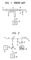
- Fig. 1 shows a conventional frequency converter.
- An input signal from an input terminal 11 is supplied via a directional coupler 12 to one end of a mixer diode 13.
- the directional coupler 12 is supplied with a local signal of a local oscillator 15 from a terminal 14 and the local signal is applied to the mixer diode 13.
- the other end of the mixer diode 13 is grounded via a capacitor 16 acting as a high-frequency signal path and, at the same time, it is connected to an output terminal 17.
- the input signal from the terminal 11 and the local signal from the terminal 14 are provided via the directional coupler 12 to the mixer diode 13, from which a component of the frequency difference between the both signals, obtained owing to the nonlinearity of the mixer diode 13, is provided as an intermediate-frequency signal to the output terminal 17.
- the input signal and the local signal are applied via the directional coupler 12 to the mixer diode 13, they are restricted by the frequency characteristics of the paths from the input terminal 11 to the junction of the mixer diode 13 and from the terminal 14 to the junction of the mixer diode 13 and it is difficult to operate the conventional frequency converter over a wide band.
- the local oscillator 15 is capable of varying a high-frequency local signal over a wide band.
- a frequency converter according to the precharacterizing clause of claim 1 is disclosed in the document US-A-4,156,135.
- this document discloses photodetector means connected to a DC voltage source via a resistor and a selected one of multiple oscillators.
- the connecting point between the photodetector means and the resistor is connected to the input of a narrow-band amplifier.
- the photodetector means receives light from a remote light source such as emitted or reflected light from a target or moving vehicle.
- the input electrical signal supplied by the selected oscillator and the optical signal received by the photodetector means are mixed by the photodetector means to result in heterodyne frequencies which are the sum and the difference frequencies of the frequencies of the two applied signals.
- this document discloses applying both of the signals to be mixed as optical signals. In this case, a local light source is provided and driven by a selected one of multiple oscillators. No input electrical signal is applied to the photodetector means in this case.
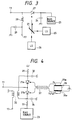
- Fig. 2 illustrates a first embodiment of the present invention.
- an input signal from the input terminal 11 is applied to one end of a photodiode 21 acting as a photodetector, the other end of which is connected to a bias power supply 23 via a high frequency blocking coil 22, grounded via a high frequency passage capacitor 24 and connected to the output terminal 17.
- An optical signal of a frequency F 0 from a light source 25 such as a laser diode and an optical signal of a frequency F 0 + ⁇ F from a light source 26 such as a laser diode are combined by light combining means 27 such as a semitransparent mirror, and the resulting interference light is applied to the photodiode 21.
- This electrical signal acts as a local signal with respect to the input signal from the input terminal 11, and owing to the nonlinearlity of the photodiode 21, an intermediate-frequency signal of a frequency
- the high-frequency component is grounded via the capacitor 24.
- the output terminal 17 may also be provided at the same side as the input terminal 11. That is, as shown in Fig. 3 wherein the parts corresponding to those in Fig. 2 are identified by the same reference numerals, the output terminal 17 is connected via a high frequency blocking coil 28 to the connection point of the input terminal 11 and the photodiode 21. If necessary, the output terminal 17 is grounded via a capacitor 29 as a high frequency path.
- Fig. 4 illustrates another embodiment of the present invention which is constructed as a balanced frequency converter.
- Photodiodes 21a and 21b are connected in series in the forward direction, one end of the series connection is grounded via a resistor 31 and grounded via capacitor 32 serving as a high frequency path, and the other end is connected via a resistor 33 to the bias source 23 and grounded via the capacitor 24 serving as a high frequency path.
- the input terminal 11 is connected to the connection point of the photodiodes 21a and 21b.
- An output transformer 35 has its primary side connected across the series connection of the photodiodes 21a and 21b, and the output terminal 17 is connected to one end of the secondary side of the output transformer 35, the other end being grounded.
- a laser diode 25a as the light source 25 and a laser diode 26a as the light source 26 are mounted on low-temperature and high-temperature sides of a Peltier element 36, respectively.
- the frequency differency ⁇ F between their optical outputs is about 100 GHz.
- the optical signals from the laser diodes 25a and 26a are combined by an optical coupler 37 and the resulting interference light is applied to each of the photodiodes 21a and 21b.
- the interference light applied to each of the photodiodes 21a and 21b is converted to an electrical signal, which functions as a local signal with respect to the input signal in each photodiode, generating an intermediate-frequency signal of a frequency corresponding to the frequency difference between the input signal and the local signal,
- the intermediate-frequency signals thus produced are combined by the output transformer 35.
- the plus side and minus side of the input signal act in such a manner as to compensate its distortion, an intermediate-frequency signal with a small distortion is obtained at the output terminal 17. Furthermore, input signal components are cancelled each other and do not appear at the output terminal 17.
- the photodiodes may be replaced with phototransistors.
- the frequency converter according to the present invention is capable of operating over a wide band.
- the frequency of the local signal can be varied over a wide range, since it is the frequency corresponding to the frequency difference between the two optical signals.
Landscapes
- Physics & Mathematics (AREA)
- Electromagnetism (AREA)
- Engineering & Computer Science (AREA)
- Computer Networks & Wireless Communication (AREA)
- Signal Processing (AREA)
- Power Engineering (AREA)
- Optical Communication System (AREA)
- Transmitters (AREA)
Claims (5)
- Frequenzumsetzer, umfassend:eine Fotodetektoranordnung (21; 21a; 21b) mit einem Eingangsanschluß (11) zum Empfang eines elektrischen Eingangssignals, wobei die Fotodetektoranordnung eine nichtlineare Charakteristik aufweist,eine Lichtquellenanordnung (25, 26) zum Anlegen eines optischen Signals an die Fotodetektoranordnung; undeine Signalentnahmeeinrichtung (17, 24; 17, 18, 19; 17, 25) zum Entnehmen eines frequenzumgesetzten Ausgangssignals von der Fotodetektoranordnung,dadurch gekennzeichnet, daß
die Lichtquellenanordnung eine Überlagerungslichtquellenanordnung (25, 26) zum gleichzeitigen Anlegen von zwei optischen Signalen unterschiedlicher Wellenlängen an die Fotodetektoranordnung ist. - Frequenzumsetzer nach Anspruch 1, bei dem die Signalentnahmeeinrichtung eine Filteranordnung (24) zum Ableiten einer Hochfrequenzkomponente nach Erde enthält, welche mit der Seite der Fotodetektor 21 verbunden ist, die dem Eingangsanschluß (11) entgegengesetzt ist.
- Frequenzumsetzer nach Anspruch 1, bei dem die Signalentnahmeeinrichtung eine Filteranordnung (28, 29) zum Ableiten einer Hochfrequenzkomponente nach Erde enthält, die mit der Fotodetektoranordnung (21) auf derselben Seite wie der Eingangsanschluß (11) verbunden ist.
- Frequenzumsetzer nach Anspruch 1, bei dem die Fotodetektoranordnung zwei Fotodetektoren (21a, 21b) enthält, die in Durchlassrichtung in Reihe geschaltet sind, wobei die Signalentnahmeeinrichtung eine Filteranordnung (24, 32) zum Ableiten einer Hochfrequenzkomponente nach Erde enthält, die zwischen jeweiligen Enden der Reihenschaltung aus den beiden Fotodetektoren und Erde geschaltet ist, sowie einen Ausgangstransformator (35), dessen Primärspule zwischen die beiden Enden der Reihenschaltung aus den beiden Fotodetektoren zur Ausgabe eines frequenzumgesetzten Signals an seiner Sekundärspule geschaltet ist, und der Eingangsanschluß 11 mit dem Verbindungspunkt der beiden Fotodetektoren verbunden ist.
- Frequenzumsetzer nach Anspruch 4, bei dem die Überlagerungslichtquellenanordnung enthält: eine Peltierelementanordnung (36), zwei auf einer Wärmeabsorptionsfläche bzw. einer Wärmestrahlungsfläche des Peltier-Elements montierte Laserdioden (25a, 26a) zur Ausgabe der optischen Signale, und eine optische Kopplereinrichtung (37) zum Zusammenführen der beiden optischen Signale zu Interferenzlicht und zum Anlegen des Interferenzlichts an jeden der beiden Fotodetektoren (21a, 21b).
Applications Claiming Priority (2)
| Application Number | Priority Date | Filing Date | Title |
|---|---|---|---|
| JP04520092A JP3191062B2 (ja) | 1992-03-03 | 1992-03-03 | 周波数変換装置 |
| JP45200/92 | 1992-03-03 |
Publications (2)
| Publication Number | Publication Date |
|---|---|
| EP0559102A1 EP0559102A1 (de) | 1993-09-08 |
| EP0559102B1 true EP0559102B1 (de) | 1997-05-14 |
Family
ID=12712629
Family Applications (1)
| Application Number | Title | Priority Date | Filing Date |
|---|---|---|---|
| EP93103118A Expired - Lifetime EP0559102B1 (de) | 1992-03-03 | 1993-02-26 | Frequenzumsetzer |
Country Status (4)
| Country | Link |
|---|---|
| US (1) | US5352885A (de) |
| EP (1) | EP0559102B1 (de) |
| JP (1) | JP3191062B2 (de) |
| DE (1) | DE69310576T2 (de) |
Families Citing this family (6)
| Publication number | Priority date | Publication date | Assignee | Title |
|---|---|---|---|---|
| JP3534443B2 (ja) * | 1994-07-06 | 2004-06-07 | 浜松ホトニクス株式会社 | 光周波数混合装置 |
| ATE304757T1 (de) * | 1998-07-10 | 2005-09-15 | Empfangseinrichtung für eine optische hf- signalübertragungsstrecke | |
| US6262681B1 (en) * | 1999-09-09 | 2001-07-17 | Hrl Laboratories, Llc. | Method and apparatus for microwave signal generation that uses polarization selective photonic mixing |
| JP4531740B2 (ja) * | 2006-12-15 | 2010-08-25 | 富士通株式会社 | コヒーレント光受信機 |
| JP5034770B2 (ja) * | 2007-08-16 | 2012-09-26 | 富士通株式会社 | コヒーレント光受信器および光通信システム |
| DE102010042469A1 (de) * | 2010-02-11 | 2011-08-11 | Electronics And Telecommunications Research Institute | Terahertzwellen-Vorrichtung |
Family Cites Families (6)
| Publication number | Priority date | Publication date | Assignee | Title |
|---|---|---|---|---|
| GB1297922A (de) * | 1969-11-25 | 1972-11-29 | ||
| US4156135A (en) * | 1976-11-11 | 1979-05-22 | The United States Of America As Represented By The Secretary Of The Army | Electronic heterodyning in an optical detector |
| GB2179817B (en) * | 1985-08-28 | 1989-04-26 | Gen Electric Plc | Electro-optical receiver |
| DE3706463A1 (de) * | 1987-02-27 | 1988-09-08 | Siemens Ag | Optischer gegentaktempfaenger mit automatischer symmetrierung |
| CA1308440C (en) * | 1987-03-13 | 1992-10-06 | Hideaki Tsushima | Optical receiving method utilizing polarization diversity and apparatus for carrying out the same |
| GB2225505A (en) * | 1988-07-07 | 1990-05-30 | Jeremy Kenneth Arthur Everard | Low noise optoelectronic correlators and mixers |
-
1992
- 1992-03-03 JP JP04520092A patent/JP3191062B2/ja not_active Expired - Fee Related
-
1993
- 1993-02-24 US US08/021,985 patent/US5352885A/en not_active Expired - Lifetime
- 1993-02-26 EP EP93103118A patent/EP0559102B1/de not_active Expired - Lifetime
- 1993-02-26 DE DE69310576T patent/DE69310576T2/de not_active Expired - Fee Related
Also Published As
| Publication number | Publication date |
|---|---|
| DE69310576T2 (de) | 1997-10-09 |
| JP3191062B2 (ja) | 2001-07-23 |
| DE69310576D1 (de) | 1997-06-19 |
| US5352885A (en) | 1994-10-04 |
| JPH05251936A (ja) | 1993-09-28 |
| EP0559102A1 (de) | 1993-09-08 |
Similar Documents
| Publication | Publication Date | Title |
|---|---|---|
| EP0860042B1 (de) | Verfahren und gerät zur stabilisierung eines halbleiterlasers | |
| Fukushima et al. | Optoelectronic millimeter-wave synthesis using an optical frequency comb generator, optically injection locked lasers, and a unitraveling-carrier photodiode | |
| US6963442B2 (en) | Low-noise, switchable RF-lightwave synthesizer | |
| US6889008B2 (en) | Two-optical signal generator for generating two optical signals having adjustable optical frequency difference | |
| US6175672B1 (en) | RF wide bandwidth lossless high performance low noise transmissive link | |
| US6731922B1 (en) | Optical image reject down converter | |
| CN113630182A (zh) | 一种基于片上模数信号的微波光子调控系统及方法 | |
| US4775972A (en) | Optical fiber communication for local area networks with frequency-division-multiplexing | |
| EP0559102B1 (de) | Frequenzumsetzer | |
| US6111678A (en) | Millimeter-wave optical source intended for a distribution network of radio over fiber type | |
| US7269354B1 (en) | Superheterodyne photonic receiver using non-serial frequency translation | |
| Chew et al. | An active phased array with optical input and beam-scanning capability | |
| US4819240A (en) | Light modulator | |
| USH1702H (en) | Wideband fiber-optic signal processor | |
| US4972514A (en) | Full duplex lightwave communication system | |
| Ogawa et al. | Fiber optic microwave links using balanced laser harmonic generation, and balanced/image cancellation laser mixing | |
| US6266351B1 (en) | Generator for producing a high-frequency, low-noise signal | |
| EP0691757B1 (de) | Optische Frequenzmischanordnung | |
| Taylor et al. | Optically coherent direct modulated FM analog link with phase noise canceling circuit | |
| Grootjans et al. | Broadband continuously tuneable delay microwave photonic beamformer for phased array antennas | |
| JP3575653B2 (ja) | 超高速同期パルス光源 | |
| JP2621403B2 (ja) | 位相制御器 | |
| Chew et al. | Use of direct-modulated/gain-switched optical links in monopulse-type active phased array systems | |
| JP2000049713A (ja) | 光通信システム | |
| JPS6143693B2 (de) |
Legal Events
| Date | Code | Title | Description |
|---|---|---|---|
| PUAI | Public reference made under article 153(3) epc to a published international application that has entered the european phase |
Free format text: ORIGINAL CODE: 0009012 |
|
| 17P | Request for examination filed |
Effective date: 19930226 |
|
| AK | Designated contracting states |
Kind code of ref document: A1 Designated state(s): DE FR GB |
|
| 17Q | First examination report despatched |
Effective date: 19951206 |
|
| GRAG | Despatch of communication of intention to grant |
Free format text: ORIGINAL CODE: EPIDOS AGRA |
|
| GRAH | Despatch of communication of intention to grant a patent |
Free format text: ORIGINAL CODE: EPIDOS IGRA |
|
| RBV | Designated contracting states (corrected) |
Designated state(s): DE |
|
| GRAH | Despatch of communication of intention to grant a patent |
Free format text: ORIGINAL CODE: EPIDOS IGRA |
|
| GRAA | (expected) grant |
Free format text: ORIGINAL CODE: 0009210 |
|
| AK | Designated contracting states |
Kind code of ref document: B1 Designated state(s): DE |
|
| REF | Corresponds to: |
Ref document number: 69310576 Country of ref document: DE Date of ref document: 19970619 |
|
| PLBE | No opposition filed within time limit |
Free format text: ORIGINAL CODE: 0009261 |
|
| STAA | Information on the status of an ep patent application or granted ep patent |
Free format text: STATUS: NO OPPOSITION FILED WITHIN TIME LIMIT |
|
| 26N | No opposition filed | ||
| PGFP | Annual fee paid to national office [announced via postgrant information from national office to epo] |
Ref country code: DE Payment date: 20080221 Year of fee payment: 16 |
|
| PG25 | Lapsed in a contracting state [announced via postgrant information from national office to epo] |
Ref country code: DE Free format text: LAPSE BECAUSE OF NON-PAYMENT OF DUE FEES Effective date: 20090901 |