EP0559080B1 - Device for exhausting of a gas-component - Google Patents
Device for exhausting of a gas-component Download PDFInfo
- Publication number
- EP0559080B1 EP0559080B1 EP93102950A EP93102950A EP0559080B1 EP 0559080 B1 EP0559080 B1 EP 0559080B1 EP 93102950 A EP93102950 A EP 93102950A EP 93102950 A EP93102950 A EP 93102950A EP 0559080 B1 EP0559080 B1 EP 0559080B1
- Authority
- EP
- European Patent Office
- Prior art keywords
- opening
- fan
- partition
- radial fan
- guide surface
- Prior art date
- Legal status (The legal status is an assumption and is not a legal conclusion. Google has not performed a legal analysis and makes no representation as to the accuracy of the status listed.)
- Expired - Lifetime
Links
Images

Classifications
-
- F—MECHANICAL ENGINEERING; LIGHTING; HEATING; WEAPONS; BLASTING
- F24—HEATING; RANGES; VENTILATING
- F24C—DOMESTIC STOVES OR RANGES ; DETAILS OF DOMESTIC STOVES OR RANGES, OF GENERAL APPLICATION
- F24C15/00—Details
- F24C15/20—Removing cooking fumes
-
- F—MECHANICAL ENGINEERING; LIGHTING; HEATING; WEAPONS; BLASTING
- F04—POSITIVE - DISPLACEMENT MACHINES FOR LIQUIDS; PUMPS FOR LIQUIDS OR ELASTIC FLUIDS
- F04D—NON-POSITIVE-DISPLACEMENT PUMPS
- F04D29/00—Details, component parts, or accessories
- F04D29/70—Suction grids; Strainers; Dust separation; Cleaning
- F04D29/701—Suction grids; Strainers; Dust separation; Cleaning especially adapted for elastic fluid pumps
- F04D29/703—Suction grids; Strainers; Dust separation; Cleaning especially adapted for elastic fluid pumps specially for fans, e.g. fan guards
Definitions
- the invention relates to a device according to the preamble of patent claim 1.
- an extractor hood for kitchens is known in which an essentially radially directed flow is generated in the gas volume present in the extractor hood.
- the radial fan is included partially surrounded by a guide surface, a housing wall being provided, onto which the gas flow in the extractor hood is directed by means of a partition serving as a guide surface.
- a single gas component, such as moisture or the like, which is present in excess, from the gas volume is not possible with this device.
- a device for removing a gas component from a cooking chamber has a radial fan, which is arranged in the vicinity of the substantially flat housing wall.
- a housing opening for removing the gas component and a partition for deflecting the gas flow generated by the radial fan onto the housing opening are provided near the circumference of the fan wheel.
- a single gas component, such as moisture and the like, which is present in excess from the gas volume, is also not possible with this device.
- the invention has for its object to provide a device of the aforementioned type, by means of which a certain gas component, in particular moisture, can be partially removed from the cooking space of a cooking appliance.
- the housing wall is arranged essentially vertically and delimits a cooking space of a cooking appliance; that the housing wall is penetrated by a drive shaft of a motor arranged on the side of the housing wall facing away from the radial fan, said motor carrying the fan wheel inside the cooking chamber; and that the partition is formed as only a part of the flow generated by the radial fan directed towards the housing opening aerodynamic guide surface and is arranged near the circumference of the fan wheel.
- the radial fan is at least partially surrounded by a guide surface which includes a discharge area adjacent to the housing opening.
- the guide surface is essentially circular is.
- the guide surface has the shape of a hollow truncated cone which widens towards the housing wall.
- the guide surface is arranged around the entire circumference of the blower, but at most partially overlapping the blower in the axial direction.
- the housing opening can be at least partially opened and / or closed depending on the content of the gas in the excess component.
- a further embodiment of the invention provides that at least one flap, a lamella closure, an iris-like closure or the like is provided for closing the housing opening.
- the flap is guided in rails.
- a stud is attached to the flap, which slides the flap in the shaft.
- a further embodiment of the invention provides that it has a shaft with an outlet which is inclined relative to a housing wall in which the housing opening is provided and into which the housing opening opens.
- the partition is arranged centrally with respect to the housing opening.
- the dividing wall is designed as a partial ring surface projecting from the substantially circular housing opening on the side radially outward with respect to the axis of rotation of the radial fan in the direction of the radial fan.
- Another embodiment is characterized in that the partition is essentially flat and extends in the radial direction of the radial fan.
- the partition is ploughshare-like, the share edge lying in a plane containing the axis of the radial fan and the share surfaces diverging with respect to the axis of rotation of the radial fan to the outside.
- the housing opening is at least partially swept by the radial fan.
- the fan produces a gas flow, possibly on the inside of the guide surface provided, which is directed in the direction of rotation.
- the direction of rotation of the fan can be changed at regular intervals, particularly when used in cooking appliances, so that the direction of the gas flow also changes accordingly.
- Two gas flows circulating on the guide surface are thus generated alternately.
- the gas is pressed onto a partition in the discharge area and can be discharged from the housing through a housing opening.
- control it can be provided that the housing opening can be at least partially opened depending on the content of the gas in the excess component and / or is closable.
- the control can be carried out, for example, using the method described in German patent application P 42 06 845.2-52 (published on September 9, 1993).
- the guide surface it is not necessary for the guide surface to be guided around the entire circumference of the fan, as long as it is only ensured that the flow develops with the desired properties.
- At least one flap, a lamella closure, an iris-like closure or the like can be provided to close the housing opening.
- the flap there is the possibility either to arrange it vertically or to provide that two flaps move towards or away from each other in the manner of a double-leaf sliding door.
- the discharge of the gas with the gas component to be removed takes place effectively if the device has a shaft with an outlet which is inclined relative to the housing wall in which the housing opening is provided and into which the housing opening opens.
- the flap In order to be able to close the opening in a substantially gas-tight manner, the flap can be guided in appropriately designed rails.
- a cleat is also attached to the flap, which slides the flap in the shaft, it can also be achieved that, for example, by the cleat's own elasticity or one additionally on the cleat provided spring, a pressure of the flap is exerted on the opening area.
- the partition is arranged centrally with respect to the housing opening.
- an essential feature of the inventive concept is that even if no guide surface surrounding the radial fan is provided, a gas flow can be directed towards the housing opening to the desired extent by means of the partition serving as an aerodynamic guide surface, so that for example, moisture can be removed from the cooking space atmosphere or the like with the separated gas volume as required.
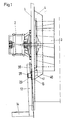
- a motor 2 is attached to a housing wall 1, the shaft of which through the housing wall 1 into the interior of the housing, not shown here, with a fan wheel 3 attached to this shaft.
- a fan surface 4 is provided concentrically surrounding the fan wheel 3, which partially closes with the housing wall 1 in the exemplary embodiment shown here.
- a discharge area 40 is provided in the lower area of the guide surface 4, which is opposite a housing opening 10 in the housing wall 1.
- the housing opening 10 can be closed by means of a flap 20 which can be moved via a lever mechanism, of which only one bracket 30 is shown here.
- Communicated with the housing opening 10, a shaft 12 is arranged, which is inclined slightly inwards relative to the housing wall 1 in the direction of the housing.
- the flap 20 runs on a shaft wall, sliding through a stud 28.
- the shaft 12 opens into an outlet 14. This is arranged essentially perpendicular to the shaft 12, so that moisture which condenses in the shaft 12 can run off due to gravity.
- Fig. 2 shows a second embodiment of a device according to the present invention in detail.
- the guide surface 4 is designed here so that it only surrounds the fan wheel 3 in a lower region. Otherwise, the structure corresponds to that of FIG. 1.
- a spring 29 provided on the stud 28 attached to the flap 20 ensures that the flap 20 is pressed onto the opening 10.
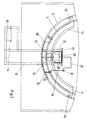
- the guide surface 4 has on its side facing the center of the arrangement a folded fold 44, which further concentrates the gas flow on the inside of the guide surface 4 causes.
- a partition 42 is arranged on the guide surface 4 in a substantially vertical direction.
- the flow generated by the fan wheel, not shown in FIG. 3, which propagates along the guide surface 4 is diverted at the partition 42 and guided in the direction of the housing opening 10.
- the guide surface 4 is fastened to the housing wall with flanges 46, 48, and fastening options can also be provided in the discharge area 40.
- 4 heating coils 5, 6 are arranged outside the guide surface.
- the flap 20 is connected to a bracket 30 of a lever mechanism, which is also connected to a linkage and additional required mechanism 36 via a pivot point 32.
- the entire control system both mechanical and electronic, can thus be arranged outside the housing in which the gas volume is located.
- a sliding aid 22 for the flap 20 is provided in the upper region of the shaft 12.
- the flap 20 itself runs trapezoidal. By means of the mechanics, it can be placed more or less far into the shaft 12, guided in rails 24, 26, the housing opening 10 being opened more or less in accordance with the specified specifications. Since the shaft 12 is generally at a lower temperature than the heated interior of the housing, the moisture precipitates in the shaft and runs into the outlet 14, from where it can be drained through an opening 16.
- the mechanism for lifting and lowering the flap 20 must be designed so that it ensures the trouble-free functioning of the device. However, there is no need for the limitation shown in FIG. 3.
- This device is preferably used to control the moisture content of a cooking chamber atmosphere. As soon as an excessively high moisture content is determined, the flap 20 is opened, the pressure built up by the guide surface 4 ensuring that the cooking chamber atmosphere is forced away. Dry air flowing in lowers the moisture content inside the cooking space. If the moisture content should remain constant or even be increased, the flap 20 is closed. If necessary, measures can be provided which make it possible to supply moisture specifically to the interior of the cooking space.
Abstract
Description
Die Erfindung betrifft eine Vorrichtung gemäß dem Oberbegriff des Patentanspruchs 1.The invention relates to a device according to the preamble of
Insbesondere beim Garen von stark wasserhaltigem Kochgut, dessen Wasser teilweise in die Garraumatmosphäre austritt, kann ein Überschuß an Feuchtigkeit auftreten, der oftmals nicht erwünscht ist, da er beispielsweise die Ausbildung einer Kruste auf dem zu garenden Gut verhindert. Es besteht daher die Notwendigkeit, zumindest von Zeit zu Zeit die entstehende Feuchtigkeit abzuführen.In particular when cooking food with a high water content, the water of which partially escapes into the cooking chamber atmosphere, an excess of moisture can occur, which is often not desirable because it prevents, for example, the formation of a crust on the food to be cooked. There is therefore a need to remove the resulting moisture at least from time to time.
Die tatsächlichen Möglichkeiten dazu sind beschränkt. Einfache Maßnahmen, wie das regelmäßige Öffnen der Tür des Garraumes, sind für Großküchen unakzeptabel, da keine reproduzierbaren Qualitäten gewährleistet werden können. An dem gleichen Mangel leiden einfach Abzüge über am Garraum vorgesehene Kamine. Zusätzlich getroffene Maßnahmen wie Absaugeinrichtungen oder dergleichen erfordern einen erhöhten apparativen Aufwand.The actual possibilities for this are limited. Simple measures, such as opening the cooking chamber door regularly, are unacceptable for commercial kitchens, as no reproducible qualities can be guaranteed. The same drawback simply suffers from fume cupboards over chimneys provided in the cooking space. Measures additionally taken, such as suction devices or the like, require an increased outlay on equipment.
Aus der DE-PS 21 03 593 ist eine Dunstabzugshaube für Küchen bekannt, bei der eine im wesentlichen radial gerichtete Strömung in dem in der Dunstabzugshaube vorhandenen Gasvolumen erzeugt. Das Radialgebläse ist dabei teilweise von einer Führungsfläche umgeben, wobei eine Gehäusewand vorgesehen ist, auf welche die Gasströmung in der Dunstabzugshaube mittels einer als Leitfläche dienenden Trennwand gerichtet wird. Eine einzelne Gaskomponente, wie Feuchtigkeit oder dergleichen, die im Überschuß vorhanden ist, aus dem Gasvolumen abzuführen, ist mit dieser Vorrichtung nich möglich.From DE-PS 21 03 593 an extractor hood for kitchens is known in which an essentially radially directed flow is generated in the gas volume present in the extractor hood. The radial fan is included partially surrounded by a guide surface, a housing wall being provided, onto which the gas flow in the extractor hood is directed by means of a partition serving as a guide surface. A single gas component, such as moisture or the like, which is present in excess, from the gas volume is not possible with this device.
Aus der DE-GM 85 34 653 ist eine Absperrschiebereinrichtung für Absauganlagen bekannt, bei der das Saugrohr im Nicht-Betriebszustand geschlossen werden kann. Dabei handelt es sich nicht um eine Vorrichtung, die bei Großküchengeräten oder dergleichen zum Abzug von z. B. überschüssiger Feuchtigkeit aus der Garraumatmosphäre verwendet werden könnte.From DE-GM 85 34 653 a gate valve device for suction systems is known in which the suction pipe can be closed in the non-operating state. It is not a device that can be used for deduction of z. B. excess moisture from the cooking cabinet atmosphere could be used.
Aus der EP-PS 03 01 640 ist eine Vorrichtung zum Abfübren einer Gaskomponente aus einem Garraum bekannt. Diese Vorrichtung weist ein Radialgebläse auf, welches in der Nähe an der im wesentlichen ebenen Gehäusewand angeordnet ist. Nahe dem Umfang des Lüfterrades ist eine Gehäuseöffnung zum Abfübren der Gaskomponente und eine Trennwand zum Umlenken der durch das Radialgebläse erzeugten Gasströmung auf die Gehäuseöffnung vorgesehen. Eine einzelne Gaskomponente, wie Feuchtigkeit und dergleichen, die im Überschuß vorhanden ist, aus dem Gasvolumen abzuführen, ist auch mit dieser Vorrichtung nicht möglich.From EP-PS 03 01 640 a device for removing a gas component from a cooking chamber is known. This device has a radial fan, which is arranged in the vicinity of the substantially flat housing wall. A housing opening for removing the gas component and a partition for deflecting the gas flow generated by the radial fan onto the housing opening are provided near the circumference of the fan wheel. A single gas component, such as moisture and the like, which is present in excess from the gas volume, is also not possible with this device.
Dementsprechend liegt der Erfindung die Aufgabe zugrunde, eine Vorrichtung der vorgenannten Art zu schaffen, mittels welcher aus dem Garraum eines Gargerätes eine bestimmte Gaskomponente, insbesondere Feuchtigkeit, teilweise abführbar ist.Accordingly, the invention has for its object to provide a device of the aforementioned type, by means of which a certain gas component, in particular moisture, can be partially removed from the cooking space of a cooking appliance.
Erfindungsgemäß wird diese Aufgabe dadurch gelöst, daß die Gehäusewand im wesentlichen vertikal angeordnet ist und einen Garraum eines Gargerätes begrenzt; daß die Gehäusewand von einer Antriebswelle eines auf der dem Radialgebläse abgewandten Seite der Gehäusewand außerhalb des Garraumes angeordneten Motors durchsetzt ist, die innerhalb des Garraumes das Lüfterrad trägt; und daß die Trennwand als lediglich einen Teil der durch das Radialgebläse erzeugten Strömung auf die Gehäuseöffnung richtende aerodynamische Leitfläche ausgebildet und nahe dem Umfang des Lüfterrades angeordnet ist.According to the invention, this object is achieved in that the housing wall is arranged essentially vertically and delimits a cooking space of a cooking appliance; that the housing wall is penetrated by a drive shaft of a motor arranged on the side of the housing wall facing away from the radial fan, said motor carrying the fan wheel inside the cooking chamber; and that the partition is formed as only a part of the flow generated by the radial fan directed towards the housing opening aerodynamic guide surface and is arranged near the circumference of the fan wheel.
Dabei kann vorgesehen sein, daß das Radialgebläse zumindest teilweise von einer Führungsfläche umgeben ist, die einen der Gehäuseöffnung benachbarten Ableitbereich umfaßt.It can be provided that the radial fan is at least partially surrounded by a guide surface which includes a discharge area adjacent to the housing opening.
Nach der Erfindung kann auch vorgesehen sein, daß die Führungsfläche im wesentlichen kreisringförmig ausgebildet ist.According to the invention it can also be provided that the guide surface is essentially circular is.
Eine weitere Ausführungsform der Erfindung sieht vor, daß die Führungsfläche die Form eines Hohlkegelstumpfes hat, der sich auf die Gehäusewand hin erweitert.Another embodiment of the invention provides that the guide surface has the shape of a hollow truncated cone which widens towards the housing wall.
Dabei kann auch vorgesehen sein, daß die Führungsfläche um den gesamten Umfang des Gebläses, jedoch das Gebläse höchstens teilweise in axialer Richtung überdeckend, angeordnet ist.It can also be provided that the guide surface is arranged around the entire circumference of the blower, but at most partially overlapping the blower in the axial direction.
Nach der Erfindung kann auch noch vorgesehen sein, daß die Gehäuseöffnung abhängig vom Gehalt des Gases an der überschüssigen Komponente wenigstens teilweise öffenbar und/oder schließbar ist.According to the invention it can also be provided that the housing opening can be at least partially opened and / or closed depending on the content of the gas in the excess component.
Eine weitere Ausführungsform der Erfindung sieht vor, daß zum Verschließen der Gehäuseöffnung wenigstens eine Klappe, ein Lamellenverschluß, ein irisblendenartiger Verschluß oder dergleichen vorgesehen ist.A further embodiment of the invention provides that at least one flap, a lamella closure, an iris-like closure or the like is provided for closing the housing opening.
Auch kann vorgesehen sein, daß die Klappe in Schienen geführt ist.It can also be provided that the flap is guided in rails.
Es kann auch noch vorgesehen sein, daß an der Klappe ein Stollen angebracht ist, welcher die Klappe im Schacht gleitend führt.It can also be provided that a stud is attached to the flap, which slides the flap in the shaft.
Eine weitere Ausführunsform der Erfindung sieht vor, daß sie einen relativ zu einer Gehäusewand, in der die Gehäuseöffnung vorgesehen ist, geneigten Schacht mit Ablauf aufweist, in den die Gehäuseöffnung mündet.A further embodiment of the invention provides that it has a shaft with an outlet which is inclined relative to a housing wall in which the housing opening is provided and into which the housing opening opens.
Dabei kann auch noch vorgesehen sein, daß die Trennwand mittig in bezug auf die Gehäuseöffnung angeordnet ist.It can also be provided that the partition is arranged centrally with respect to the housing opening.
Nach der Erfindung kann auch vorgesehen sein, daß die Trennwand als von der im wesentlichen kreisförmigen Gehäuseöffnung an der bezüglich der Drehachse des Radialgebläses radial außen liegenden Seite in Richtung auf das Radialgebläse vorstehende Teilringfläche ausgebildet ist.According to the invention it can also be provided that the dividing wall is designed as a partial ring surface projecting from the substantially circular housing opening on the side radially outward with respect to the axis of rotation of the radial fan in the direction of the radial fan.
Eine weitere Ausführungsform ist dadurch gekennzeichnet, daß die Trennwand im wesentlichen eben ausgebildet ist und in Radialrichtung des Radialgebläses verläuft.Another embodiment is characterized in that the partition is essentially flat and extends in the radial direction of the radial fan.
Dabei kann auch noch vorgesehen sein, daß die Trennwand pflugscharartig ausgebildet ist, wobei die Scharkante in einer die Achse des Radialgebläses enthaltenden Ebene liegt und die Scharflächen bezüglich der Drehachse des Radialgebläses divergierend nach außen verlaufen.It can also be provided that the partition is ploughshare-like, the share edge lying in a plane containing the axis of the radial fan and the share surfaces diverging with respect to the axis of rotation of the radial fan to the outside.
Schließlich kann nach der Erfindung auch vorgesehen sein, daß die Gehäuseöffnung zumindest teilweise von dem Radialgebläse überstrichen ist.Finally, it can also be provided according to the invention that the housing opening is at least partially swept by the radial fan.
Das Gebläse erzeugt bei der erfindungsgemäßen Vorrichtung eine Gasströmung, ggf. an der Innenseite der vorgesehenen Führungsfläche, die entsprechend dem Drehsinn gerichtet ist. Der Drehsinn des Gebläses kann dabei, insbesondere bei der Anwendung in Gargeräten, in regelmäßigen Zeitabständen gewechselt werden, so daß auch die Richtung der Gasströmung entsprechend wechselt. Es werden somit alternierend zwei an der Führungsfläche umlaufende Gasströme erzeugt. Das Gas wird dabei auf eine Trennwand im Ableitbereich gedrückt und kann durch eine Gehäuseöffnung aus dem Gehäuse abgeführt werden.In the device according to the invention, the fan produces a gas flow, possibly on the inside of the guide surface provided, which is directed in the direction of rotation. The direction of rotation of the fan can be changed at regular intervals, particularly when used in cooking appliances, so that the direction of the gas flow also changes accordingly. Two gas flows circulating on the guide surface are thus generated alternately. The gas is pressed onto a partition in the discharge area and can be discharged from the housing through a housing opening.
Falls eine Steuerung erwünscht ist, kann vorgesehen sein, daß die Gehäuseöffnung abhängig vom Gehalt des Gases an der überschüssigen Komponente wenigstens teilweise öffenbar und/oder schließbar ist. Die Steuerung kann beispielsweise mittels des Verfahrens durchgeführt werden, das in der deutschen Patentanmeldung P 42 06 845.2-52 (am 09.09.93 veroffentlicht) beschrieben ist.If control is desired, it can be provided that the housing opening can be at least partially opened depending on the content of the gas in the excess component and / or is closable. The control can be carried out, for example, using the method described in German
Grundsätzlich ist es nicht notwendig, daß die Führungsfläche um den gesamten Umfang des Gebläses geführt ist, solange nur gewährleistet ist, daß sich die Strömung mit den gewünschten Eigenschaften ausbildet. Es kann jedoch vorteilhaft sein, die Führungsfläche um den gesamten Umfang des Gebläses, jedoch das Gebläse höchstens teilweise in axialer Richtung überdeckend anzuordnen.In principle, it is not necessary for the guide surface to be guided around the entire circumference of the fan, as long as it is only ensured that the flow develops with the desired properties. However, it can be advantageous to arrange the guide surface over the entire circumference of the blower, but at most partially overlapping the blower in the axial direction.
Zum Verschließen der Gehäuseöffnung kann wenigstens eine Klappe, ein Lamellenverschluß, ein irisblendenartiger Verschluß oder dergleichen vorgesehen sein. Für die Anordnung der Klappe gibt es dabei die Möglichkeit, sie entweder vertikal verschiebbar anzuordnen oder aber vorzusehen, daß zwei Klappen sich nach Art einer doppelflügligen Schiebetür aufeinander zu oder voneinander weg bewegen.At least one flap, a lamella closure, an iris-like closure or the like can be provided to close the housing opening. For the arrangement of the flap there is the possibility either to arrange it vertically or to provide that two flaps move towards or away from each other in the manner of a double-leaf sliding door.
Das Ableiten des Gases mit der zu entfernenden Gaskomponente erfolgt effektiv, wenn die Vorrichtung einen relativ zur Gehäusewand, in der die Gehäuseöffnung vorgesehen ist, geneigten Schacht mit Ablauf aufweist, in den die Gehäuseöffnung mündet.The discharge of the gas with the gas component to be removed takes place effectively if the device has a shaft with an outlet which is inclined relative to the housing wall in which the housing opening is provided and into which the housing opening opens.
Um die Öffnung im wesentlichen gasdicht verschließen zu können, kann die Klappe in entsprechend ausgebildeten Schienen geführt sein.In order to be able to close the opening in a substantially gas-tight manner, the flap can be guided in appropriately designed rails.
Wenn weiterhin an die Klappe ein Stollen angebracht ist, welcher die Klappe im Schacht gleitend führt, kann weiterhin erreicht werden, daß, beispielsweise durch Eigenelastizität des Stollens oder einer zusätzlich am Stollen vorgesehenen Feder, ein Andruck der Klappe auf den Öffnungsbereich ausgeübt wird.If a cleat is also attached to the flap, which slides the flap in the shaft, it can also be achieved that, for example, by the cleat's own elasticity or one additionally on the cleat provided spring, a pressure of the flap is exerted on the opening area.
Schließlich ist es für ein Gebläse mit sich änderndem Drehsinn besonders bevorzugt, wenn zum Umleiten der Gasströmung von der Führungsfläche zur Gehäuseöffnung im Ableitbereich die Trennwand mittig in bezug auf die Gehäuseöffnung angeordnet ist.Finally, for a blower with a changing direction of rotation, it is particularly preferred if, in order to divert the gas flow from the guide surface to the housing opening in the discharge area, the partition is arranged centrally with respect to the housing opening.
Es sei darauf hingewiesen, daß ein wesentliches Merkmal des Erfindungsgedankens daran liegt, daß selbst dann, wenn keine das Radialgebläse umgebende Führungsfläche vorgesehen ist, mittels der als aerodynamische Leitfläche dienenden Trennwand in gewünschtem Ausmaß ein Gasstrom auf die Gehäuseöffnung hin gerichtet werden kann, so daß also beispielsweise je nach Bedarf Feuchtigkeit mit dem abgetrennten Gasvolumen aus der Garraumatmosphäre oder dergleichen entfernbar ist.It should be pointed out that an essential feature of the inventive concept is that even if no guide surface surrounding the radial fan is provided, a gas flow can be directed towards the housing opening to the desired extent by means of the partition serving as an aerodynamic guide surface, so that for example, moisture can be removed from the cooking space atmosphere or the like with the separated gas volume as required.
Weitere Merkmale und Vorteile der Erfindung ergeben sich aus den Ansprüchen und aus der nachstehenden Beschreibung, in der Ausführungsbeispiele anhand der schematischen Zeichnung im einzelnen erläutert sind. Dabei zeigt:
- Fig. 1
- eine schematische Darstellung einer ersten Ausführungsform einer Vorrichtung gemäß der vorliegenden Erfindung im Querschnitt; und
- Fig. 2
- eine Detaildarstellung einer zweiten Ausführungsform der Vorrichtung gemäß der vorliegenden Erfindung im Querschnitt; und
- Fig. 3
- eine Draufsicht, schematich dargestellt, auf eine Vorrichtung gemäß der vorliegenden Erfindung.
- Fig. 1
- a schematic representation of a first embodiment of a device according to the present invention in cross section; and
- Fig. 2
- a detailed view of a second embodiment of the device according to the present invention in cross section; and
- Fig. 3
- a plan view, shown schematically, on a device according to the present invention.
In Fig. 1 ist an einer Gehäusewand 1 ein Motor 2 angebracht, dessen Welle durch die Gehäusewand 1 in das Innere des hier nicht dargestellten Gehäuses ragt, wobei auf dieser Welle ein Lüfterrad 3 angebracht ist. Das Lüfterrad 3 konzentrisch umschließend ist eine Führungsfläche 4 vorgesehen, die im hier dargestellten Ausführungsbeispiel teilweise mit der Gehäusewand 1 abschließt. Im unteren Bereich der Führungsfläche 4 ist ein Ableitbereich 40 vorgesehen, der einer Gehäuseöffnung 10 in der Gehäusewand 1 gegenüberliegt. Die Gehäuseöffnung 10 kann mittels einer Klappe 20 verschlossen werden, die über einen Hebelmechanismus bewegbar ist, von dem hier nur ein Bügel 30 dargestellt ist. Mit der Gehäuseöffnung 10 kommuniziert ist ein Schacht 12 angeordnet, der relativ zur Gehäusewand 1 leicht nach innen, in Richtung auf das Gehäuse zu, geneigt ist. In diesem Schacht 12 läuft die Klappe 20, gleitend durch einen Stollen 28, an einer Schachtwand abgestützt. Der Schacht 12 mündet in einem Ablauf 14. Dieser ist im wesentlichen senkrecht zum Schacht 12 angeordnet, so daß sich im Schacht 12 niederschlagende Feuchtigkeit aufgrund der Schwerkraft ablaufen kann.In Fig. 1, a
Fig. 2 zeigt eine zweite Ausführungsform einer Vorrichtung gemäß der vorliegenden Erfindung im Detail. Im Unterschied zu der Ausführungsform nach Fig. 1 ist hier die Führungsfläche 4 so ausgebildet, daß sie das Lüfterrad 3 lediglich in einem unteren Bereich umgibt. Ansonsten entspricht der Aufbau dem der Fig. 1. Hier ist besonders deutlich zu erkennen, wie eine auf dem an der Klappe 20 angebrachten Stollen 28 vorgesehene Feder 29 für einen Andrucksitz der Klappe 20 auf der Öffnung 10 sorgt.Fig. 2 shows a second embodiment of a device according to the present invention in detail. In contrast to the embodiment according to FIG. 1, the guide surface 4 is designed here so that it only surrounds the fan wheel 3 in a lower region. Otherwise, the structure corresponds to that of FIG. 1. Here it can be seen particularly clearly how a
Weitere Einzelheiten der erfindungsgemäßen Vorrichtung sind Fig. 3 zu entnehmen. Die Führungsfläche 4 weist an ihrer zum Zentrum der Anordnung gerichteten Seite einen umgeschlagenen Falz 44 auf, der eine weitere Konzentrierung der Gasströmung an der Innenseite der Führungsfläche 4 bewirkt. Gegenüber der Gehäuseöffnung 10 ist an der Führungsfläche 4 eine Trennwand 42 in im wesentlichen vertikaler Richtung angeordnet. Die von dem in Fig. 3 nicht dargestellten Lüfterrad erzeugte Strömung, die sich entlang der Führungsfläche 4 fortpflanzt, wird an der Trennwand 42 umgeleitet und in Richtung auf die Gehäuseöffnung 10 geführt. Die Führungsfläche 4 ist mit Flanschen 46, 48 an der Gehäusewand befestigt, zusätzlich können Befestigungsmöglichkeiten im Ableitbereich 40 vorgesehen sein. Im hier dargestellten Beispiel, gemäß dem die Vorrichtung in einem Gargerät zur Anwendung kommen soll, sind außerhalb der Führungsfläche 4 Heizschlangen 5, 6 angeordnet. Die Klappe 20 ist mit einem Bügel 30 eines Hebelmechanismus verbunden, der über einen Anlenkpunkt 32 weiterhin mit einem Gestänge und zusätzlicher erforderlicher Mechanik 36 in Verbindung steht. Die gesamte Steuerung, sowohl die mechanische als auch die elektronische, kann damit außerhalb des Gehäuses, in dem das Gasvolumen sich befindet, angeordnet werden. Im oberen Bereich des Schachtes 12 ist eine Gleithilfe 22 für die Klappe 20 vorgesehen. Die Klappe 20 selbst läuft trapezförmig aus. Sie kann mittels der Mechanik mehr oder weniger weit in den Schacht 12 abgesetzt werden, in Schienen 24, 26 geführt, wobei die Gehäuseöffnung 10 entsprechend den vorgegebenen Spezifikationen mehr oder weniger geöffnet wird. Da der Schacht 12 sich im allgemeinen auf einer niedrigeren Temperatur befindet als das beheizte Gehäuseinnere, fällt die Feuchtigkeit im Schacht aus und rinnt in den Ablauf 14, von wo sie über eine Öffnung 16 abgelassen werden kann.3 shows further details of the device according to the invention. The guide surface 4 has on its side facing the center of the arrangement a folded
Die Mechanik zum Anheben und Absenken der Klappe 20 muß so ausgelegt sein, daß sie das störungsfreie Funktionieren der Vorrichtung gewährleistet. Eine Notwendigkeit auf die Bschränkung nach der Fig. 3 gezeigten Ausführungsform besteht dabei jedoch nicht.The mechanism for lifting and lowering the
Bevorzugt wird diese Vorrichtung zum Steuern des Feuchtigkeitsgehaltes einer Garraumatmosphäre eingesetzt. Sobald ein zu hoher Feuchtigkeitsgehalt festgestellt wird, wird die Klappe 20 geöffnet, wobei der durch die Führungsfläche 4 aufgebaute Druck für eine Zwangabführung von Garraumatmosphäre sorgt. Trockene nachströmende Luft senkt den Feuchtigkeitsgehalt im Inneren des Garraumes. Soll der Feuchtigkeitsgehalt konstant bleiben oder sogar erhöht werden, wird die Klappe 20 geschlossen. Es können gegebenenfalls Maßnahmen vorgesehen sein, die es ermöglichen, gezielt Feuchtigkeit dem Garrauminneren zuzuführen.This device is preferably used to control the moisture content of a cooking chamber atmosphere. As soon as an excessively high moisture content is determined, the
- 11
- GehäusewandHousing wall
- 22nd
- Motorengine
- 33rd
- LüfterradFan wheel
- 44th
- FührungsflächeLeadership area
- 1010th
- GehäuseöffnungHousing opening
- 1212th
- SchachtShaft
- 1414
- Ablaufprocedure
- 1616
- AuslaßöffnungOutlet opening
- 2020th
- Klappeflap
- 2222
- GleithilfeSliding aid
- 2424th
- FührungsschieneGuide rail
- 2626
- FührungsschieneGuide rail
- 2828
- Stollenstollen
- 3030th
- Bügelhanger
- 3232
- AnlenkpunktPivot point
- 3434
- HebelarmLever arm
- 3636
- Mechanikmechanics
- 4040
- AbleitbereichDischarge area
- 4242
- Trennwandpartition wall
- 4444
- FalzFold
- 4646
- Flanschflange
- 4848
- Flanschflange
Claims (15)
- A device for discharging a gaseous component from a cooking-chamber atmosphere and comprising a radial fan comprising a rotor (3) and disposed near a substantially flat casing wall (1), an opening (10) in the wall (1) for discharging the gaseous component near the periphery of the rotor (3), and a partition (42) for guiding the gas flow generated by the radial fan towards the opening (10), characterised in that the wall (1) is substantially vertical and bounds a cooking chamber in a cooker; in that a driving shaft of a motor (2) disposed on the side of the wall (1) remote from the radial fan and outside the cooking chamber extends through the wall (1) and bears the rotor (3) inside the cooking chamber; and in that the partition (42) is constructed simply as a part of the aerodynamic guide surface directing the flow generated by the fan towards the opening (10) and is disposed near the periphery of the rotor (3).
- A device according to claim 1, characterised in that the radial fan (3) is at least partly surrounded by a guide surface (4) comprising a drainage region (40) adjacent the opening (10).
- A device according to claim 2, characterised in that the guide surface (4) is substantially in the form of a circular ring.
- A device according to claim 2, characterised in that the guide surface (4) is in the form of a hollow truncated cone which widens towards the casing wall (1).
- A device according to any of claims 2 to 4, characterised in that the guide surface (4) is disposed around the entire periphery of the fan (3) but overlaps the fan (3) only partly in the axial direction, if at all.
- A device according to any of the preceding claims, characterised in that the opening (10) in the casing can be at least partly opened and/or closed depending on the content of the excess component in the gas.
- A device according to claim 6, characterised in that at least one valve (20) or lamellar shutter or iris diaphragm-like shutter or similar is provided for closing the opening (10).
- A device according to claim 7, characterised in that the valve (20) is guided on rails (24, 26).
- A device according to claim 7 or 8, characterised in that a stud, support or the like (28) is disposed on the valve (20) and slidingly guides the valve (20) in the shaft (12).
- A device according to any of the preceding claims, characterised in that it comprises a shaft (12) inclined relatively to a casing wall (1) formed with the opening (10), said shaft (12) having an outlet (14) and having the opening (10) leading into said shaft (12).
- A device according to any of the preceding claims, characterised in that the partition (42) is centrally disposed relative to the opening (10).
- A device according to any of the preceding claims, characterised in that the partition (42) is in the form of a part-annular surface projecting from the substantially circular opening (10) towards the radial fan (3) on the radially outer side relative to the axis of rotation of the radial fan (3).
- A device according to any of claims 1 to 11, characterised in that the partition (42) is substantially flat and extends in the radial direction of the radial fan (3).
- A device according to any of claims 1 to 11, characterised in that the partition (42) is ploughshare-shaped, the edge of the share lies in a plane containing the axis of the radial fan (3) and the surfaces of the share diverge outwards relative to the axis of rotation of the fan (3).
- A device according to any of the preceding claims, characterised in that the opening (10) is swept at least partly by the radial fan (3).
Priority Applications (2)
| Application Number | Priority Date | Filing Date | Title |
|---|---|---|---|
| US08/025,999 US5370498A (en) | 1992-03-04 | 1993-03-04 | Apparatus for elimination of gas constituents |
| JP04407393A JP3437597B2 (en) | 1992-03-04 | 1993-03-04 | Gas component removal device |
Applications Claiming Priority (2)
| Application Number | Priority Date | Filing Date | Title |
|---|---|---|---|
| DE4206847 | 1992-03-04 | ||
| DE4206847 | 1992-03-04 |
Publications (2)
| Publication Number | Publication Date |
|---|---|
| EP0559080A1 EP0559080A1 (en) | 1993-09-08 |
| EP0559080B1 true EP0559080B1 (en) | 1996-11-20 |
Family
ID=6453225
Family Applications (1)
| Application Number | Title | Priority Date | Filing Date |
|---|---|---|---|
| EP93102950A Expired - Lifetime EP0559080B1 (en) | 1992-03-04 | 1993-02-25 | Device for exhausting of a gas-component |
Country Status (6)
| Country | Link |
|---|---|
| EP (1) | EP0559080B1 (en) |
| AT (1) | ATE145468T1 (en) |
| DE (1) | DE59304500D1 (en) |
| DK (1) | DK0559080T3 (en) |
| ES (1) | ES2094392T3 (en) |
| GR (1) | GR3021756T3 (en) |
Families Citing this family (1)
| Publication number | Priority date | Publication date | Assignee | Title |
|---|---|---|---|---|
| DE59701287D1 (en) * | 1997-12-23 | 2000-04-20 | Eloma Gmbh Groskuechentechnik | Method for dehumidifying a cooking space of a steam cooker and device therefor |
Family Cites Families (2)
| Publication number | Priority date | Publication date | Assignee | Title |
|---|---|---|---|---|
| SE353142B (en) * | 1970-01-30 | 1973-01-22 | N Bergmark | |
| IT1222139B (en) * | 1987-07-27 | 1990-09-05 | Elica Spa | FUME EXTRACTION HOOD, ESPECIALLY FOR DOMESTIC KITCHENS, AT A LARGE CAPACITY AERIAL |
-
1993
- 1993-02-25 AT AT93102950T patent/ATE145468T1/en not_active IP Right Cessation
- 1993-02-25 EP EP93102950A patent/EP0559080B1/en not_active Expired - Lifetime
- 1993-02-25 ES ES93102950T patent/ES2094392T3/en not_active Expired - Lifetime
- 1993-02-25 DK DK93102950.8T patent/DK0559080T3/en active
- 1993-02-25 DE DE59304500T patent/DE59304500D1/en not_active Expired - Fee Related
-
1996
- 1996-11-21 GR GR960403079T patent/GR3021756T3/en unknown
Also Published As
| Publication number | Publication date |
|---|---|
| ATE145468T1 (en) | 1996-12-15 |
| EP0559080A1 (en) | 1993-09-08 |
| GR3021756T3 (en) | 1997-02-28 |
| DK0559080T3 (en) | 1997-05-05 |
| ES2094392T3 (en) | 1997-01-16 |
| DE59304500D1 (en) | 1997-01-02 |
Similar Documents
| Publication | Publication Date | Title |
|---|---|---|
| EP0926449B2 (en) | Method for dehumidifying a cooking room of a steam cooking apparatus and apparatus therefor | |
| DE2837543A1 (en) | Fume hood | |
| EP3505830A1 (en) | Vapour extraction device for removing cooking vapours downwards | |
| DE202012013527U1 (en) | Mounting unit with hob and extractor device | |
| EP3045824B1 (en) | Device for drawing off exhaust air of a cooker hob | |
| EP0598211A1 (en) | Oven, in particular pyrolytic self-cleaning oven | |
| EP2476960B1 (en) | Switching device for an extractor hood for switching between circulation and extraction | |
| EP3686496B1 (en) | Vapour hood and method for changing filter units | |
| DE3246333C2 (en) | ||
| DE2006621C2 (en) | Oven and roasting tube | |
| EP2857758B1 (en) | Vapor extraction device | |
| EP2653787B1 (en) | table fan device | |
| EP0072377B1 (en) | Device for delivering a substance which removes odour from the air, in particular for kitchen hoods | |
| EP3276265A1 (en) | Household appliance | |
| EP0559080B1 (en) | Device for exhausting of a gas-component | |
| DE202007007450U1 (en) | Retract absorption equipment e.g. for oven, has area having drawer-like lockable door and which is rigidly fastened to pair of sliding courses | |
| DE4445594A1 (en) | Air channel for baking oven | |
| EP0671591A1 (en) | Device for removing cooking fumes from a baking oven | |
| EP0017790B1 (en) | Vapour extraction hood to be fitted over kitchen ranges | |
| EP0491166A1 (en) | Fume hood | |
| DE4206846A1 (en) | Sepn. device for solid and liq. particles in an enclosed air vol. - e.g. in a fan assisted oven, comprises 1st impingement baffle where (some of) solid and/or liq. is removed and device imposing directional bias on the flow | |
| DE2417327A1 (en) | COATING SYSTEM FOR MANHOLE FURNACES | |
| DE10245464A1 (en) | oven | |
| DE10207638B4 (en) | Hot air oven with improved door seal | |
| DE19825322A1 (en) | Oven with flow guide |
Legal Events
| Date | Code | Title | Description |
|---|---|---|---|
| PUAI | Public reference made under article 153(3) epc to a published international application that has entered the european phase |
Free format text: ORIGINAL CODE: 0009012 |
|
| AK | Designated contracting states |
Kind code of ref document: A1 Designated state(s): AT BE CH DE DK ES FR GB GR IE IT LI LU NL PT SE |
|
| 17P | Request for examination filed |
Effective date: 19940210 |
|
| 17Q | First examination report despatched |
Effective date: 19941021 |
|
| GRAG | Despatch of communication of intention to grant |
Free format text: ORIGINAL CODE: EPIDOS AGRA |
|
| GRAH | Despatch of communication of intention to grant a patent |
Free format text: ORIGINAL CODE: EPIDOS IGRA |
|
| GRAH | Despatch of communication of intention to grant a patent |
Free format text: ORIGINAL CODE: EPIDOS IGRA |
|
| GRAA | (expected) grant |
Free format text: ORIGINAL CODE: 0009210 |
|
| ITF | It: translation for a ep patent filed |
Owner name: FUMERO BREVETTI S.N.C. |
|
| AK | Designated contracting states |
Kind code of ref document: B1 Designated state(s): AT BE CH DE DK ES FR GB GR IE IT LI LU NL PT SE |
|
| REF | Corresponds to: |
Ref document number: 145468 Country of ref document: AT Date of ref document: 19961215 Kind code of ref document: T |
|
| ET | Fr: translation filed | ||
| REG | Reference to a national code |
Ref country code: CH Ref legal event code: NV Representative=s name: BUECHEL & PARTNER AG PATENTBUERO |
|
| GBT | Gb: translation of ep patent filed (gb section 77(6)(a)/1977) |
Effective date: 19961122 |
|
| REG | Reference to a national code |
Ref country code: IE Ref legal event code: FG4D Free format text: 70683 |
|
| REF | Corresponds to: |
Ref document number: 59304500 Country of ref document: DE Date of ref document: 19970102 |
|
| REG | Reference to a national code |
Ref country code: ES Ref legal event code: FG2A Ref document number: 2094392 Country of ref document: ES Kind code of ref document: T3 |
|
| REG | Reference to a national code |
Ref country code: GR Ref legal event code: FG4A Free format text: 3021756 |
|
| REG | Reference to a national code |
Ref country code: DK Ref legal event code: T3 |
|
| PLBE | No opposition filed within time limit |
Free format text: ORIGINAL CODE: 0009261 |
|
| STAA | Information on the status of an ep patent application or granted ep patent |
Free format text: STATUS: NO OPPOSITION FILED WITHIN TIME LIMIT |
|
| 26N | No opposition filed | ||
| PGFP | Annual fee paid to national office [announced via postgrant information from national office to epo] |
Ref country code: ES Payment date: 20010131 Year of fee payment: 9 |
|
| PGFP | Annual fee paid to national office [announced via postgrant information from national office to epo] |
Ref country code: PT Payment date: 20010202 Year of fee payment: 9 |
|
| PGFP | Annual fee paid to national office [announced via postgrant information from national office to epo] |
Ref country code: DK Payment date: 20010213 Year of fee payment: 9 Ref country code: AT Payment date: 20010213 Year of fee payment: 9 |
|
| PGFP | Annual fee paid to national office [announced via postgrant information from national office to epo] |
Ref country code: IE Payment date: 20010221 Year of fee payment: 9 |
|
| PGFP | Annual fee paid to national office [announced via postgrant information from national office to epo] |
Ref country code: LU Payment date: 20010227 Year of fee payment: 9 |
|
| PGFP | Annual fee paid to national office [announced via postgrant information from national office to epo] |
Ref country code: GR Payment date: 20010228 Year of fee payment: 9 |
|
| PGFP | Annual fee paid to national office [announced via postgrant information from national office to epo] |
Ref country code: CH Payment date: 20010302 Year of fee payment: 9 |
|
| PGFP | Annual fee paid to national office [announced via postgrant information from national office to epo] |
Ref country code: BE Payment date: 20010420 Year of fee payment: 9 |
|
| REG | Reference to a national code |
Ref country code: GB Ref legal event code: IF02 |
|
| PG25 | Lapsed in a contracting state [announced via postgrant information from national office to epo] |
Ref country code: LU Free format text: LAPSE BECAUSE OF NON-PAYMENT OF DUE FEES Effective date: 20020225 Ref country code: IE Free format text: LAPSE BECAUSE OF NON-PAYMENT OF DUE FEES Effective date: 20020225 Ref country code: AT Free format text: LAPSE BECAUSE OF NON-PAYMENT OF DUE FEES Effective date: 20020225 |
|
| PG25 | Lapsed in a contracting state [announced via postgrant information from national office to epo] |
Ref country code: ES Free format text: LAPSE BECAUSE OF NON-PAYMENT OF DUE FEES Effective date: 20020226 |
|
| PG25 | Lapsed in a contracting state [announced via postgrant information from national office to epo] |
Ref country code: LI Free format text: LAPSE BECAUSE OF NON-PAYMENT OF DUE FEES Effective date: 20020228 Ref country code: DK Free format text: LAPSE BECAUSE OF NON-PAYMENT OF DUE FEES Effective date: 20020228 Ref country code: CH Free format text: LAPSE BECAUSE OF NON-PAYMENT OF DUE FEES Effective date: 20020228 Ref country code: BE Free format text: LAPSE BECAUSE OF NON-PAYMENT OF DUE FEES Effective date: 20020228 |
|
| BERE | Be: lapsed |
Owner name: RATIONAL G.M.B.H. Effective date: 20020228 |
|
| PG25 | Lapsed in a contracting state [announced via postgrant information from national office to epo] |
Ref country code: PT Free format text: LAPSE BECAUSE OF NON-PAYMENT OF DUE FEES Effective date: 20020831 |
|
| PG25 | Lapsed in a contracting state [announced via postgrant information from national office to epo] |
Ref country code: GR Free format text: LAPSE BECAUSE OF NON-PAYMENT OF DUE FEES Effective date: 20020909 |
|
| REG | Reference to a national code |
Ref country code: DK Ref legal event code: EBP |
|
| REG | Reference to a national code |
Ref country code: CH Ref legal event code: PL |
|
| REG | Reference to a national code |
Ref country code: PT Ref legal event code: MM4A Free format text: LAPSE DUE TO NON-PAYMENT OF FEES Effective date: 20020831 |
|
| REG | Reference to a national code |
Ref country code: IE Ref legal event code: MM4A |
|
| PGFP | Annual fee paid to national office [announced via postgrant information from national office to epo] |
Ref country code: NL Payment date: 20030226 Year of fee payment: 11 |
|
| REG | Reference to a national code |
Ref country code: ES Ref legal event code: FD2A Effective date: 20031022 |
|
| PG25 | Lapsed in a contracting state [announced via postgrant information from national office to epo] |
Ref country code: NL Free format text: LAPSE BECAUSE OF NON-PAYMENT OF DUE FEES Effective date: 20040901 |
|
| NLV4 | Nl: lapsed or anulled due to non-payment of the annual fee |
Effective date: 20040901 |
|
| PGFP | Annual fee paid to national office [announced via postgrant information from national office to epo] |
Ref country code: SE Payment date: 20060207 Year of fee payment: 14 |
|
| PGFP | Annual fee paid to national office [announced via postgrant information from national office to epo] |
Ref country code: FR Payment date: 20060220 Year of fee payment: 14 |
|
| PGFP | Annual fee paid to national office [announced via postgrant information from national office to epo] |
Ref country code: GB Payment date: 20060222 Year of fee payment: 14 |
|
| PG25 | Lapsed in a contracting state [announced via postgrant information from national office to epo] |
Ref country code: SE Free format text: LAPSE BECAUSE OF NON-PAYMENT OF DUE FEES Effective date: 20070226 |
|
| EUG | Se: european patent has lapsed | ||
| GBPC | Gb: european patent ceased through non-payment of renewal fee |
Effective date: 20070225 |
|
| REG | Reference to a national code |
Ref country code: FR Ref legal event code: ST Effective date: 20071030 |
|
| PG25 | Lapsed in a contracting state [announced via postgrant information from national office to epo] |
Ref country code: GB Free format text: LAPSE BECAUSE OF NON-PAYMENT OF DUE FEES Effective date: 20070225 Ref country code: FR Free format text: LAPSE BECAUSE OF NON-PAYMENT OF DUE FEES Effective date: 20070228 |
|
| PGFP | Annual fee paid to national office [announced via postgrant information from national office to epo] |
Ref country code: IT Payment date: 20080226 Year of fee payment: 16 |
|
| PGFP | Annual fee paid to national office [announced via postgrant information from national office to epo] |
Ref country code: DE Payment date: 20090226 Year of fee payment: 17 |
|
| PG25 | Lapsed in a contracting state [announced via postgrant information from national office to epo] |
Ref country code: DE Free format text: LAPSE BECAUSE OF NON-PAYMENT OF DUE FEES Effective date: 20100901 |
|
| PG25 | Lapsed in a contracting state [announced via postgrant information from national office to epo] |
Ref country code: IT Free format text: LAPSE BECAUSE OF NON-PAYMENT OF DUE FEES Effective date: 20090225 |