EP0559057A1 - Electrical connector terminal - Google Patents
Electrical connector terminal Download PDFInfo
- Publication number
- EP0559057A1 EP0559057A1 EP93102824A EP93102824A EP0559057A1 EP 0559057 A1 EP0559057 A1 EP 0559057A1 EP 93102824 A EP93102824 A EP 93102824A EP 93102824 A EP93102824 A EP 93102824A EP 0559057 A1 EP0559057 A1 EP 0559057A1
- Authority
- EP
- European Patent Office
- Prior art keywords
- contact
- terminal
- electric connector
- connecting piece
- beams
- Prior art date
- Legal status (The legal status is an assumption and is not a legal conclusion. Google has not performed a legal analysis and makes no representation as to the accuracy of the status listed.)
- Granted
Links
Images


Classifications
-
- H—ELECTRICITY
- H01—ELECTRIC ELEMENTS
- H01R—ELECTRICALLY-CONDUCTIVE CONNECTIONS; STRUCTURAL ASSOCIATIONS OF A PLURALITY OF MUTUALLY-INSULATED ELECTRICAL CONNECTING ELEMENTS; COUPLING DEVICES; CURRENT COLLECTORS
- H01R13/00—Details of coupling devices of the kinds covered by groups H01R12/70 or H01R24/00 - H01R33/00
- H01R13/02—Contact members
- H01R13/10—Sockets for co-operation with pins or blades
- H01R13/11—Resilient sockets
- H01R13/115—U-shaped sockets having inwardly bent legs, e.g. spade type
-
- H—ELECTRICITY
- H01—ELECTRIC ELEMENTS
- H01R—ELECTRICALLY-CONDUCTIVE CONNECTIONS; STRUCTURAL ASSOCIATIONS OF A PLURALITY OF MUTUALLY-INSULATED ELECTRICAL CONNECTING ELEMENTS; COUPLING DEVICES; CURRENT COLLECTORS
- H01R13/00—Details of coupling devices of the kinds covered by groups H01R12/70 or H01R24/00 - H01R33/00
- H01R13/02—Contact members
- H01R13/10—Sockets for co-operation with pins or blades
- H01R13/11—Resilient sockets
- H01R13/114—Resilient sockets co-operating with pins or blades having a square transverse section
-
- H—ELECTRICITY
- H01—ELECTRIC ELEMENTS
- H01R—ELECTRICALLY-CONDUCTIVE CONNECTIONS; STRUCTURAL ASSOCIATIONS OF A PLURALITY OF MUTUALLY-INSULATED ELECTRICAL CONNECTING ELEMENTS; COUPLING DEVICES; CURRENT COLLECTORS
- H01R12/00—Structural associations of a plurality of mutually-insulated electrical connecting elements, specially adapted for printed circuits, e.g. printed circuit boards [PCB], flat or ribbon cables, or like generally planar structures, e.g. terminal strips, terminal blocks; Coupling devices specially adapted for printed circuits, flat or ribbon cables, or like generally planar structures; Terminals specially adapted for contact with, or insertion into, printed circuits, flat or ribbon cables, or like generally planar structures
- H01R12/70—Coupling devices
- H01R12/71—Coupling devices for rigid printing circuits or like structures
- H01R12/712—Coupling devices for rigid printing circuits or like structures co-operating with the surface of the printed circuit or with a coupling device exclusively provided on the surface of the printed circuit
- H01R12/716—Coupling device provided on the PCB
-
- H—ELECTRICITY
- H01—ELECTRIC ELEMENTS
- H01R—ELECTRICALLY-CONDUCTIVE CONNECTIONS; STRUCTURAL ASSOCIATIONS OF A PLURALITY OF MUTUALLY-INSULATED ELECTRICAL CONNECTING ELEMENTS; COUPLING DEVICES; CURRENT COLLECTORS
- H01R12/00—Structural associations of a plurality of mutually-insulated electrical connecting elements, specially adapted for printed circuits, e.g. printed circuit boards [PCB], flat or ribbon cables, or like generally planar structures, e.g. terminal strips, terminal blocks; Coupling devices specially adapted for printed circuits, flat or ribbon cables, or like generally planar structures; Terminals specially adapted for contact with, or insertion into, printed circuits, flat or ribbon cables, or like generally planar structures
- H01R12/70—Coupling devices
- H01R12/71—Coupling devices for rigid printing circuits or like structures
- H01R12/72—Coupling devices for rigid printing circuits or like structures coupling with the edge of the rigid printed circuits or like structures
- H01R12/73—Coupling devices for rigid printing circuits or like structures coupling with the edge of the rigid printed circuits or like structures connecting to other rigid printed circuits or like structures
-
- H—ELECTRICITY
- H01—ELECTRIC ELEMENTS
- H01R—ELECTRICALLY-CONDUCTIVE CONNECTIONS; STRUCTURAL ASSOCIATIONS OF A PLURALITY OF MUTUALLY-INSULATED ELECTRICAL CONNECTING ELEMENTS; COUPLING DEVICES; CURRENT COLLECTORS
- H01R13/00—Details of coupling devices of the kinds covered by groups H01R12/70 or H01R24/00 - H01R33/00
- H01R13/02—Contact members
- H01R13/22—Contacts for co-operating by abutting
- H01R13/24—Contacts for co-operating by abutting resilient; resiliently-mounted
- H01R13/2464—Contacts for co-operating by abutting resilient; resiliently-mounted characterized by the contact point
-
- H—ELECTRICITY
- H01—ELECTRIC ELEMENTS
- H01R—ELECTRICALLY-CONDUCTIVE CONNECTIONS; STRUCTURAL ASSOCIATIONS OF A PLURALITY OF MUTUALLY-INSULATED ELECTRICAL CONNECTING ELEMENTS; COUPLING DEVICES; CURRENT COLLECTORS
- H01R12/00—Structural associations of a plurality of mutually-insulated electrical connecting elements, specially adapted for printed circuits, e.g. printed circuit boards [PCB], flat or ribbon cables, or like generally planar structures, e.g. terminal strips, terminal blocks; Coupling devices specially adapted for printed circuits, flat or ribbon cables, or like generally planar structures; Terminals specially adapted for contact with, or insertion into, printed circuits, flat or ribbon cables, or like generally planar structures
- H01R12/50—Fixed connections
- H01R12/51—Fixed connections for rigid printed circuits or like structures
- H01R12/55—Fixed connections for rigid printed circuits or like structures characterised by the terminals
- H01R12/57—Fixed connections for rigid printed circuits or like structures characterised by the terminals surface mounting terminals
Definitions
- the present invention relates generally to a female terminal for an electric connector. More specifically, the invention relates to an improvement for a U-shaped connector terminal, in which a pair of contact beams are formed in the base portion and contact points on each contact beam are arranged in opposition to each other.
- U-shaped electric connector terminals have been widely used in various fields.
- Such a connector terminal typically has a base portion, a pair of contact beams integrally formed with the base portion and extending therefrom, and is formed into generally U-shaped configuration.
- contact points which make electrical connection with a male terminal are formed at the free ends of the pair of contact beams so as to receive the male terminal completely through the female terminal, such as a pin type terminal.
- the contact points exert a predetermined magnitude of a uniform contact pressure for establishing electrical connection.
- the contact beams of this type of electric connector terminal are formed integrally with the base portion, their actions are independent of each other. In other words, since the contact beams are not mechanically connected to each other, they can act independently of each other.
- each of the contact points exerts an appropriate contact pressure to establish good electrical connection.
- the male terminal may be inserted slightly offset from the center line between the contact beams or at an angle.
- the male terminal since the conventional U-shaped terminal has a pair of independently movable contact beams, the male terminal may contact only one contact point. This can cause degradation or failure of the electrical connection. Furthermore, it can cause permanent deformation of one of the contact beams to cause a failure of the electrical connection in the subsequent use.
- an object of the present invention is to provide a female terminal for an electric connector, which can assure steady contact with a male terminal irrespective of the position and angle of insertion of the male terminal and prevent the contact beams from being permanently deformed due to an offset insertion position or offset insertion angle of the male terminal while allowing the male terminal to pass completely therethrough.
- the subject electric connector terminal comprises a pair of contact beams with one end extending from a base defining a path completely through the female terminal for accommodating a male terminal, to which an electrical connection is to be established.
- a pair of contact points on each contact beam facing each other is adapted to make an electrical connection with the male terminal.
- a resilient connecting piece is integrally formed with the ends of each contact beam opposite the terminal base.
- the resilient connecting piece is positioned out of the insertion path of the male terminal so that it may pass completely through the female terminal.
- both of the opposed contact points will contact the male terminal.
- the contact point first making contact with the male terminal will move the one contact beam. Movement of this beam will move the resilient connecting piece thereby also moving the other contact beam.
- the connecting piece is positioned out of the path of the male contact, insertion and removal of the male terminal will never be obstructed by the female terminal.
- Fig. 1 is a sheet blank which has been punched into a predetermined configuration adapted to fabricate the electrical connector terminal 3.
- the sheet blank is punched into a configuration adapted to be fabricated into a pair of terminals.
- the terminals 3 are punched in a form connected to a carrier strip 1 via a connecting plate 2.
- the terminal 3 has a base section 4.
- a soldering tail 5 extends laterally from the side edge of the base section.
- a leg 6 extends toward the connecting plate 2 and is adjoined thereto.
- a pair of contact beams 7A and 7B are formed integrally with the base portion 4 and extend therefrom.
- the contact beams 7A and 7B are positioned in a spaced parallel relationship to each other and define a gap 8 therebetween.
- Contact points 9A and 9B are formed on the respective edges of the contact beams 7A and 7B.
- the contact points 9A and 9B are symmetrically formed about the center line of the terminal 3 which extends through the lateral center of the gap 8 in parallel relationship with the longitudinal axis of the contact beams 7A and 7B.
- the contact points 9A and 9B are positioned in opposition to each other.
- Terminal 3 further has a pair of first connecting pieces 10A and 10B extending substantially in alignment with the contact beams 7A and 7B from the ends of the latter.
- a second connecting piece 12 extends from the ends 11A and 11B of the first connecting pieces 10A and 10B.
- the second connecting piece 12 is formed in an essentially U-shaped configuration.
- the U-shaped configuration of the connecting piece 12 is intended to provide enough extra length for permitting the contact points 9A and 9B to shift away from each other while causing resilient deformation of the contact beams 7A and 7B for accommodating a male terminal 27 therebetween, and to provide sufficient resilient return force for restoring the initial positions of the contact points 9A and 9B and the contact beams 7A and 7B.
- the rounded bottom of the U-shaped connecting piece 12 serves as a return spring which is stressed by the movement of the contact points 9A and 9B in directions to shift away from each other with accumulating resilient return force. This may be advantageous not only for providing resilient return force for the contact points 9A and 9B carried on the contact beams 7A and 7B but also for assuring firm contact between the contact points 9A and 9B and the male terminal 27 inserted therebetween. Once the force shifting the contact points 9A and 9B is released, the contact piece 12 accumulating the resilient return force becomes active to return the contact points 9A and 9B carried on the contact beams 7A and 7B to their initial positions.
- the configuration of the contact piece 12 is not specified to the U-shaped configuration but can be of any appropriate configuration to provide extra length for accommodating expansion of the distance between the contacts 9A and 9B and for providing sufficient resilient force for returning the contacts 9A and 9B together with the contact beams 7A and 7B to the initial position.
- the terminal 3 is further formed with engaging pieces 13A and 13B extending laterally from the base portion.
- the engaging pieces 13A and 13B are designed for engaging the housing 17 of the electric connector upon assembling the terminal 3 to the housing to complete the electric connector assembly.
- line 14 extending along the interface between the legs 6 and the connecting plate 2, is a cutting line for cutting respective terminals 3 away from the carrier strip 1.
- the bending process is performed before cutting the terminals 3 away from the carrier strip 1.
- the contact beams 7A and 7B are bent at a first bending line represented by a line 15 to form a round and substantially U-shaped bend as best seen in Fig. 3. Bending is effected for the contact beams 7A and 7B to turn the portion above the bending line 15 in Fig. 1 in a direction out of the plane of the paper for forming a continuously curved bend without forming an angled edge.
- Figs. 2 to 6 show the electric connector terminal 3 after the bending process. As set out above, after the bending process is complete, the terminal 3 is cut away from the carrier strip 1 at the cutting line 14.
- Fig. 4 which is the section taken along line 4 - 4 of Fig. 3, the substantially U-shaped second connecting piece 12 is positioned behind the contact beams 7A and 7B offset from the insertion path of the male pin type terminal 27. Therefore, connecting piece 12 may not interfere with the insertion and removable of the male terminal 27. Furthermore, with the shown construction, the height of the contact beams 7A and 7B with the contact points 9A and 9B can be maintained equivalent to that of the conventional terminals having no connecting piece. Therefore, the size of the terminal 3 can be maintained compact enough so as not to require extra space for providing the connection piece 12.
- Figs. 7 to 12 show one example of an electric connector 21 employing the preferred embodiment of the electric connector terminal 3.
- the electric connector 21 includes an electrically insulative housing 17, boss sections 18 extending from both longitudinal ends of the housing 17 for receiving fixing legs 91 which extend downwardly from the lower surface of the housing 17 to engage positioning holes formed on a stationary member to mount the electric connector 21.
- the housing 17 defines one or more terminal receptacle cavities 33 for receiving therein the electric connector terminals 3.
- the terminals 3 are disposed within each of the terminal receiving cavities 33 arranged in two rows respectively having a plurality of cavities in the longitudinal direction in parallel relationship to the longitudinal axis of the housing 17.
- the terminal 3 engages the engaging pieces 13A and 13B to respective peripheral walls of the terminal receptacle cavity for securing the terminal therein.
- the soldering tail 5 extends from the terminal 3 beyond the transverse edge of the housing 17 so as to facilitate coupling with a trace on a printed circuit board.
- the preferred embodiment of the electric connector terminal is designed for surface installation to a printed circuit board.
- the shown embodiment of the electric connector terminal 3 is applicable to electric connectors having a variety of mounting means. Therefore, the shown embodiment of the electric connector is to be understood merely as an illustrative example of the preferred embodiment of the electric connector terminal 3.
- the terminal 3 disposed in the terminal receiving cavity 33, aligns the contact points 9A and 9B with a terminal receiving opening 20 defined through the top wall of the housing 17.
- the position of the terminal receiving opening 20 is laterally offset from the longitudinal axis position so that it may be aligned with the center axis of the gap 8 defined between the contact points 9A and 9B.
- the terminal 3 defines a clearance 32 below the contact points 9A and 9B to permit the male terminal 27 to extend completely therethrough.
- a male connector 24 with male pin terminals 27 are used to connect two printed circuit boards, are illustrated in Figs. 13 and 14.
- the male connectors 24 have housings 25 defining two rows of a plurality of pin holding holes 26, to which the male pin terminals 27 are inserted and extended therefrom.
- each of the pin type terminals 27 has one extension 28 extending from one end of the housing 25 and the other extension 29 extending from the other end of the housing.
- One or both of the extensions 28 and 29 of the pin type terminal 27 are inserted through the terminal receiving openings 20 of the electric connector housing 17 to engage with the contact points 9A and 9B as shown in Figs. 13 and 14.
- the preferred embodiment of the electric connector 21 is designed for surface installation. Therefore, in the example of Fig. 13, two electric connectors 21 are installed on respective surfaces of printed circuit boards 22 and 23 as the substrates for installation. In the example of Fig. 13, both of the extensions 28 and 29 are inserted into the electric connector 3 respectively mounted on the printed circuit boards 22 and 23, though openings in the printed circuit boards 22 and 23, for establishing electrical connection between the printed circuit boards 22 and 23 therethrough. In the example of Fig. 14, the extensions 29 of the male connectors 24 are inserted into through openings defined in the printed circuit board 23 and directly secured thereto by soldering.
- the extension 29 is coupled with the circuit trace on the printed circuit board with direct contact or through the conductive soldering, and the electric connector 24 is fixedly secured on the printed circuit board 23.
- the extensions 28 of the electric connector 24 in Fig. 14 are inserted through the electric connector terminals 3 of the electric connector 21 mounted on the printed circuit board 22 for establishing electrical connection between the printed circuit boards 22 and 23.
- the extensions 28 and 29 of the pin type terminals 27 are inserted through the terminal receiving clearances 32 of the terminals 3 and through the gaps 8 between the contact points 9A and 9B while the contacts shift away from each other to accommodate the associated extensions 28 and 29. Shifting results in resilient deformation of the contact beams 7A and 7B stressing to cause reacting resilient force. At the same time, movement of the contact points 9A and 9B also causes deformation of the first and second connecting pieces 10A, 10B and 12 with accumulating resilient returning force.
- the resilient returning force of the connecting pieces 10A, 10B and 12 cooperates with the reacting resilient force of the contact beams 7A and 7B for biasing the contacts 9A and 9B toward the respective mating edge of the extensions 28 and 29 of the pin type terminals 27 and thereby establish firm engagement for steady electric connection therebetween.
- the tip ends of the extensions 28 and 29 pass through the contact points 9A and 9B of the terminal 3 and extend through the housings 17 of the electric connectors 21 through the terminal receiving openings 20.
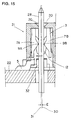
- Fig. 15 shows an enlarged section of the electric connector 21 with the extension 28 inserted therethrough/When the extension 28 of the pin type terminal 27 is inserted into the terminal 3 in the proper centered position (i.e. straight along the center line 30 between the contact beams 7A and 7B), the contact points 9A and 9B will contact the mating edge of the extension 28 with equal contact force to establish a uniform electrical connection. On the other hand, when the extension 28 is inserted along line 31 parallel to but offset a distance from the line 30 which is equal distance from contact points 9A and 9B in Fig. 15, the contact point 9A is depressed toward the left in Fig. 15 for accommodating the extension 28 while causing resilient deformation of the contact beam 7A.
- Such action of the contact point 9A exerts a force on the second connecting piece 12 via the first connecting piece 10A.
- This force is then transmitted to the contact beam 7B carrying the contact point 9B via the first connecting piece 10B to bias the contact beam 7B toward the left in Fig. 15.
- the contact point 9B which is carried by the contact beam 7B comes into contact with the mating edge of the extension 28.
- the second connecting piece 12 transmits the resilient force between the contact beams 7A and 7B, the resilient contact forces to be exerted on the contact points 9A and 9B are substantially unified to permit the contacts to be depressed onto the extension 28 with substantially equal resilient force.
- the contact beams 7A and 7B can be formed to be flexible enough to accommodate any magnitude of offset in insertion of the male terminal. Therefore, permanent deformation of the contact beams 7A and 7B can be successfully eliminated.
- the electric connector employing the electric connector female terminal according to the present invention assures good electric contact irrespective of the offset or angle of insertion of the male terminal, while substantially avoiding the possibility of causing permanent deformation of the contact beams which may result in permanent contact failure.
- the connecting piece employed in the electric connector terminal according to the present invention does not interfere with the insertion and removal of the male terminal.
- the overall height of the terminal can be maintained substantially equal to that of the conventional terminals despite the presence of the connecting piece.
- the contact points are located at a substantially intermediate position on the beams the lever formed by the contact beam and the first connecting piece has sufficient contact length to assure a consistent force and thereby a consistently good electrical connection.
Landscapes
- Coupling Device And Connection With Printed Circuit (AREA)
- Manufacturing Of Electrical Connectors (AREA)
Abstract
Description
- The present invention relates generally to a female terminal for an electric connector. More specifically, the invention relates to an improvement for a U-shaped connector terminal, in which a pair of contact beams are formed in the base portion and contact points on each contact beam are arranged in opposition to each other.
- As is well know, U-shaped electric connector terminals have been widely used in various fields. Such a connector terminal typically has a base portion, a pair of contact beams integrally formed with the base portion and extending therefrom, and is formed into generally U-shaped configuration. Normally, contact points which make electrical connection with a male terminal are formed at the free ends of the pair of contact beams so as to receive the male terminal completely through the female terminal, such as a pin type terminal. The contact points exert a predetermined magnitude of a uniform contact pressure for establishing electrical connection. Although the contact beams of this type of electric connector terminal are formed integrally with the base portion, their actions are independent of each other. In other words, since the contact beams are not mechanically connected to each other, they can act independently of each other. One typical example of this type of the electric connector terminal has been disclosed in Japanese Unexamined Patent Publication (Kokai) No. 3-77284.
- In the prior art of the type briefly discussed above, when the male terminal, such as pin type terminal is inserted in proper alignment spaced equally from each contact point, which is along the center line between the pair of contact beams, then each of the contact points exerts an appropriate contact pressure to establish good electrical connection.
- However, it is possible that the male terminal may be inserted slightly offset from the center line between the contact beams or at an angle. In such case, since the conventional U-shaped terminal has a pair of independently movable contact beams, the male terminal may contact only one contact point. This can cause degradation or failure of the electrical connection. Furthermore, it can cause permanent deformation of one of the contact beams to cause a failure of the electrical connection in the subsequent use.
- To solve the problem of improperly inserted male terminals, prior art terminals have both ends of the contact beams fixed to one another. Example of these are shown in US Patent No. 2,767,283 filed July 5, 1955 and US Patent No, 4,943,248 filed July 24, 1990. However, no prior art terminals had contact beams connected to each other by a resilient connecting piece and no such terminals were adapted to receive a male terminal which can pass completely therethrough without the connecting piece obstructing the passage.
- In order to overcome the above-noted defects inherent in the prior art, an object of the present invention is to provide a female terminal for an electric connector, which can assure steady contact with a male terminal irrespective of the position and angle of insertion of the male terminal and prevent the contact beams from being permanently deformed due to an offset insertion position or offset insertion angle of the male terminal while allowing the male terminal to pass completely therethrough.
- The subject electric connector terminal comprises a pair of contact beams with one end extending from a base defining a path completely through the female terminal for accommodating a male terminal, to which an electrical connection is to be established.
- A pair of contact points on each contact beam facing each other is adapted to make an electrical connection with the male terminal.
- A resilient connecting piece is integrally formed with the ends of each contact beam opposite the terminal base. The resilient connecting piece is positioned out of the insertion path of the male terminal so that it may pass completely through the female terminal.
- With the above-mentioned invention, even when the male terminal is inserted at a position offset from the center position either straight in or at an angle, both of the opposed contact points will contact the male terminal. The contact point first making contact with the male terminal will move the one contact beam. Movement of this beam will move the resilient connecting piece thereby also moving the other contact beam. Also, since the connecting piece is positioned out of the path of the male contact, insertion and removal of the male terminal will never be obstructed by the female terminal.
-
- Fig. 1 is plan view of a sheet blank punched into the desired configuration for fabricating the preferred embodiment of a U-shaped female terminal according to the present invention;
- Fig. 2 is a plan view of the U-shaped terminal after the bending process performed for the sheet blank of Fig. 1;
- Fig. 3 is a section taken along line 3 - 3 of Fig. 2;
- Fig. 4 is a section taken along line 4 - 4 of Fig. 3;
- Fig. 5 is a front elevation of the terminal of Fig. 2;
- Fig. 6 is an enlarged partial back elevation of the terminal of Fig. 2;
- Fig. 7 is a plan view of an electric connector employing the preferred embodiment of the U-shaped terminal;
- Fig. 8 is a front elevation of the electric connector of Fig. 7;
- Fig. 9 is a back elevation of the electric connector of Fig. 7;
- Fig. 10 is a left side elevation of the electric connector of Fig. 7;
- Fig. 11 is a section taken along line 11 - 11 of Fig. 7;
- Fig. 12 is a section taken along line 12 - 12 of Fig. 11;
- Fig. 13 is a section showing one example of engagement between the preferred embodiment of the U-shaped female terminal and a pin type male terminal;
- Fig. 14 is a section showing another example of engagement between the preferred embodiment of the U-shaped terminal and the pin type terminal; and
- Fig. 15 is an enlarged section showing contacting action of respective contacts of a pair of contact beams of the preferred embodiment of the U-shaped terminal and the
- pin type terminal.
- Referring now to the drawings, particularly to Figs. 1 to 6, construction of the preferred embodiment of an
electric connector terminal 3 according to the present invention will be discussed. Fig. 1 is a sheet blank which has been punched into a predetermined configuration adapted to fabricate theelectrical connector terminal 3. In the shown embodiment, the sheet blank is punched into a configuration adapted to be fabricated into a pair of terminals. However, it is not essential to fabricate the terminals in a pair. Any number can be punched including an individual terminal. Theterminals 3 are punched in a form connected to a carrier strip 1 via a connectingplate 2. Theterminal 3 has abase section 4. Asoldering tail 5 extends laterally from the side edge of the base section. Aleg 6 extends toward theconnecting plate 2 and is adjoined thereto. A pair ofcontact beams base portion 4 and extend therefrom. Thecontact beams gap 8 therebetween.Contact points contact beams contact points terminal 3 which extends through the lateral center of thegap 8 in parallel relationship with the longitudinal axis of thecontact beams contact points -
Terminal 3 further has a pair of first connecting pieces 10A and 10B extending substantially in alignment with thecontact beams piece 12 extends from the ends 11A and 11B of the first connecting pieces 10A and 10B. The second connectingpiece 12 is formed in an essentially U-shaped configuration. The U-shaped configuration of the connectingpiece 12 is intended to provide enough extra length for permitting thecontact points contact beams male terminal 27 therebetween, and to provide sufficient resilient return force for restoring the initial positions of thecontact points contact beams - The rounded bottom of the U-shaped connecting
piece 12 serves as a return spring which is stressed by the movement of the contact points 9A and 9B in directions to shift away from each other with accumulating resilient return force. This may be advantageous not only for providing resilient return force for the contact points 9A and 9B carried on thecontact beams male terminal 27 inserted therebetween. Once the force shifting the contact points 9A and 9B is released, thecontact piece 12 accumulating the resilient return force becomes active to return the contact points 9A and 9B carried on thecontact beams - It should be noted that the configuration of the
contact piece 12 is not specified to the U-shaped configuration but can be of any appropriate configuration to provide extra length for accommodating expansion of the distance between thecontacts contacts contact beams - The
terminal 3 is further formed with engagingpieces pieces housing 17 of the electric connector upon assembling theterminal 3 to the housing to complete the electric connector assembly. - In Fig. 1,
line 14, extending along the interface between thelegs 6 and the connectingplate 2, is a cutting line for cuttingrespective terminals 3 away from the carrier strip 1. In the preferred process of fabrication of the electric connector terminal, the bending process is performed before cutting theterminals 3 away from the carrier strip 1. In the bending process, thecontact beams line 15 to form a round and substantially U-shaped bend as best seen in Fig. 3. Bending is effected for thecontact beams line 15 in Fig. 1 in a direction out of the plane of the paper for forming a continuously curved bend without forming an angled edge. Further bending is effected at asecond bending line 16 shown in Fig. 1 in a manner best shown in Fig. 3. The order of bending at the respective first andsecond bending lines second bending line 16 in advance of effecting bending at thefirst bending line 15. - Figs. 2 to 6 show the
electric connector terminal 3 after the bending process. As set out above, after the bending process is complete, theterminal 3 is cut away from the carrier strip 1 at the cuttingline 14. - As can be seen from Fig. 4 which is the section taken along line 4 - 4 of Fig. 3, the substantially U-shaped second connecting
piece 12 is positioned behind thecontact beams pin type terminal 27. Therefore, connectingpiece 12 may not interfere with the insertion and removable of themale terminal 27. Furthermore, with the shown construction, the height of thecontact beams terminal 3 can be maintained compact enough so as not to require extra space for providing theconnection piece 12. - Figs. 7 to 12 show one example of an
electric connector 21 employing the preferred embodiment of theelectric connector terminal 3. Theelectric connector 21 includes an electricallyinsulative housing 17,boss sections 18 extending from both longitudinal ends of thehousing 17 for receiving fixing legs 91 which extend downwardly from the lower surface of thehousing 17 to engage positioning holes formed on a stationary member to mount theelectric connector 21. - The
housing 17 defines one or moreterminal receptacle cavities 33 for receiving therein theelectric connector terminals 3. As best shown in Fig. 11, theterminals 3 are disposed within each of the terminal receivingcavities 33 arranged in two rows respectively having a plurality of cavities in the longitudinal direction in parallel relationship to the longitudinal axis of thehousing 17. Once a terminal is fully inserted within theterminal receiving cavities 33, theterminal 3 engages the engagingpieces soldering tail 5 extends from theterminal 3 beyond the transverse edge of thehousing 17 so as to facilitate coupling with a trace on a printed circuit board. - The preferred embodiment of the electric connector terminal is designed for surface installation to a printed circuit board. However, the shown embodiment of the
electric connector terminal 3 is applicable to electric connectors having a variety of mounting means. Therefore, the shown embodiment of the electric connector is to be understood merely as an illustrative example of the preferred embodiment of theelectric connector terminal 3. - As can be seen from Fig. 11, the
terminal 3, disposed in the terminal receivingcavity 33, aligns the contact points 9A and 9B with aterminal receiving opening 20 defined through the top wall of thehousing 17. As shown in Fig. 12, the position of theterminal receiving opening 20 is laterally offset from the longitudinal axis position so that it may be aligned with the center axis of thegap 8 defined between the contact points 9A and 9B. At this position, theterminal 3 defines aclearance 32 below the contact points 9A and 9B to permit themale terminal 27 to extend completely therethrough. - Examples of how a
male connector 24 withmale pin terminals 27 are used to connect two printed circuit boards, are illustrated in Figs. 13 and 14. In the shown examples, themale connectors 24 havehousings 25 defining two rows of a plurality ofpin holding holes 26, to which themale pin terminals 27 are inserted and extended therefrom. In the construction shown in Figs. 13 and 14, each of thepin type terminals 27 has oneextension 28 extending from one end of thehousing 25 and theother extension 29 extending from the other end of the housing. One or both of theextensions pin type terminal 27 are inserted through theterminal receiving openings 20 of theelectric connector housing 17 to engage with the contact points 9A and 9B as shown in Figs. 13 and 14. - As set forth above, the preferred embodiment of the
electric connector 21 is designed for surface installation. Therefore, in the example of Fig. 13, twoelectric connectors 21 are installed on respective surfaces of printedcircuit boards extensions electric connector 3 respectively mounted on the printedcircuit boards circuit boards circuit boards extensions 29 of themale connectors 24 are inserted into through openings defined in the printedcircuit board 23 and directly secured thereto by soldering. In this case, theextension 29 is coupled with the circuit trace on the printed circuit board with direct contact or through the conductive soldering, and theelectric connector 24 is fixedly secured on the printedcircuit board 23. Theextensions 28 of theelectric connector 24 in Fig. 14 are inserted through theelectric connector terminals 3 of theelectric connector 21 mounted on the printedcircuit board 22 for establishing electrical connection between the printedcircuit boards - In the examples shown in both Figs. 13 and 14, the
extensions pin type terminals 27 are inserted through theterminal receiving clearances 32 of theterminals 3 and through thegaps 8 between the contact points 9A and 9B while the contacts shift away from each other to accommodate the associatedextensions contact beams pieces 10A, 10B and 12 with accumulating resilient returning force. The resilient returning force of the connectingpieces 10A, 10B and 12 cooperates with the reacting resilient force of thecontact beams contacts extensions pin type terminals 27 and thereby establish firm engagement for steady electric connection therebetween. The tip ends of theextensions terminal 3 and extend through thehousings 17 of theelectric connectors 21 through theterminal receiving openings 20. - Fig. 15 shows an enlarged section of the
electric connector 21 with theextension 28 inserted therethrough/When theextension 28 of thepin type terminal 27 is inserted into theterminal 3 in the proper centered position (i.e. straight along thecenter line 30 between thecontact beams extension 28 with equal contact force to establish a uniform electrical connection. On the other hand, when theextension 28 is inserted alongline 31 parallel to but offset a distance from theline 30 which is equal distance fromcontact points contact point 9A is depressed toward the left in Fig. 15 for accommodating theextension 28 while causing resilient deformation of thecontact beam 7A. Such action of thecontact point 9A exerts a force on the second connectingpiece 12 via the first connecting piece 10A. This force is then transmitted to thecontact beam 7B carrying thecontact point 9B via the first connecting piece 10B to bias thecontact beam 7B toward the left in Fig. 15. As a result, thecontact point 9B which is carried by thecontact beam 7B comes into contact with the mating edge of theextension 28. Since the second connectingpiece 12 transmits the resilient force between thecontact beams extension 28 with substantially equal resilient force. When theextension 28 is inserted in an angle relative to thecenter line 30 either at the right position or the offset position, a substantially similar effect of force transmission is performed by the connectingpiece 12 for assuring steady contact between the contact points 9A and 9B with theextension 28. - Since the return force to return the contact points 9A and 9B with the
contact beams piece 12, thecontact beams contact beams - As set forth above, the electric connector employing the electric connector female terminal according to the present invention, assures good electric contact irrespective of the offset or angle of insertion of the male terminal, while substantially avoiding the possibility of causing permanent deformation of the contact beams which may result in permanent contact failure. Furthermore, the connecting piece employed in the electric connector terminal according to the present invention does not interfere with the insertion and removal of the male terminal. Also, according to the present invention, the overall height of the terminal can be maintained substantially equal to that of the conventional terminals despite the presence of the connecting piece. In addition, since the contact points are located at a substantially intermediate position on the beams the lever formed by the contact beam and the first connecting piece has sufficient contact length to assure a consistent force and thereby a consistently good electrical connection.
- While the invention has been described with respect to a preferred embodiment, it is apparent that various changes can be made without departing from the scope of the invention as defined by the appended claims.
Claims (3)
- An electric connector female terminal (3) comprising:
a pair of contact beams (7A, 7B) each with one end extending from a base (4) defining a path (8) completely through said female terminal for accommodating a male terminal (27), to which an electrical connection is to be established;
a contact point (9A, 9B) on each contact beam facing each other adapted to make an electrical connection with said male terminal; and
a resilient connecting piece (12) integrally formed with an end (11A, 11B) of each contact beam opposite the base and extending therebetween, said connecting piece, positioned out of said path (8) for accommodating said male terminal adapted to resiliently bias the contact beams carrying the contact points to a predetermined initial position. - An electric connector terminal as set forth in claim 1, wherein said resilient connecting piece comprises a U-shaped bent portion (12).
- An electric connector terminal as set forth in claim 1, wherein said resilient connecting piece comprises a pair of substantially straight first segments (10A, 10B) respectively with each end extending substantially in alignment with and bent from said contact beams at which said contact points are carried, and a substantially U-shaped second segment (12) extending between the ends (11A, 11B) of the first segments (10A, 10B) opposite the bent ends.
Applications Claiming Priority (2)
| Application Number | Priority Date | Filing Date | Title |
|---|---|---|---|
| JP4080508A JPH07123058B2 (en) | 1992-03-02 | 1992-03-02 | Electrical connector terminal |
| JP80508/92 | 1992-03-02 |
Publications (2)
| Publication Number | Publication Date |
|---|---|
| EP0559057A1 true EP0559057A1 (en) | 1993-09-08 |
| EP0559057B1 EP0559057B1 (en) | 1996-12-04 |
Family
ID=13720261
Family Applications (1)
| Application Number | Title | Priority Date | Filing Date |
|---|---|---|---|
| EP93102824A Expired - Lifetime EP0559057B1 (en) | 1992-03-02 | 1993-02-24 | Electrical connector terminal |
Country Status (8)
| Country | Link |
|---|---|
| US (1) | US5306182A (en) |
| EP (1) | EP0559057B1 (en) |
| JP (1) | JPH07123058B2 (en) |
| KR (1) | KR970001612B1 (en) |
| DE (1) | DE69306280T2 (en) |
| ES (1) | ES2095506T3 (en) |
| FI (1) | FI930907A (en) |
| SG (1) | SG45299A1 (en) |
Cited By (3)
| Publication number | Priority date | Publication date | Assignee | Title |
|---|---|---|---|---|
| FR2766630A1 (en) * | 1997-07-25 | 1999-01-29 | Proner Comatel Sa | Female electrical connector with multiple contacts in insulating housing |
| WO2005088774A1 (en) * | 2004-03-09 | 2005-09-22 | 3M Innovative Properties Company | Deformable terminal and a strobe light unit that includes the terminal |
| WO2012025524A1 (en) * | 2010-08-25 | 2012-03-01 | Robert Bosch Gmbh | Contact element for making contact with a circuit carrier, and circuit carrier comprising a contact element |
Families Citing this family (15)
| Publication number | Priority date | Publication date | Assignee | Title |
|---|---|---|---|---|
| US5431576A (en) * | 1994-07-14 | 1995-07-11 | Elcon Products International | Electrical power connector |
| US5575691A (en) * | 1995-05-05 | 1996-11-19 | Elcon Products International | Apparatus for front or rear extraction of an electrical contact from a connector housing |
| US5807120A (en) * | 1996-03-06 | 1998-09-15 | Elcon Products International | Printed circuit board power distribution connector |
| USD412489S (en) * | 1998-04-16 | 1999-08-03 | Elcon Products International | Electrical connector housing |
| USD408361S (en) * | 1998-04-24 | 1999-04-20 | Elcon Products International Company | Electrical connector housing |
| USD420325S (en) * | 1998-04-24 | 2000-02-08 | Tvm Group, Inc. | Electrical connector |
| USD410894S (en) * | 1998-04-24 | 1999-06-15 | Elcon Products International Company | Electrical connector housing |
| US6299492B1 (en) | 1998-08-20 | 2001-10-09 | A. W. Industries, Incorporated | Electrical connectors |
| TW562308U (en) * | 2003-04-02 | 2003-11-11 | Hon Hai Prec Ind Co Ltd | Contact of electrical connector |
| JP5195230B2 (en) * | 2008-09-26 | 2013-05-08 | 住友電装株式会社 | Electric wire with terminal bracket |
| US8062055B2 (en) * | 2009-06-11 | 2011-11-22 | Tyco Electronics Corporation | Multi-position connector |
| JP5388350B2 (en) * | 2009-11-17 | 2014-01-15 | イリソ電子工業株式会社 | Electrical connection terminal and connector using the same |
| CN201741876U (en) * | 2010-03-31 | 2011-02-09 | 富士康(昆山)电脑接插件有限公司 | Electric coupler and conductive terminal thereof |
| JP2013149454A (en) * | 2012-01-19 | 2013-08-01 | Molex Inc | Terminal and connector |
| CN105794052B (en) * | 2013-11-27 | 2020-03-20 | 安费诺富加宜(亚洲)私人有限公司 | Electrical connector comprising a guide member |
Citations (7)
| Publication number | Priority date | Publication date | Assignee | Title |
|---|---|---|---|---|
| US2767283A (en) * | 1955-07-05 | 1956-10-16 | Gen Patent Corp | Cartridge fuse holder |
| FR2071910A5 (en) * | 1969-12-06 | 1971-09-17 | Schiffmann Gmbh Alois | |
| EP0135988A1 (en) * | 1983-08-04 | 1985-04-03 | AMP INCORPORATED (a New Jersey corporation) | Electrical connector having contacts which have receptacles that conform to inserted pin |
| DE3518067A1 (en) * | 1985-05-20 | 1986-11-20 | Siemens Ag | Contact spring |
| DE8535174U1 (en) * | 1985-12-13 | 1987-06-11 | Siemens Ag, 1000 Berlin Und 8000 Muenchen, De | |
| EP0349154A2 (en) * | 1988-06-29 | 1990-01-03 | Molex Incorporated | Electrical terminal and connector for bladed fuse |
| EP0463608A2 (en) * | 1990-06-27 | 1992-01-02 | Yazaki Corporation | Joint terminal |
Family Cites Families (9)
| Publication number | Priority date | Publication date | Assignee | Title |
|---|---|---|---|---|
| US3973919A (en) * | 1972-04-04 | 1976-08-10 | Hans Simon | Strip for springy contacts |
| US4118103A (en) * | 1977-09-15 | 1978-10-03 | Amp Incorporated | Double-ended connecting device |
| US4408824A (en) * | 1981-06-08 | 1983-10-11 | Amp Incorporated | Wire-in-slot terminal |
| JPS59110218A (en) * | 1982-12-15 | 1984-06-26 | Japan Radio Co Ltd | Generating circuit of multivalued impulse response waveform |
| US4943248A (en) * | 1988-06-29 | 1990-07-24 | Molex Incorporated | Electrical terminal for bladed fuse |
| US4907990A (en) * | 1988-10-07 | 1990-03-13 | Molex Incorporated | Elastically supported dual cantilever beam pin-receiving electrical contact |
| US4900271A (en) * | 1989-02-24 | 1990-02-13 | Molex Incorporated | Electrical connector for fuel injector and terminals therefor |
| DE4017815C2 (en) * | 1990-06-01 | 2001-09-20 | Cherry Mikroschalter Gmbh | Contact clamp for insulation displacement connections |
| US5046972A (en) * | 1990-07-11 | 1991-09-10 | Amp Incorporated | Low insertion force connector and contact |
-
1992
- 1992-03-02 JP JP4080508A patent/JPH07123058B2/en not_active Expired - Lifetime
-
1993
- 1993-02-24 ES ES93102824T patent/ES2095506T3/en not_active Expired - Lifetime
- 1993-02-24 DE DE69306280T patent/DE69306280T2/en not_active Expired - Fee Related
- 1993-02-24 EP EP93102824A patent/EP0559057B1/en not_active Expired - Lifetime
- 1993-02-24 SG SG1996003034A patent/SG45299A1/en unknown
- 1993-02-26 US US08/023,291 patent/US5306182A/en not_active Expired - Fee Related
- 1993-02-27 KR KR1019930002890A patent/KR970001612B1/en not_active IP Right Cessation
- 1993-03-01 FI FI930907A patent/FI930907A/en unknown
Patent Citations (7)
| Publication number | Priority date | Publication date | Assignee | Title |
|---|---|---|---|---|
| US2767283A (en) * | 1955-07-05 | 1956-10-16 | Gen Patent Corp | Cartridge fuse holder |
| FR2071910A5 (en) * | 1969-12-06 | 1971-09-17 | Schiffmann Gmbh Alois | |
| EP0135988A1 (en) * | 1983-08-04 | 1985-04-03 | AMP INCORPORATED (a New Jersey corporation) | Electrical connector having contacts which have receptacles that conform to inserted pin |
| DE3518067A1 (en) * | 1985-05-20 | 1986-11-20 | Siemens Ag | Contact spring |
| DE8535174U1 (en) * | 1985-12-13 | 1987-06-11 | Siemens Ag, 1000 Berlin Und 8000 Muenchen, De | |
| EP0349154A2 (en) * | 1988-06-29 | 1990-01-03 | Molex Incorporated | Electrical terminal and connector for bladed fuse |
| EP0463608A2 (en) * | 1990-06-27 | 1992-01-02 | Yazaki Corporation | Joint terminal |
Cited By (5)
| Publication number | Priority date | Publication date | Assignee | Title |
|---|---|---|---|---|
| FR2766630A1 (en) * | 1997-07-25 | 1999-01-29 | Proner Comatel Sa | Female electrical connector with multiple contacts in insulating housing |
| WO2005088774A1 (en) * | 2004-03-09 | 2005-09-22 | 3M Innovative Properties Company | Deformable terminal and a strobe light unit that includes the terminal |
| WO2012025524A1 (en) * | 2010-08-25 | 2012-03-01 | Robert Bosch Gmbh | Contact element for making contact with a circuit carrier, and circuit carrier comprising a contact element |
| CN103069650A (en) * | 2010-08-25 | 2013-04-24 | 罗伯特·博世有限公司 | Contact element for making contact with a circuit carrier, and circuit carrier comprising a contact element |
| CN103069650B (en) * | 2010-08-25 | 2016-05-18 | 罗伯特·博世有限公司 | Be used for the contact element of contact circuit carrier and the circuit carrier with contact element |
Also Published As
| Publication number | Publication date |
|---|---|
| ES2095506T3 (en) | 1997-02-16 |
| SG45299A1 (en) | 1998-01-16 |
| FI930907A (en) | 1993-09-03 |
| JPH05290912A (en) | 1993-11-05 |
| DE69306280D1 (en) | 1997-01-16 |
| US5306182A (en) | 1994-04-26 |
| EP0559057B1 (en) | 1996-12-04 |
| JPH07123058B2 (en) | 1995-12-25 |
| FI930907A0 (en) | 1993-03-01 |
| DE69306280T2 (en) | 1997-04-30 |
| KR930020776A (en) | 1993-10-20 |
| KR970001612B1 (en) | 1997-02-11 |
Similar Documents
| Publication | Publication Date | Title |
|---|---|---|
| US5306182A (en) | Electric connector terminal | |
| US6475040B1 (en) | Electrical contact receptacle to mate with round and rectangular pins | |
| US4907990A (en) | Elastically supported dual cantilever beam pin-receiving electrical contact | |
| US8092232B2 (en) | Board-to-board connector | |
| US7229298B2 (en) | Electrical connector having an improved grounding path | |
| US5533908A (en) | Latch and mounting member for a surface mounted electrical connector | |
| JP4425058B2 (en) | Contact structure and electrical connector using the same | |
| US4880401A (en) | Electric female connector piece | |
| EP0724313A2 (en) | Printed circuit board mounted electrical connector | |
| US7115005B2 (en) | Electrical connector having resilient contacts | |
| US4708416A (en) | Electrical connecting terminal for a connector | |
| EP0717468A2 (en) | Make-first-break-last ground connections | |
| EP0068656B1 (en) | Electrical terminal with cavity compensator | |
| KR100224055B1 (en) | Small pitch electrical connector | |
| JP2018092780A (en) | Connector device with come-off prevention structure | |
| JP4091702B2 (en) | Error absorbing connector | |
| GB2342789A (en) | Contact assembly for pcb interconnector | |
| CN114389108A (en) | Electrical connector with flat conductors | |
| JP7438076B2 (en) | Mating electrical connector and electrical connector assembly | |
| JPH11339906A (en) | Substrate mount connector | |
| CN114389107A (en) | Electric connector with flat conductor and electric connector assembly | |
| CN114514657A (en) | Connector and connector assembly | |
| JPH09106845A (en) | Electric contact | |
| JPH10116658A (en) | Connector for substrate | |
| JP2774394B2 (en) | Receptacle connector using flexible wiring board |
Legal Events
| Date | Code | Title | Description |
|---|---|---|---|
| PUAI | Public reference made under article 153(3) epc to a published international application that has entered the european phase |
Free format text: ORIGINAL CODE: 0009012 |
|
| AK | Designated contracting states |
Kind code of ref document: A1 Designated state(s): DE ES FR GB IT NL |
|
| 17P | Request for examination filed |
Effective date: 19940118 |
|
| 17Q | First examination report despatched |
Effective date: 19950519 |
|
| GRAG | Despatch of communication of intention to grant |
Free format text: ORIGINAL CODE: EPIDOS AGRA |
|
| GRAH | Despatch of communication of intention to grant a patent |
Free format text: ORIGINAL CODE: EPIDOS IGRA |
|
| ITF | It: translation for a ep patent filed |
Owner name: DE DOMINICIS & MAYER S.R.L. |
|
| GRAH | Despatch of communication of intention to grant a patent |
Free format text: ORIGINAL CODE: EPIDOS IGRA |
|
| GRAA | (expected) grant |
Free format text: ORIGINAL CODE: 0009210 |
|
| AK | Designated contracting states |
Kind code of ref document: B1 Designated state(s): DE ES FR GB IT NL |
|
| ET | Fr: translation filed | ||
| REF | Corresponds to: |
Ref document number: 69306280 Country of ref document: DE Date of ref document: 19970116 |
|
| REG | Reference to a national code |
Ref country code: ES Ref legal event code: FG2A Ref document number: 2095506 Country of ref document: ES Kind code of ref document: T3 |
|
| PLBE | No opposition filed within time limit |
Free format text: ORIGINAL CODE: 0009261 |
|
| STAA | Information on the status of an ep patent application or granted ep patent |
Free format text: STATUS: NO OPPOSITION FILED WITHIN TIME LIMIT |
|
| 26N | No opposition filed | ||
| PGFP | Annual fee paid to national office [announced via postgrant information from national office to epo] |
Ref country code: NL Payment date: 19981222 Year of fee payment: 7 |
|
| PGFP | Annual fee paid to national office [announced via postgrant information from national office to epo] |
Ref country code: GB Payment date: 19990108 Year of fee payment: 7 |
|
| PGFP | Annual fee paid to national office [announced via postgrant information from national office to epo] |
Ref country code: FR Payment date: 19990204 Year of fee payment: 7 |
|
| PGFP | Annual fee paid to national office [announced via postgrant information from national office to epo] |
Ref country code: ES Payment date: 19990219 Year of fee payment: 7 |
|
| PGFP | Annual fee paid to national office [announced via postgrant information from national office to epo] |
Ref country code: DE Payment date: 19990226 Year of fee payment: 7 |
|
| PG25 | Lapsed in a contracting state [announced via postgrant information from national office to epo] |
Ref country code: GB Free format text: LAPSE BECAUSE OF NON-PAYMENT OF DUE FEES Effective date: 20000224 |
|
| PG25 | Lapsed in a contracting state [announced via postgrant information from national office to epo] |
Ref country code: ES Free format text: LAPSE BECAUSE OF NON-PAYMENT OF DUE FEES Effective date: 20000225 |
|
| PG25 | Lapsed in a contracting state [announced via postgrant information from national office to epo] |
Ref country code: NL Free format text: LAPSE BECAUSE OF NON-PAYMENT OF DUE FEES Effective date: 20000901 |
|
| GBPC | Gb: european patent ceased through non-payment of renewal fee |
Effective date: 20000224 |
|
| PG25 | Lapsed in a contracting state [announced via postgrant information from national office to epo] |
Ref country code: FR Free format text: LAPSE BECAUSE OF NON-PAYMENT OF DUE FEES Effective date: 20001031 |
|
| NLV4 | Nl: lapsed or anulled due to non-payment of the annual fee |
Effective date: 20000901 |
|
| PG25 | Lapsed in a contracting state [announced via postgrant information from national office to epo] |
Ref country code: DE Free format text: LAPSE BECAUSE OF NON-PAYMENT OF DUE FEES Effective date: 20001201 |
|
| REG | Reference to a national code |
Ref country code: FR Ref legal event code: ST |
|
| REG | Reference to a national code |
Ref country code: ES Ref legal event code: FD2A Effective date: 20010910 |
|
| PG25 | Lapsed in a contracting state [announced via postgrant information from national office to epo] |
Ref country code: IT Free format text: LAPSE BECAUSE OF NON-PAYMENT OF DUE FEES Effective date: 20050224 |