EP0717468A2 - Make-first-break-last ground connections - Google Patents
Make-first-break-last ground connections Download PDFInfo
- Publication number
- EP0717468A2 EP0717468A2 EP95308237A EP95308237A EP0717468A2 EP 0717468 A2 EP0717468 A2 EP 0717468A2 EP 95308237 A EP95308237 A EP 95308237A EP 95308237 A EP95308237 A EP 95308237A EP 0717468 A2 EP0717468 A2 EP 0717468A2
- Authority
- EP
- European Patent Office
- Prior art keywords
- contact
- blade
- contacts
- housing
- receptacle
- Prior art date
- Legal status (The legal status is an assumption and is not a legal conclusion. Google has not performed a legal analysis and makes no representation as to the accuracy of the status listed.)
- Granted
Links
Images


Classifications
-
- H—ELECTRICITY
- H01—ELECTRIC ELEMENTS
- H01R—ELECTRICALLY-CONDUCTIVE CONNECTIONS; STRUCTURAL ASSOCIATIONS OF A PLURALITY OF MUTUALLY-INSULATED ELECTRICAL CONNECTING ELEMENTS; COUPLING DEVICES; CURRENT COLLECTORS
- H01R13/00—Details of coupling devices of the kinds covered by groups H01R12/70 or H01R24/00 - H01R33/00
- H01R13/648—Protective earth or shield arrangements on coupling devices, e.g. anti-static shielding
-
- H—ELECTRICITY
- H01—ELECTRIC ELEMENTS
- H01R—ELECTRICALLY-CONDUCTIVE CONNECTIONS; STRUCTURAL ASSOCIATIONS OF A PLURALITY OF MUTUALLY-INSULATED ELECTRICAL CONNECTING ELEMENTS; COUPLING DEVICES; CURRENT COLLECTORS
- H01R12/00—Structural associations of a plurality of mutually-insulated electrical connecting elements, specially adapted for printed circuits, e.g. printed circuit boards [PCB], flat or ribbon cables, or like generally planar structures, e.g. terminal strips, terminal blocks; Coupling devices specially adapted for printed circuits, flat or ribbon cables, or like generally planar structures; Terminals specially adapted for contact with, or insertion into, printed circuits, flat or ribbon cables, or like generally planar structures
- H01R12/70—Coupling devices
- H01R12/71—Coupling devices for rigid printing circuits or like structures
- H01R12/72—Coupling devices for rigid printing circuits or like structures coupling with the edge of the rigid printed circuits or like structures
- H01R12/722—Coupling devices for rigid printing circuits or like structures coupling with the edge of the rigid printed circuits or like structures coupling devices mounted on the edge of the printed circuits
- H01R12/724—Coupling devices for rigid printing circuits or like structures coupling with the edge of the rigid printed circuits or like structures coupling devices mounted on the edge of the printed circuits containing contact members forming a right angle
-
- H—ELECTRICITY
- H01—ELECTRIC ELEMENTS
- H01R—ELECTRICALLY-CONDUCTIVE CONNECTIONS; STRUCTURAL ASSOCIATIONS OF A PLURALITY OF MUTUALLY-INSULATED ELECTRICAL CONNECTING ELEMENTS; COUPLING DEVICES; CURRENT COLLECTORS
- H01R13/00—Details of coupling devices of the kinds covered by groups H01R12/70 or H01R24/00 - H01R33/00
- H01R13/648—Protective earth or shield arrangements on coupling devices, e.g. anti-static shielding
- H01R13/652—Protective earth or shield arrangements on coupling devices, e.g. anti-static shielding with earth pin, blade or socket
-
- H—ELECTRICITY
- H01—ELECTRIC ELEMENTS
- H01R—ELECTRICALLY-CONDUCTIVE CONNECTIONS; STRUCTURAL ASSOCIATIONS OF A PLURALITY OF MUTUALLY-INSULATED ELECTRICAL CONNECTING ELEMENTS; COUPLING DEVICES; CURRENT COLLECTORS
- H01R13/00—Details of coupling devices of the kinds covered by groups H01R12/70 or H01R24/00 - H01R33/00
- H01R13/648—Protective earth or shield arrangements on coupling devices, e.g. anti-static shielding
- H01R13/658—High frequency shielding arrangements, e.g. against EMI [Electro-Magnetic Interference] or EMP [Electro-Magnetic Pulse]
- H01R13/6581—Shield structure
- H01R13/6585—Shielding material individually surrounding or interposed between mutually spaced contacts
-
- H—ELECTRICITY
- H01—ELECTRIC ELEMENTS
- H01R—ELECTRICALLY-CONDUCTIVE CONNECTIONS; STRUCTURAL ASSOCIATIONS OF A PLURALITY OF MUTUALLY-INSULATED ELECTRICAL CONNECTING ELEMENTS; COUPLING DEVICES; CURRENT COLLECTORS
- H01R12/00—Structural associations of a plurality of mutually-insulated electrical connecting elements, specially adapted for printed circuits, e.g. printed circuit boards [PCB], flat or ribbon cables, or like generally planar structures, e.g. terminal strips, terminal blocks; Coupling devices specially adapted for printed circuits, flat or ribbon cables, or like generally planar structures; Terminals specially adapted for contact with, or insertion into, printed circuits, flat or ribbon cables, or like generally planar structures
- H01R12/50—Fixed connections
- H01R12/51—Fixed connections for rigid printed circuits or like structures
- H01R12/55—Fixed connections for rigid printed circuits or like structures characterised by the terminals
- H01R12/58—Fixed connections for rigid printed circuits or like structures characterised by the terminals terminals for insertion into holes
- H01R12/585—Terminals having a press fit or a compliant portion and a shank passing through a hole in the printed circuit board
-
- H—ELECTRICITY
- H01—ELECTRIC ELEMENTS
- H01R—ELECTRICALLY-CONDUCTIVE CONNECTIONS; STRUCTURAL ASSOCIATIONS OF A PLURALITY OF MUTUALLY-INSULATED ELECTRICAL CONNECTING ELEMENTS; COUPLING DEVICES; CURRENT COLLECTORS
- H01R13/00—Details of coupling devices of the kinds covered by groups H01R12/70 or H01R24/00 - H01R33/00
- H01R13/02—Contact members
- H01R13/10—Sockets for co-operation with pins or blades
- H01R13/11—Resilient sockets
- H01R13/113—Resilient sockets co-operating with pins or blades having a rectangular transverse section
-
- H—ELECTRICITY
- H01—ELECTRIC ELEMENTS
- H01R—ELECTRICALLY-CONDUCTIVE CONNECTIONS; STRUCTURAL ASSOCIATIONS OF A PLURALITY OF MUTUALLY-INSULATED ELECTRICAL CONNECTING ELEMENTS; COUPLING DEVICES; CURRENT COLLECTORS
- H01R13/00—Details of coupling devices of the kinds covered by groups H01R12/70 or H01R24/00 - H01R33/00
- H01R13/40—Securing contact members in or to a base or case; Insulating of contact members
- H01R13/405—Securing in non-demountable manner, e.g. moulding, riveting
- H01R13/41—Securing in non-demountable manner, e.g. moulding, riveting by frictional grip in grommet, panel or base
Definitions
- This invention relates generally to make-first-break-last ground connections and relates in particular to a pair of mating ground contacts for this purpose, an electrical connector assembly and an electrical blade contact.
- the invention is further directed to contacts having features for securely positioning the contacts within a housing passageway and to contacts that are self-polarizing.
- an electrical connector assembly comprising mating electrical connectors and having a power or signal circuit and a ground circuit
- the ground circuit should be made before the power or signal circuit when the connectors are mated and that when the connectors are unmated the power or signal circuit should be broken before the ground circuit.
- U.S. Patent No. 5,116,230 teaches that a make-first-break-last facility may be provided by making ground pins of a pin header longer than signal pins of the header so that the ground pins engage ground contacts of a mating connector, before the signal pins engage signal contacts thereof.
- French Patent No. 1,374,648 discloses a receptacle contact for receiving a contact blade.
- the receptacle contact comprises a rearward base from which extend forwardly, first and second contact springs having bowed the contact surfaces for engaging opposite faces of the blade.
- the first contact spring is in the form of a cantilever arm, the second contact spring comprising a pair of spring arms extending from the base, one on either side of the first contact spring.
- the spring arms of the second contact spring are connected at their ends by a strap.
- the contact surfaces of the second contact spring are formed on the spring arms thereof and so are divided by a slot defined by the spring arms of the second contact spring.
- the slot is substantially narrower than the contact blade throughout its length.
- Right angle electrical connectors are often used in the electronic industry to connect daughter cards to mother boards or the like.
- the daughter card connectors are mounted along the edge of a board such that the mating portion of the connector housing extends outwardly from and also partially below the board. This arrangement is often used when components are to be added to both sides of the daughter card.
- Some of the electrical connectors or modules used in such interconnections may carry power and/or signal circuits and a ground circuit. Power and ground circuits in particular may be carried by flat blade like contacts, which are stamped from strips of metal.
- the power as well as signal contacts used in the connectors be ones that can be press-fit into through-holes of a board thereby avoiding the extra steps needed for soldering the connections.
- the power contact connector or module be one that provides a plurality of current paths to the mating interface as well as to the traces on the circuit board.
- Polarization features can include for example, molding asymmetrical posts on the bottom of a connector housing, inserting one or more specialized contacts at selected locations in a connector housing or using a separate metal or plastic member disposed in the housing.
- An object of the invention is to provide improved economy in the manufacture of electrical ground contacts for a make-first-break-last grounding connection in the electrical connector assembly having ground and power or signal contacts.
- a pair of mating electrical ground contacts comprises a blade contact having a rearward blade support for retention in a first insulating housing, a contact blade projecting forwardly from the blade support and a tab which is substantially narrower than the contact blade projecting forwardly from a forward edge of the contact blade.
- the pair of ground contacts further comprises a receptacle contact having a rearward base for retention in a second insulating housing, and first and second contact springs projecting forwardly from the base.
- the first contact spring has a first transverse contact surface, the second contact spring having a transverse contact surface which is substantially wider than the tab.
- the contact surfaces of the contact springs cooperate to apply contact forces initially to the tab and then to the contact blade as the ground contacts are being mated.
- the second contact spring defines a rearward opening for receiving the tab.
- the contact blade of the blade contact need not, where the ground contacts are used in a make-first-break-last connector assembly, be any longer than, and is preferably of the same length as, power or signal contact blades of the assembly. Since the tab is substantially narrower than the contact blade of the ground blade contact, there is afforded economy of metal in the manufacture of the ground blade contact. At the same time, where the contact blades of the power or signal blade contacts, are of the same effective length as the ground contact blade of the ground blade contact, all of the contact blades can engage their receptacles substantially simultaneously in order to handle the full current load.
- the first contact spring of the receptacle contact is substantially narrower than the contact surface of the second contact spring
- the first contact spring can, in manufacture, be economically struck out from the stock which is used to form the second contact spring, at the same time leaving the second contact spring with a wide and continuous contact surface supported from the base of the receptacle contact by a pair of spring arms one on each side of the first contact spring and providing said rearward opening for receiving the tab.
- all the contacts of the connector assembly can conveniently be identical excepting that the contact blade of the ground blade contact is provided with the tab, whereas the remaining contact blades are not.
- one of the other contact blades also may be provided with a tab that is shorter in length than the tab on the ground blade contact, thereby establishing a make-first, make-second, and a make-last arrangement.
- an electrical connector assembly comprises mating electrical connectors having a ground blade contact for mating with a ground receptacle contact and current transmitting blade contacts, that is to say power or signal contacts, for mating with respective current transmitting receptacle contacts.
- the ground blade contact has a contact blade with a projecting tab which is narrower than the contact blade, for engaging with the ground receptacle contact before the contact blade engages with the ground receptacle contact.
- Each current transmitting blade contact has a contact blade for engaging with the respective current transmitting receptacle contact as the contact blade of the ground blade contact engages with the ground receptacle contact which has an opening for receiving the tab as the contact blades are being mated with the receptacle contacts.
- the connector assembly can thus handle a full current load.
- each contact blade may be formed, according to another aspect of the invention, with elongate, parallel raised areas extending towards the forward edge of the contact blade and terminating back therefrom.
- the raised areas project in opposite directions from the plane of the contact blade for engaging opposed contact surfaces of the mating receptacle contact as the contact blade is inserted therebetween.
- the thickness of the metal stock from which the blade contact is made need not be determined by the extent of the minimum gap between the contact surfaces of the receptacle contact, which is dictated in practice by forming and plating requirements. Also, the elongate raised areas serve to wipe any fouling, or metal oxide which may be present on the contact surfaces.
- the present invention is directed to a right angle electrical connector having a housing with a mating face adapted to mate with a complementary connector, an assembly face adapted to receive at least one electrical contact therein and a third face adapted for establishing electrical connection with a circuit board or complementary electrical article; and an electrical contact disposed in a contact-receiving passageway and having a first connecting portion exposed to the mating face for electrical engagement with the complementary connector and a second connecting portion extending from the third face of the housing and outwardly therefrom for electrical connection to the electrical article.
- the assembly face of the housing is opposed from the mating face thereof and the third face is at right angles to the mating face.
- the contact-receiving passageway further includes a contact-receiving slot open to the third face and to the assembly face.
- the second connecting portion of the contact is at right angles to the first connecting portion.
- the contact also includes a retention section remote from and opposite to the second connecting portion and associated with a cooperable housing portion.
- the cooperable housing portion is opposite from the third face and defines a channel extending forwardly from the assembly face toward the mating face.
- the channel is adapted to receive the contact retention section thereinto when the contact is received in the assembly face of the housing.
- the contact retention section includes a barb at the leading end thereof receivable in the forward portion of the channel and is dimensioned to create an interference fit such that the contact resists rearward movement after full assembly into the housing.
- the contact retention section further includes an outwardly extending lance or alternatively an embossment, which is received in a cooperable portion of the housing channel to stabilize the contact against the opposite side wall of the passageway thereby stabilizing the contact in the housing.
- the body of the contact includes an embossment which extends outwardly from the surface of the intermediate contact body in the same direction as lance. The embossment assures that the contact body is positioned in the contact-receiving passageway against the sidewall proximate the mating face end of the passageway. By holding the contact securely against the sidewall of the contact-receiving passageway, alignment of the first connecting portion of the contact at the mating face is assured. Furthermore, the use of an embossment on the body allows the width of the passageway to be greater than the thickness of the contact thereby permitting the first connecting portion to move freely through the passageway thus avoiding damage to any plating thereon.
- An advantage of the present invention is that it facilitates manufacturing and assembly of the connectors by providing a power or ground contact that is can be press-fit into through-holes of a board thereby avoiding the need to solder the terminal leads.
- the contacts and connector of the present invention further provide a plurality of contact paths to the mating interface and to the circuit board traces.
- the connector assembly of the present invention in addition allows the mating blade to overhang the circuit board while securely positioning the contact in the housing.
- the present invention is also directed to an electrical contact that is self-polarizing.
- the electrical contact includes a body portion having first and second connection sections at opposite ends thereof and at least three legs extending from a common end of the body portion all together comprising one of the first and second connecting sections of the contact.
- the first of the at least three legs is spaced from the second leg a selected first distance and the second leg is spaced from the third leg a selected second distance, the first distance being different from the second.
- the at least three legs are adapted to be received in respective through-holes of a circuit board in a polarized arrangement.
- the invention is further directed to a connector assembly including a housing having at least one electrical contact disposed therein that includes the polarized arrangement defined above.
- the housing may further include additional self-polarizing contacts or a variety of other contacts.
- the self-polarizing electrical contact is particularly suitable for use with power and ground contacts which typically have a plurality of contact tails.
- the contact of the present invention further is cost effective to manufacture and eliminates the need for other polarizing features for a connector to be mounted to a circuit board.
- An electrical connector assembly in the form of an electrical power module 2 comprises a blade connector 4 and a receptacle connector 6.
- the blade connector 4 comprises an insulating housing 8 having a body 10 and a shroud 12 projecting forwardly from a mating face 14 of the body 10.
- the body 10 defines a central, contact receiving cavity 16.
- the body 10 has two outer, contact receiving cavities 17, which are indicated in broken lines in Figure 1, one cavity 17 being disposed on each side of the cavity 16. Since the cavities 16 and 17 are identical, only the cavity 16 will be described here.
- the cavity 16 has a rearward, contact receiving, open side 18 and a laterally open side 20 adjacent thereto.
- the body 10 has an end wall 22 opposite to the open side 20 and opposite side walls 24 adjacent to the side 20.
- the cavity 16 has opposite side walls 25, only one of which is shown ( Figures 7 and 8). There projects rearwardly, from a forward rudimentary wall 27 of the body 10, rearwardly into the cavity 16, a contact retention rib 26. As shown in Figures 7 and 8, the shroud 12 projects rightwardly (as seen in Figures 7 and 8), beyond the open side 20 of the cavity 16 to define, in cooperation with the body 10, a recess 29.
- Each cavity 16 and 17 opens forwardly into an internal cavity 28 of the shroud 12.
- the shroud 12 has opposite side walls 30 and opposite side walls 32, having respective guide chamfers 34 and 36 at their forward ends.
- a substantially uniplanar ground blade contact 38 which is best seen in Figure 5, is secured in the central cavity 16.
- the blade contact 38 best seen in Figure 5, comprises a rearward blade support plate 40 and a forwardly projecting contact blade 42 connected to the blade 40 by a transition neck 44.
- the plate 40 has a rectilinear rear edge 46, from which extends at right angles thereto, a lateral edge 48. There extend normally, from a lateral edge 50 of the plate 40, opposite to the edge 48, compliant contact tails 52.
- the plate 40 has a latching tongue 54 proximate to the edge 48 and the transition neck 44 has a retention boss 56 projecting in the same direction as the tongue 54.
- the contact blade 42 has a tab 64 projecting forwardly from the forward edge 66 of the blade 42.
- the width of the tab 64 is approximately one third of the overall width of the blade 42.
- the ground blade contact 38 was inserted through the open side 18 of the cavity 16 with the tab 64 leading, so that the boss 56 pressed against the proximate side wall 25, the latching tongue 54 engaging a shoulder (not shown) of the side wall 25 and the barb 62 biting into the retention rib 26, the blade contact 38 being thereby secured in the cavity 16 with the contact tails 52 projecting from the open side 20 of the cavity 16 into the recess 29 and the contact blade 42 projecting forwardly into a cavity 28 of the shroud 12.
- the connector 4 further comprises a pair of power blade contacts 68, one of which is shown in Figure 6. Those parts of the contact 68 which are identical with corresponding parts of the contact 38 bear the same reference numerals as in the contact 38.
- Each contact 68 differs from the contact 38 in that the contact blade 70 of the contact 68 is devoid of the tab 64, having a rectilinear forward edge 71.
- Each power blade contact 68 is retained in a respective one of the cavities 17 in the same manner and in the same orientation as the ground blade contact 38 is retained and oriented in its cavity 16.
- the contact blades 70 project forwardly into the cavity 28 of the shroud 12 and the contact tails 52 of each contact 68 project from the housing body 10 in parallel relationship with the contact tails of the ground contact 38.
- the connector 4 is mounted to the edge of a first circuit board CB1 such that board CB 1 is positioned in the recess 29 with the contact tails 52 of the ground contact 38 extending through plated holes in the board CB1 and electrically connected to a ground conductor or ground conductors (not shown) thereon by means of a compliant portion, solder or other means as known in the art.
- the contact tails 52 of the power contacts 68 extending through further plated through holes in the board CB1 and electrically connected to power conductors thereon.
- the receptacle connector 6 comprises an insulating housing 72 for mating reception to the shroud 12 of the connector 4.
- the housing 72 has a mating face 74, a contact receiving face 76 opposite thereto, opposite side walls 78 and opposite end walls 80.
- the housing 72 defines a central contact receiving cavity 82 and a lateral contact receiving cavity 84 on each side thereof.
- Each cavity 82 and 84 opens at its forward end into a contact blade guide slot 86 in the mating face 74, and opens at its rear end into the contact receiving face 76.
- the central cavity 82 is separated from cavities 84 by partitions 88.
- each end wall 80 has a vertical slot 98 extending between the faces 74 and 76 and a chamfered outer edge 100 proximate to the face 76.
- each contact 96 comprises a rearward elongate base 102 having at each end thereof a retention boss 104. There depend from the rear edge of the base 102 compliant contact tails 106 identical with the contact tails 52 of the contacts 38 and 68. There upstands from the forward edge of the base 102, a contact spring 108 having an inwardly bowed, smoothly arcuate, transverse contact surface 110 surmounting a forwardly extending spring arm 112.
- the contact surface 110 is of substantially the same width as the tab 64.
- a further contact spring 114 comprises a pair of spring arms 116 each extending from the forward edge of the base 102, on opposite sides of the contact spring 108 and being joined at their forward ends by a strap 118 having an inwardly bowed, smoothly arcuate, transverse contact surface 120, spaced slightly forwardly of the contact surface 110.
- the contact surface 120 is of substantially the same width as the contact blade 42.
- Each spring arm 116 has a bent portion 122 proximate to the base 102 laterally offsetting the arm 116 from the contact spring 108, whereby an opening 124 is provided near the base 102, between the contact springs 108 and 114.
- Contact springs 108 and 114 converge slightly in the forward direction.
- Each contact 96 is inserted into its cavity in the housing 72 by way of the contact receiving face 76, with the end portions of the base 102 received in the rear end portions of the slots 98, and the bosses 104 engaged against the slot walls.
- the contact 96 is thereby temporarily retained in position in their cavities while the contact tails 106 are inserted through plated through holes in a second circuit board CB2 and are electrically connected to respective conductors (not shown) thereon.
- the contact tails of the receptacle contact in the cavity 82 are electrically connected to a ground conductor or ground conductors on the board CB2, while the contact tails of the contacts 92 in the cavities 84 are electrically connected to respective power conductors in the board CB2.
- each blade 42 and 70 is aligned with contact surfaces 110 and 120 of a respective receptacle contact 96.
- the forward edge 71 of each blade 70 then enters the guide slot 86 of a respective cavity 84 and the forward edge 66 of the blade 42 enters the guide slot 86 of the cavity 82.
- the tab 64 which projects forwardly from the edge 66 of the blade 62 engages between both of the contact surfaces 110 and 120 of the ground receptacle contact 96 in the central cavity 82 of the housing 72.
- the ground circuit of the power module 2 is therefore made before the power circuit thereof, since the blades 70 are, at this time, spaced from the power contacts 96.
- each of the blades 42 and 70 passes between the contact surfaces 110 and 120 of a respective contact 96, whereby the power circuit of the module 2 is also made.
- the tab 64 then lies between spring arms 112 and 116 of the ground contact 96 in the cavity 82.
- the connector 4 is retracted between the positions of Figures 4, 3, 2 and 1 respectively.
- the blade 42 by way of its tab 64, enters between the contact surfaces 110 and 120 of the contact 96 in the cavity 82 after the blades 70 have been retracted from the contacts 96 in the cavities 84.
- the ground circuit of the module 2 remains made, until after the power circuit of the module has been broken.
- the contact blades disengage from their receptacle contacts substantially simultaneously the power module no longer has its full current load.
- the spring arms 112 and 116 of the contacts 96 are cammed resiliently apart as shown in Figures 2 and 3.
- the blade insertion forces are, however, reduced because the contact surfaces 110 and 120 are offset from each other in the mating direction.
- the contacts in the cavities 84 need not be identical with the contact 96 in the cavity 82, but may be conventional contacts of the tulip type, for example. In the interest of manufacturing, inventory keeping, and convenience, however, all of the receptacle contacts are preferably identical.
- the connectors 4 and 6 may have a greater number of power and ground contacts and in other arrangements than those described above, and furthermore may be used other than as a power module, the current transmitting contacts being signal contacts instead of power contacts, for example.
- the contacts 38, 68 and 96 are stamped from sheet metal stock by means of progressive die stamping and forming operations and at least their contact surfaces will usually be plated, for example, with gold or tin, in accordance with the field of use of the contacts.
- the contact springs 108 and 114 must be spaced by a certain minimum gap in the interest of forming and plating requirements.
- the blade must be of a maximum thickness which is compatible with said gap. Nevertheless, in the interest of economy of metal, the thickness of the metal stock from which the blade contacts are stamped, is preferably less than said maximum thickness.
- a blade contact 38' shown in Figures 9 to 14 differs from the blade contact 38, described above, in that the part of the blade 42' which passes between the contact surfaces 110 and 120 of the receptacle contact 96 is formed with elongate, laterally aligned raised areas 140, 142 and 144 which extend longitudinally of the blade 42' all to the same extent, and which are evenly spaced laterally of the blade 42'. Each raised area terminates back from the forward edge 66 of the contact blade 42'.
- the raised areas 140 and 144 project from the plane of the blade 42' in the opposite sense to the raised area 142 which is located between the areas 140 and 144.
- Figures 9 and 12 show the receptacle contact 96 before the tab 64 is inserted between the contact springs 108 and 114, with the contact surfaces 110 and 120 thereof defining said minimum gap.
- Figures 10 and 13 show the tab 64 inserted between the contact surfaces 110 and 120, the contact springs 108 and 114 being thereby resiliently deflected to produce a moderate normal contact force between the tab 64 and the contact surfaces 110 and 120.
- the raised areas 140, 142 and 144 engage the contact surfaces 110 and 120 to produce a greater resilient deflection of the contact springs 108 and 114 thereby providing a substantially higher normal contact force between the tab 64' and the contact surfaces 110 and 120.
- the raised areas 140 and 144 wipe the contact surface 120 near the ends of the strap, in line with spring beams 114. and the raised area 142 wipes the contact surface 110.
- the raised areas 140, 142 and 144 are sufficiently elongate in the mating direction to provide effective wiping of the contact surfaces 110 and 120 to remove any fouling or metal oxide, as the case may be, from the contact surfaces. Similar raised areas are preferably also provided on the contact blades 70 of the blade contacts 68.
- the blade contact 38' also differs from the blade contact 38 in that its support plate 40 is formed with a retention rib 146 instead of with the latching tongue 54.
- Figure 15 illustrates an arrangement of blade connectors 4 and signal receptacles 5 mounted to daughter board CB3 and a complementary arrangement of receptacle connectors 6 and headers 7 mounted to mother board CB4.
- the arrangements also show guide modules 90,92, which aid in aligning the modules as the respective connectors 4,5 on daughter board CB3 are mated with the complementary connectors 6,7 on mother board CB4.
- Figure 15 also illustrates that housing 8 of blade connector 4 extends beyond the housing 9 of receptacles 5 and that the housing 72 of connector 6 is shorter that housing 73 of header 7.
- the leading edge of housing 8 is beveled at 34 to minimize stubbing of housing 8 with the corner 75 of housing 73 as the respective connectors are mated.
- each connector could be provided with both blade contacts and receptacle contacts.
- the housing 8 has a mating face 14 adapted to mate with a complementary electrical connector such as connector 6 shown in Figure 23, an assembly face 15 adapted to receive at least one electrical contact 38 therein and a third face 23 adapted for establishing electrical connection with a complementary electrical article such as circuit board 90 shown in Figure 23.
- the assembly face 15 is opposed from the mating face 14 and the third face 23 is at right angles to the mating face 14.
- Housing 8 includes at least one contact-receiving passageway 16 extending from the assembly face 15 to the mating face 14.
- the passageway 16 further has a contact-receiving slot 20 open to the third face 23 and to the assembly face 15 as best seen in Figure 20.
- Electrical contact 38 as best seen in Figures 16, 18 and 19, includes a first connecting portion 42 exposed at the mating face 14 for an electrical engagement with complementary connector, a second connecting portion 52 being at right angles to the first connecting portion 42 and adapted for electrical connection to an electrical article and an intermediate body portion 35.
- first connecting portion 42 is a blade and the second connecting portion 52 is a plurality of compliant tails, which can be press fit into respective through-holes of a circuit board.
- the compliant section of the contact tails may be of the ACTION PIN design available from AMP Incorporated, which can be press fit into position. It is to be understood that other press-fit or compliant tail designs may also be used as well as solder tails, if so desired.
- intermediate body portion 35 includes an embossment 56 which is used to position contact 38 against sidewall 37 within contact-receiving passageway 16 proximate the mating face end of the passageway 16.
- embossment 56 By holding the contact 38 securely against the sidewall 37 of the contact-receiving passageway 16, alignment of the first connecting portion 42 of the contact 38 at the mating face 14 is assured.
- embossment 56 on the body portion 35 allows the width of the passageway 16 to be greater than the thickness of the contact 38 thereby permitting the first connecting portion 42 to move freely through the passageway 16 during connector assembly, thus avoiding damage to any plating thereon.
- Connector 38 further includes a retention section or arm 53 remote from and opposite the second connecting portion 42 and associated with a cooperable housing portion 33 when the contact 38 is assembled into passageway 16 via the assembly face 15.
- Cooperable housing portion 33 is opposite from the third face 23 and includes a respective contact-retention channel 16a in communication with a corresponding one of the contact-receiving passageways 16.
- the contact retention channels 16a extend forwardly into housing 8 from the assembly face 15 toward the mating face 14 and ending rearwardly thereof.
- Each retention channel 16a has a width corresponding generally to the thickness of the contact 38 so that channel 16a is adapted to receive a retention section 53 of contact 38.
- the retention channel 16a of the housing further includes a shorter contact positioning channel 21 at the rearward end 40 thereof extending from the assembly face 15 toward the mating face 14 and into an adjacent sidewall 37 of contact-receiving passageway 16.
- Channel 21 is adapted to receive a cooperable portion of contact 38 as more fully explained below.
- the contact retention section 53 of contact 38 has a barb 62 at the leading end 58 thereof which is receivable in the forward end 16b of the housing channel 16a, the barb 62 being dimensioned to create an interference fit with the forward channel end 16b when the contact 38 is assembled into the housing 8.
- the barb 62 causes the contact 38 to resist rearward movement after full assembly of the contact 38 into the contact-receiving passageway 16.
- the first connecting portion shown here as a blade 42, which is wider that the rearward portion of the housing 8, is received into and passes through slot 20 and enters the forward housing portion or shroud 12.
- the second connecting portion 52 shown in this example as four compliant contact sections or tails, is received in the respective slot 20 as the contact is moved forward into the housing.
- the retention section 53 enters the channel 16a until the contact stop surface 60 engages housing stop surface 31 within the housing 8.
- the leading end 58 of retention section 53 is disposed in forward channel section 16b and embossment 56 holds the contact body 35 against sidewall 37.
- the retention barb 62 engages the interior portion of slot portion 16b to secure the contact 38 in the contact-receiving 16 and resist rearward movement of the contact 38 from the housing 8.
- retention section 53 of the contact 38 further includes an outwardly directed lance 54, which extends outwardly in the same direction as embossment 56 and is received in contact-positioning channel portion 21.
- the contact-positioning channel 21 is adapted to receive the outwardly extending lance 54 of the contact 38 and as shown in Figures 20, 21 and 22.
- the lance 21 and embossment 56 assure that the planar surface of contact 38 is held securely against inner wall 37 of passageway 16 thereby securely positioning contact 38 within passageway 16 and preventing contact 38 from moving sideways in passageway 16, thus keeping the first connecting portion 42 in alignment for mating with complementary contacts 96 in complementary connector 6, as seen in Figure 23.
- contact 38 is retained and positioned within the respective contact-receiving passageway 16 and is substantially "hung” or suspended from contact-retention channel 16a by the retention portion 53 with the second connecting portion 52, with the plurality of contact tails extending outwardly of the housing 8 through the slot 20.
- Figure 20 shows the assembly face of a connector adapted to receive three contacts of the type 38, one of contact-receiving passageways 16 having a contact 38 disposed therein.
- Figures 21 and 22 are sectional views illustrating channel 16a, and contact-positioning channel 21 and the positions of the contact-retention section 58 in channel 16a and lance 54 in contact-positioning channel 21. These figures further show one contact 38 forced against the sidewall 37 of contact-receiving passageway 16 to stabilize the position of the contact 38 within the housing 8.
- Figure 23 is a sectional view of connector 4 and one contact 38 secured in housing 8 with the four contact tails of second connecting portion 52 engaged in and respective through holes 92 of circuit board 90.
- the forward portion of housing 8 defines a shroud 12 for receiving the mating connector 6, a portion of the shroud 12 extending beyond and below the circuit board 90.
- Mating connector 6 is mounted to circuit board 250 via a plurality of contact tails.
- Figure 24 is an alternative embodiment 438 of the contact made in accordance with the invention in which the second connecting portion 452 is a tabular like member which is received into contact-receiving slot 20 upon assembly to the housing 8.
- Contact 438 includes an embossment 56 on the contact body 35, and a barb 462 and an outwardly directed embossment 454 on the retention section, which are received in the housing passageway 16 and channel 16a in the same manner as embossment 56 and barb 62 and lance 54 respectively, and help to stabilize first connecting portion 442 of the contact 438 in the same manner as previously described.
- the present invention will be illustrated with reference to a receptacle contact 96 of the type suitable for use when conducting power, ground or signals. It is to be understood that the self-polarizing feature may be used with contacts of other configurations.
- the electrical contact 96 of Figures 5, 6 and 25 includes a body portion 102 having first and second connecting sections 106, 115 at opposite ends thereof.
- the body portion 102 has opposed first and second major surfaces 101, 103 and edges 105a, 105b, 105c and 105d.
- the first connecting section 106 includes a plurality of contact legs 132, 134, 136 and 138 extending from edge 105a of the body portion 102.
- the first leg 132 of this array of contact legs is spaced from a second leg 134 at a first selected distance d 1 .
- the second leg 134 is spaced from the third leg 136 by a selected second distance d 2 and the third and fourth legs 136, 138 are respectively separated by a distance d 3 .
- the first distance d 1 is different from the second distance d 2 .
- the distance d 2 is identical to d 3 although it need not be as long as the contact legs are not all equally spaced apart but are asymmetrical with respect to an axis parallel to the contact legs.
- the first, second, third and fourth legs 132, 134, 136 and 138 are adapted to be received in corresponding first, second third and fourth through-holes 152, 154, 156 and 158 respectively on a circuit board 150.
- the second connecting section is shown as an arrangement of spring arms 116 and 112 adapted to receive a blade contact, as shown in Figures 7 and 8. It is to be understood that the second connecting section is not to be limited by this configuration.
- the contact of the present invention is preferably stamped and formed from a flat strip of metal such as phosphor bronze or other suitable materials having the desired spring characteristics.
- the contact 96 being a substantially flat member is readily reversed in a housing arrangement to provide a different polarization arrangement for a different pattern on the circuit board.
- Figures 26 and 27 show a representative electrical connector 6 including a housing 72 having a mating face 74, a mounting face 76 and a contact receiving cavity 83 configured to receive electrical contact 96. These figures show a connector assembly 6 mounted to respective circuit boards 150, 250 with the contact 96 in its two polarized orientations.
- Figure 26 shows electrical contact 96 in a first orientation with the assembly mounted to board 150 with the first terminal leg 132 disposed in through-hole 152 and the second, third and fourth contact legs 134, 136 and 138 disposed in through-holes 154, 156 and 158, respectively.
- the contact terminal 96 is shown oriented to circuit board 250 with the first terminal leg 132 disposed in through-hole 252 and the second, third and fourth terminal legs 134, 136, and 138 disposed in through-holes 254, 256 and 258 respectively.
- Figure 28 illustrates a power receptacle connector 6 exploded from a circuit board 150.
- Connector 6 has two contacts 96 disposed in respective cavities 83 and one contact 96 exploded from housing 72 and in alignment with respective through-holes in circuit board 150.
- the three contacts 96 and specifically the first leg 132 of each of the three identical contacts orient the connector 6 in a specific way to assure proper positioning of the connector on the circuit board.
- Figure 29 shows an alternative embodiment 6' of a connector assembly having one contact 96 and a plurality of signal contacts 370.
- the receptacle connector 6' includes a housing 172 having a mating face 274, a mounting face 276, a cavity 283 configured to receive terminal 96, and a plurality of cavities 383 configured to receive respective contacts 370.
- Circuit board 350 includes a column of through-holes 352, 354, 356 and 358 for receiving respective contact legs 132, 134, 136, 138 of contact 96 in a polarized orientation and an array of signal through-holes 372 for receiving the array of pin terminals 370.
- Figure 30 shows an alternative embodiment 296 of a contact made in accordance with the invention.
- This contact includes a body 202 having first and second connecting portions 206, 215 and three legs 232, 234 and 236 extending from a common edge 205a of body 202.
- First leg 232 is spaced a distance d 1 ' from second leg 234, which in turn is spaced a distance d 2 ' from third leg 236.
- the contact terminals of the present invention are self polarizing, cost effective to manufacture and eliminate the need for additional polarization features for mounting a connector to a circuit board.
Abstract
Description
- This invention relates generally to make-first-break-last ground connections and relates in particular to a pair of mating ground contacts for this purpose, an electrical connector assembly and an electrical blade contact. The invention is further directed to contacts having features for securely positioning the contacts within a housing passageway and to contacts that are self-polarizing.
- In an electrical connector assembly comprising mating electrical connectors and having a power or signal circuit and a ground circuit, it is desirable that the ground circuit should be made before the power or signal circuit when the connectors are mated and that when the connectors are unmated the power or signal circuit should be broken before the ground circuit.
- U.S. Patent No. 5,116,230 teaches that a make-first-break-last facility may be provided by making ground pins of a pin header longer than signal pins of the header so that the ground pins engage ground contacts of a mating connector, before the signal pins engage signal contacts thereof. French Patent No. 1,374,648 discloses a receptacle contact for receiving a contact blade. The receptacle contact comprises a rearward base from which extend forwardly, first and second contact springs having bowed the contact surfaces for engaging opposite faces of the blade. The first contact spring is in the form of a cantilever arm, the second contact spring comprising a pair of spring arms extending from the base, one on either side of the first contact spring. The spring arms of the second contact spring are connected at their ends by a strap. The contact surfaces of the second contact spring are formed on the spring arms thereof and so are divided by a slot defined by the spring arms of the second contact spring. The slot is substantially narrower than the contact blade throughout its length.
- Right angle electrical connectors are often used in the electronic industry to connect daughter cards to mother boards or the like. In some applications the daughter card connectors are mounted along the edge of a board such that the mating portion of the connector housing extends outwardly from and also partially below the board. This arrangement is often used when components are to be added to both sides of the daughter card. Some of the electrical connectors or modules used in such interconnections may carry power and/or signal circuits and a ground circuit. Power and ground circuits in particular may be carried by flat blade like contacts, which are stamped from strips of metal.
- To facilitate manufacturing and assembly of the connectors, it is generally desirable that the power as well as signal contacts used in the connectors be ones that can be press-fit into through-holes of a board thereby avoiding the extra steps needed for soldering the connections.
- Furthermore for assuring reliability, it is desirable that the power contact connector or module be one that provides a plurality of current paths to the mating interface as well as to the traces on the circuit board.
- When mounting electrical connectors to circuit boards it is desirable that the connector and board include polarization features to assure that the connector is properly positioned to the board before mounting it thereto. Polarization features can include for example, molding asymmetrical posts on the bottom of a connector housing, inserting one or more specialized contacts at selected locations in a connector housing or using a separate metal or plastic member disposed in the housing.
- An object of the invention is to provide improved economy in the manufacture of electrical ground contacts for a make-first-break-last grounding connection in the electrical connector assembly having ground and power or signal contacts. To this end, a pair of mating electrical ground contacts comprises a blade contact having a rearward blade support for retention in a first insulating housing, a contact blade projecting forwardly from the blade support and a tab which is substantially narrower than the contact blade projecting forwardly from a forward edge of the contact blade. The pair of ground contacts further comprises a receptacle contact having a rearward base for retention in a second insulating housing, and first and second contact springs projecting forwardly from the base. The first contact spring has a first transverse contact surface, the second contact spring having a transverse contact surface which is substantially wider than the tab. The contact surfaces of the contact springs cooperate to apply contact forces initially to the tab and then to the contact blade as the ground contacts are being mated. In order to allow full mating of the contact blade with the receptacle contact, the second contact spring defines a rearward opening for receiving the tab.
- By virtue of this structure, the contact blade of the blade contact, need not, where the ground contacts are used in a make-first-break-last connector assembly, be any longer than, and is preferably of the same length as, power or signal contact blades of the assembly. Since the tab is substantially narrower than the contact blade of the ground blade contact, there is afforded economy of metal in the manufacture of the ground blade contact. At the same time, where the contact blades of the power or signal blade contacts, are of the same effective length as the ground contact blade of the ground blade contact, all of the contact blades can engage their receptacles substantially simultaneously in order to handle the full current load.
- Where the contact surface of the first contact spring of the receptacle contact is substantially narrower than the contact surface of the second contact spring, the first contact spring can, in manufacture, be economically struck out from the stock which is used to form the second contact spring, at the same time leaving the second contact spring with a wide and continuous contact surface supported from the base of the receptacle contact by a pair of spring arms one on each side of the first contact spring and providing said rearward opening for receiving the tab. In the interest of manufacturing, and inventory keeping convenience, all the contacts of the connector assembly can conveniently be identical excepting that the contact blade of the ground blade contact is provided with the tab, whereas the remaining contact blades are not. Alternatively, one of the other contact blades also may be provided with a tab that is shorter in length than the tab on the ground blade contact, thereby establishing a make-first, make-second, and a make-last arrangement.
- According to an aspect of the invention, an electrical connector assembly comprises mating electrical connectors having a ground blade contact for mating with a ground receptacle contact and current transmitting blade contacts, that is to say power or signal contacts, for mating with respective current transmitting receptacle contacts. The ground blade contact has a contact blade with a projecting tab which is narrower than the contact blade, for engaging with the ground receptacle contact before the contact blade engages with the ground receptacle contact. Each current transmitting blade contact has a contact blade for engaging with the respective current transmitting receptacle contact as the contact blade of the ground blade contact engages with the ground receptacle contact which has an opening for receiving the tab as the contact blades are being mated with the receptacle contacts. The connector assembly can thus handle a full current load.
- In order to improve the normal contact force applied to the contact blades by the contact springs of the receptacle contacts, each contact blade may be formed, according to another aspect of the invention, with elongate, parallel raised areas extending towards the forward edge of the contact blade and terminating back therefrom. The raised areas project in opposite directions from the plane of the contact blade for engaging opposed contact surfaces of the mating receptacle contact as the contact blade is inserted therebetween.
- These features ensure that the thickness of the metal stock from which the blade contact is made need not be determined by the extent of the minimum gap between the contact surfaces of the receptacle contact, which is dictated in practice by forming and plating requirements. Also, the elongate raised areas serve to wipe any fouling, or metal oxide which may be present on the contact surfaces.
- The present invention is directed to a right angle electrical connector having a housing with a mating face adapted to mate with a complementary connector, an assembly face adapted to receive at least one electrical contact therein and a third face adapted for establishing electrical connection with a circuit board or complementary electrical article; and an electrical contact disposed in a contact-receiving passageway and having a first connecting portion exposed to the mating face for electrical engagement with the complementary connector and a second connecting portion extending from the third face of the housing and outwardly therefrom for electrical connection to the electrical article. The assembly face of the housing is opposed from the mating face thereof and the third face is at right angles to the mating face. The contact-receiving passageway further includes a contact-receiving slot open to the third face and to the assembly face.
- The second connecting portion of the contact is at right angles to the first connecting portion. The contact also includes a retention section remote from and opposite to the second connecting portion and associated with a cooperable housing portion. The cooperable housing portion is opposite from the third face and defines a channel extending forwardly from the assembly face toward the mating face. The channel is adapted to receive the contact retention section thereinto when the contact is received in the assembly face of the housing. The contact retention section includes a barb at the leading end thereof receivable in the forward portion of the channel and is dimensioned to create an interference fit such that the contact resists rearward movement after full assembly into the housing.
- In the preferred embodiment the contact retention section further includes an outwardly extending lance or alternatively an embossment, which is received in a cooperable portion of the housing channel to stabilize the contact against the opposite side wall of the passageway thereby stabilizing the contact in the housing. Additionally the body of the contact includes an embossment which extends outwardly from the surface of the intermediate contact body in the same direction as lance. The embossment assures that the contact body is positioned in the contact-receiving passageway against the sidewall proximate the mating face end of the passageway. By holding the contact securely against the sidewall of the contact-receiving passageway, alignment of the first connecting portion of the contact at the mating face is assured. Furthermore, the use of an embossment on the body allows the width of the passageway to be greater than the thickness of the contact thereby permitting the first connecting portion to move freely through the passageway thus avoiding damage to any plating thereon.
- An advantage of the present invention is that it facilitates manufacturing and assembly of the connectors by providing a power or ground contact that is can be press-fit into through-holes of a board thereby avoiding the need to solder the terminal leads.
- Furthermore the power contact is cost effective to manufacture since it is stamped from flat material. The contacts and connector of the present invention further provide a plurality of contact paths to the mating interface and to the circuit board traces.
- The connector assembly of the present invention in addition allows the mating blade to overhang the circuit board while securely positioning the contact in the housing.
- The present invention is also directed to an electrical contact that is self-polarizing. The electrical contact includes a body portion having first and second connection sections at opposite ends thereof and at least three legs extending from a common end of the body portion all together comprising one of the first and second connecting sections of the contact. The first of the at least three legs is spaced from the second leg a selected first distance and the second leg is spaced from the third leg a selected second distance, the first distance being different from the second. The at least three legs are adapted to be received in respective through-holes of a circuit board in a polarized arrangement.
- The invention is further directed to a connector assembly including a housing having at least one electrical contact disposed therein that includes the polarized arrangement defined above. The housing may further include additional self-polarizing contacts or a variety of other contacts. By virtue of this structure, the connector assembly thus defined needs no other polarizing feature to align it correctly on the board.
- The self-polarizing electrical contact is particularly suitable for use with power and ground contacts which typically have a plurality of contact tails. The contact of the present invention further is cost effective to manufacture and eliminates the need for other polarizing features for a connector to be mounted to a circuit board.
- Preferred embodiments of the invention will now be described by way of example with reference to the accompanying drawings in which:
- FIGURE 1 is an exploded elevational view of an electrical connector assembly in the form of an electrical power module comprising a blade connector and a receptacle connector, the blade connector being shown partly diagrammatically with part omitted in order to reveal contact blades thereof, and the receptacle connector being shown in section;
- FIGURES 2 to 4 are views similar to that of Figure 1 but showing respective stages in the mating of the blade and receptacle connectors, the blade connector being shown in fragmentary form;
- FIGURE 5 is an exploded isometric view of mating ground contacts of the connectors;
- FIGURE 6 is an exploded isometric view of mating power contacts of the connectors;
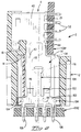
- FIGURE 7 is a longitudinal sectional view of the power module as shown in Figure 1, taken at right angles thereto;
- FIGURE 8 is a similar view to that of Figure 7 showing the connectors in mated relationship and being drawn to a larger scale than Figure 7;
- FIGURES 9 to 11 are elevational views of the mating ground contacts illustrating an alternative embodiment and showing respective stages in the mating of the ground contacts; and
- FIGURES 12 to 14 are end views of the contacts shown in Figures 9 to 11, respectively.
- FIGURE 15 is a diagrammatic view of an arrangement of power modules made in accordance with the invention and signal modules mounted on a mother board and a corresponding complementary arrangement of power and signal modules on a daughter board.
- FIGURE 16 is a cross-sectional view of the connector having an electrical contact made in accordance with the invention disposed within a contact-receiving passageway of the housing.
- FIGURE 17 is an enlarged fragmentary portion of Figure 16 illustrating part of the retention features.
- FIGURE 18 is a view similar to that of Figure 16 with the contact exploded from the housing.
- FIGURE 19 is a perspective view of the contact of Figure 16.
- FIGURE 20 is a flat plan view of the assembly face of the connector of Figure 16.
- FIGURE 21 is a sectional view taken along the line 6-6 of Figure 16.
- FIGURE 22 is an exploded view of Figure 21.
- FIGURE 23 is a sectional view of a mated connector assembly having the connector of the present invention mated to a complementary connector.
- FIGURE 24 is a perspective view of an alternative embodiment of the contact made in accordance with the present invention.
- FIGURE 25 is a perspective view of an electrical contact made in accordance with the invention and exploded from a circuit board.
- FIGURE 26 is a cross-sectional view of a connector assembly having a contact of Figure 25 disposed therein and mounted to a circuit board in one of its possible orientations.
- FIGURE 27 is a view similar to Figure 26 showing the electrical contact in its second polarized orientation.
- FIGURE 28 is a perspective view of a receptacle connector having a plurality of contacts of Figure 25 exploded from a circuit board.
- FIGURE 29 is a perspective view of an alternative embodiment of a receptacle connector having a single contact of Figure 25 and a plurality of other contacts.
- FIGURE 30 is an alternative embodiment of an electrical contact made in accordance with the invention.
- Reference will now be made to Figures 1 to 8. An electrical connector assembly in the form of an
electrical power module 2 comprises ablade connector 4 and areceptacle connector 6. Theblade connector 4 comprises an insulatinghousing 8 having abody 10 and ashroud 12 projecting forwardly from amating face 14 of thebody 10. As shown in Figures 7 and 8, thebody 10 defines a central,contact receiving cavity 16. Thebody 10 has two outer,contact receiving cavities 17, which are indicated in broken lines in Figure 1, onecavity 17 being disposed on each side of thecavity 16. Since thecavities cavity 16 will be described here. Thecavity 16 has a rearward, contact receiving,open side 18 and a laterallyopen side 20 adjacent thereto. Thebody 10 has anend wall 22 opposite to theopen side 20 andopposite side walls 24 adjacent to theside 20. Thecavity 16 hasopposite side walls 25, only one of which is shown (Figures 7 and 8). There projects rearwardly, from a forwardrudimentary wall 27 of thebody 10, rearwardly into thecavity 16, acontact retention rib 26. As shown in Figures 7 and 8, theshroud 12 projects rightwardly (as seen in Figures 7 and 8), beyond theopen side 20 of thecavity 16 to define, in cooperation with thebody 10, arecess 29. Eachcavity internal cavity 28 of theshroud 12. Theshroud 12 hasopposite side walls 30 andopposite side walls 32, having respective guide chamfers 34 and 36 at their forward ends. - A substantially uniplanar
ground blade contact 38, which is best seen in Figure 5, is secured in thecentral cavity 16. Theblade contact 38 best seen in Figure 5, comprises a rearwardblade support plate 40 and a forwardly projectingcontact blade 42 connected to theblade 40 by atransition neck 44. Theplate 40 has a rectilinearrear edge 46, from which extends at right angles thereto, alateral edge 48. There extend normally, from alateral edge 50 of theplate 40, opposite to theedge 48,compliant contact tails 52. Theplate 40 has a latchingtongue 54 proximate to theedge 48 and thetransition neck 44 has aretention boss 56 projecting in the same direction as thetongue 54. There projects forwardly from aforward edge 60 of theplate 40, aretention lug 58 having aretention barb 62 facing thetransition neck 44. Thecontact blade 42 has atab 64 projecting forwardly from theforward edge 66 of theblade 42. The width of thetab 64 is approximately one third of the overall width of theblade 42. As will be apparent from Figures 7 and 8, theground blade contact 38 was inserted through theopen side 18 of thecavity 16 with thetab 64 leading, so that theboss 56 pressed against theproximate side wall 25, the latchingtongue 54 engaging a shoulder (not shown) of theside wall 25 and thebarb 62 biting into theretention rib 26, theblade contact 38 being thereby secured in thecavity 16 with thecontact tails 52 projecting from theopen side 20 of thecavity 16 into therecess 29 and thecontact blade 42 projecting forwardly into acavity 28 of theshroud 12. Theconnector 4 further comprises a pair ofpower blade contacts 68, one of which is shown in Figure 6. Those parts of thecontact 68 which are identical with corresponding parts of thecontact 38 bear the same reference numerals as in thecontact 38. Eachcontact 68 differs from thecontact 38 in that thecontact blade 70 of thecontact 68 is devoid of thetab 64, having a rectilinearforward edge 71. Eachpower blade contact 68 is retained in a respective one of thecavities 17 in the same manner and in the same orientation as theground blade contact 38 is retained and oriented in itscavity 16. Thus, thecontact blades 70 project forwardly into thecavity 28 of theshroud 12 and thecontact tails 52 of eachcontact 68 project from thehousing body 10 in parallel relationship with the contact tails of theground contact 38. - With the
contacts housing 8 as described above, theconnector 4 is mounted to the edge of a first circuit board CB1 such thatboard CB 1 is positioned in therecess 29 with thecontact tails 52 of theground contact 38 extending through plated holes in the board CB1 and electrically connected to a ground conductor or ground conductors (not shown) thereon by means of a compliant portion, solder or other means as known in the art. Thecontact tails 52 of thepower contacts 68 extending through further plated through holes in the board CB1 and electrically connected to power conductors thereon. - The
receptacle connector 6 comprises an insulatinghousing 72 for mating reception to theshroud 12 of theconnector 4. Thehousing 72 has amating face 74, acontact receiving face 76 opposite thereto,opposite side walls 78 andopposite end walls 80. Thehousing 72 defines a centralcontact receiving cavity 82 and a lateralcontact receiving cavity 84 on each side thereof. Eachcavity blade guide slot 86 in themating face 74, and opens at its rear end into thecontact receiving face 76. Thecentral cavity 82 is separated fromcavities 84 bypartitions 88. As shown in Figures 7 and 8, eachend wall 80 has avertical slot 98 extending between thefaces outer edge 100 proximate to theface 76. - In each of the
cavities identical receptacle contact 96 which is best shown in Figures 5 and 6. Eachcontact 96 comprises a rearwardelongate base 102 having at each end thereof aretention boss 104. There depend from the rear edge of the base 102compliant contact tails 106 identical with thecontact tails 52 of thecontacts base 102, acontact spring 108 having an inwardly bowed, smoothly arcuate,transverse contact surface 110 surmounting a forwardly extendingspring arm 112. Thecontact surface 110 is of substantially the same width as thetab 64. Afurther contact spring 114 comprises a pair ofspring arms 116 each extending from the forward edge of thebase 102, on opposite sides of thecontact spring 108 and being joined at their forward ends by astrap 118 having an inwardly bowed, smoothly arcuate,transverse contact surface 120, spaced slightly forwardly of thecontact surface 110. Thecontact surface 120 is of substantially the same width as thecontact blade 42. Eachspring arm 116 has abent portion 122 proximate to the base 102 laterally offsetting thearm 116 from thecontact spring 108, whereby anopening 124 is provided near thebase 102, between the contact springs 108 and 114. Contact springs 108 and 114 converge slightly in the forward direction. Eachcontact 96 is inserted into its cavity in thehousing 72 by way of thecontact receiving face 76, with the end portions of the base 102 received in the rear end portions of theslots 98, and thebosses 104 engaged against the slot walls. Thecontact 96 is thereby temporarily retained in position in their cavities while thecontact tails 106 are inserted through plated through holes in a second circuit board CB2 and are electrically connected to respective conductors (not shown) thereon. The contact tails of the receptacle contact in thecavity 82 are electrically connected to a ground conductor or ground conductors on the board CB2, while the contact tails of thecontacts 92 in thecavities 84 are electrically connected to respective power conductors in the board CB2. - The mating of the
connectors connectors blade contact surfaces respective receptacle contact 96. When theconnector 4 is advanced to the position of Figure 2, theforward edge 71 of eachblade 70 then enters theguide slot 86 of arespective cavity 84 and theforward edge 66 of theblade 42 enters theguide slot 86 of thecavity 82. Thetab 64, however, which projects forwardly from theedge 66 of theblade 62 engages between both of the contact surfaces 110 and 120 of theground receptacle contact 96 in thecentral cavity 82 of thehousing 72. The ground circuit of thepower module 2, is therefore made before the power circuit thereof, since theblades 70 are, at this time, spaced from thepower contacts 96. When theconnector 4 is advanced to the position of Figure 3, each of theblades respective contact 96, whereby the power circuit of themodule 2 is also made. Thetab 64 then lies betweenspring arms ground contact 96 in thecavity 82. When theconnector 4 has been advanced to its fully mated position with theconnector 6, as shown in Figures 4 and 8, with themating face 14 of theconnector 4 engaging themating face 74 of thehousing 72, the forward edges 66 and 71 of theblades bent portions 122 of thecontacts 96, thehousing 72 of theconnectors 6 being then fully received in thecavity 28 of theshroud 12. As theconnector 4 is advanced from the position of Figure 3 to that of Figure 4, thetab 64 passes through theopening 124 between the contact springs 108 and 114 of thecontact 96 in thecavity 82, so as to lie beside thebase 102 of thecontact 96. As theconnectors connector 4 is retracted between the positions of Figures 4, 3, 2 and 1 respectively. In the position of Figure 2 theblade 42, by way of itstab 64, enters between the contact surfaces 110 and 120 of thecontact 96 in thecavity 82 after theblades 70 have been retracted from thecontacts 96 in thecavities 84. Thus, the ground circuit of themodule 2 remains made, until after the power circuit of the module has been broken. As the contact blades disengage from their receptacle contacts substantially simultaneously the power module no longer has its full current load. - When the blades are inserted between the contact surfaces 110 and 120, the
spring arms contacts 96 are cammed resiliently apart as shown in Figures 2 and 3. The blade insertion forces are, however, reduced because the contact surfaces 110 and 120 are offset from each other in the mating direction. Since theblades 70 have no tabs projecting therefrom, the contacts in thecavities 84 need not be identical with thecontact 96 in thecavity 82, but may be conventional contacts of the tulip type, for example. In the interest of manufacturing, inventory keeping, and convenience, however, all of the receptacle contacts are preferably identical. - The
connectors - The
contacts receptacle contacts 96, the contact springs 108 and 114 must be spaced by a certain minimum gap in the interest of forming and plating requirements. Thus, if there is to be a sufficient normally acting force between a blade and a receptacle contact, the blade must be of a maximum thickness which is compatible with said gap. Nevertheless, in the interest of economy of metal, the thickness of the metal stock from which the blade contacts are stamped, is preferably less than said maximum thickness. - Another embodiment of the
blade contact 38, which enables such economy to be achieved, will now be described with reference to Figures 9 to 14, in which those parts which are identical with corresponding parts of thecontact 38 described above, bear the same reference numerals as said corresponding parts. A blade contact 38' shown in Figures 9 to 14, differs from theblade contact 38, described above, in that the part of the blade 42' which passes between the contact surfaces 110 and 120 of thereceptacle contact 96 is formed with elongate, laterally aligned raisedareas forward edge 66 of the contact blade 42'. The raisedareas area 142 which is located between theareas receptacle contact 96 before thetab 64 is inserted between the contact springs 108 and 114, with the contact surfaces 110 and 120 thereof defining said minimum gap. Figures 10 and 13 show thetab 64 inserted between the contact surfaces 110 and 120, the contact springs 108 and 114 being thereby resiliently deflected to produce a moderate normal contact force between thetab 64 and the contact surfaces 110 and 120. When, as shown in Figures 11 and 14, the blade 42' is inserted into thereceptacle 96, the raisedareas areas contact surface 120 near the ends of the strap, in line with spring beams 114. and the raisedarea 142 wipes thecontact surface 110. The raisedareas contact blades 70 of theblade contacts 68. The blade contact 38' also differs from theblade contact 38 in that itssupport plate 40 is formed with aretention rib 146 instead of with the latchingtongue 54. - Figure 15 illustrates an arrangement of
blade connectors 4 andsignal receptacles 5 mounted to daughter board CB3 and a complementary arrangement ofreceptacle connectors 6 and headers 7 mounted to mother board CB4. The arrangements also showguide modules respective connectors complementary connectors 6,7 on mother board CB4. Figure 15 also illustrates thathousing 8 ofblade connector 4 extends beyond thehousing 9 ofreceptacles 5 and that thehousing 72 ofconnector 6 is shorter thathousing 73 of header 7. The leading edge ofhousing 8 is beveled at 34 to minimize stubbing ofhousing 8 with thecorner 75 ofhousing 73 as the respective connectors are mated. - The embodiments described above could be modified in various ways, for example each connector could be provided with both blade contacts and receptacle contacts.
- The details of the features that stabilize
contacts 38 withinrespective channels 16 ofhousing 8 ofblade connector 4 are discussed with reference to Figures 16 through 23. Thehousing 8 has amating face 14 adapted to mate with a complementary electrical connector such asconnector 6 shown in Figure 23, anassembly face 15 adapted to receive at least oneelectrical contact 38 therein and athird face 23 adapted for establishing electrical connection with a complementary electrical article such ascircuit board 90 shown in Figure 23. Theassembly face 15 is opposed from themating face 14 and thethird face 23 is at right angles to themating face 14.Housing 8 includes at least one contact-receivingpassageway 16 extending from theassembly face 15 to themating face 14. Thepassageway 16 further has a contact-receivingslot 20 open to thethird face 23 and to theassembly face 15 as best seen in Figure 20. -
Electrical contact 38, as best seen in Figures 16, 18 and 19, includes a first connectingportion 42 exposed at themating face 14 for an electrical engagement with complementary connector, a second connectingportion 52 being at right angles to the first connectingportion 42 and adapted for electrical connection to an electrical article and anintermediate body portion 35. In the preferred embodiment first connectingportion 42 is a blade and the second connectingportion 52 is a plurality of compliant tails, which can be press fit into respective through-holes of a circuit board. The compliant section of the contact tails may be of the ACTION PIN design available from AMP Incorporated, which can be press fit into position. It is to be understood that other press-fit or compliant tail designs may also be used as well as solder tails, if so desired. - In the preferred embodiment
intermediate body portion 35 includes anembossment 56 which is used to positioncontact 38 againstsidewall 37 within contact-receivingpassageway 16 proximate the mating face end of thepassageway 16. By holding thecontact 38 securely against thesidewall 37 of the contact-receivingpassageway 16, alignment of the first connectingportion 42 of thecontact 38 at themating face 14 is assured. Furthermore, the use of anembossment 56 on thebody portion 35 allows the width of thepassageway 16 to be greater than the thickness of thecontact 38 thereby permitting the first connectingportion 42 to move freely through thepassageway 16 during connector assembly, thus avoiding damage to any plating thereon. -
Connector 38 further includes a retention section orarm 53 remote from and opposite the second connectingportion 42 and associated with acooperable housing portion 33 when thecontact 38 is assembled intopassageway 16 via theassembly face 15.Cooperable housing portion 33 is opposite from thethird face 23 and includes a respective contact-retention channel 16a in communication with a corresponding one of the contact-receivingpassageways 16. Thecontact retention channels 16a extend forwardly intohousing 8 from theassembly face 15 toward themating face 14 and ending rearwardly thereof. Eachretention channel 16a has a width corresponding generally to the thickness of thecontact 38 so thatchannel 16a is adapted to receive aretention section 53 ofcontact 38. As can be seen in Figure 18, theretention channel 16a of the housing further includes a shortercontact positioning channel 21 at therearward end 40 thereof extending from theassembly face 15 toward themating face 14 and into anadjacent sidewall 37 of contact-receivingpassageway 16.Channel 21 is adapted to receive a cooperable portion ofcontact 38 as more fully explained below. - The
contact retention section 53 ofcontact 38 has abarb 62 at theleading end 58 thereof which is receivable in theforward end 16b of thehousing channel 16a, thebarb 62 being dimensioned to create an interference fit with theforward channel end 16b when thecontact 38 is assembled into thehousing 8. Thebarb 62 causes thecontact 38 to resist rearward movement after full assembly of thecontact 38 into the contact-receivingpassageway 16. As can be seen in Figures 16 and 18, upon inserting thecontact 38 into contact-receivingpassageway 16 fromassembly face 15, the first connecting portion, shown here as ablade 42, which is wider that the rearward portion of thehousing 8, is received into and passes throughslot 20 and enters the forward housing portion orshroud 12. The second connectingportion 52, shown in this example as four compliant contact sections or tails, is received in therespective slot 20 as the contact is moved forward into the housing. Theretention section 53 enters thechannel 16a until thecontact stop surface 60 engageshousing stop surface 31 within thehousing 8. When fully inserted, the leadingend 58 ofretention section 53 is disposed inforward channel section 16b andembossment 56 holds thecontact body 35 againstsidewall 37. As seen in Figures 16 and 17 theretention barb 62 engages the interior portion ofslot portion 16b to secure thecontact 38 in the contact-receiving 16 and resist rearward movement of thecontact 38 from thehousing 8. - In the preferred
embodiment retention section 53 of thecontact 38 further includes an outwardly directedlance 54, which extends outwardly in the same direction asembossment 56 and is received in contact-positioning channel portion 21. The contact-positioningchannel 21 is adapted to receive the outwardly extendinglance 54 of thecontact 38 and as shown in Figures 20, 21 and 22. Thelance 21 andembossment 56 assure that the planar surface ofcontact 38 is held securely againstinner wall 37 ofpassageway 16 thereby securely positioningcontact 38 withinpassageway 16 and preventingcontact 38 from moving sideways inpassageway 16, thus keeping the first connectingportion 42 in alignment for mating withcomplementary contacts 96 incomplementary connector 6, as seen in Figure 23. As shown in Figure 20contact 38 is retained and positioned within the respective contact-receivingpassageway 16 and is substantially "hung" or suspended from contact-retention channel 16a by theretention portion 53 with the second connectingportion 52, with the plurality of contact tails extending outwardly of thehousing 8 through theslot 20. - Figure 20 shows the assembly face of a connector adapted to receive three contacts of the
type 38, one of contact-receivingpassageways 16 having acontact 38 disposed therein. Figures 21 and 22 are sectionalviews illustrating channel 16a, and contact-positioningchannel 21 and the positions of the contact-retention section 58 inchannel 16a andlance 54 in contact-positioningchannel 21. These figures further show onecontact 38 forced against thesidewall 37 of contact-receivingpassageway 16 to stabilize the position of thecontact 38 within thehousing 8. - Figure 23 is a sectional view of
connector 4 and onecontact 38 secured inhousing 8 with the four contact tails of second connectingportion 52 engaged in and respective throughholes 92 ofcircuit board 90. As can be seen from Figure 23 the forward portion ofhousing 8 defines ashroud 12 for receiving themating connector 6, a portion of theshroud 12 extending beyond and below thecircuit board 90.Mating connector 6 is mounted tocircuit board 250 via a plurality of contact tails. - Figure 24 is an
alternative embodiment 438 of the contact made in accordance with the invention in which the second connectingportion 452 is a tabular like member which is received into contact-receivingslot 20 upon assembly to thehousing 8. Contact 438 includes anembossment 56 on thecontact body 35, and abarb 462 and an outwardly directedembossment 454 on the retention section, which are received in thehousing passageway 16 andchannel 16a in the same manner asembossment 56 andbarb 62 andlance 54 respectively, and help to stabilize first connectingportion 442 of thecontact 438 in the same manner as previously described. - The present invention will be illustrated with reference to a
receptacle contact 96 of the type suitable for use when conducting power, ground or signals. It is to be understood that the self-polarizing feature may be used with contacts of other configurations. Theelectrical contact 96 of Figures 5, 6 and 25 includes abody portion 102 having first and second connectingsections body portion 102 has opposed first and secondmajor surfaces edges section 106 includes a plurality ofcontact legs edge 105a of thebody portion 102. Thefirst leg 132 of this array of contact legs is spaced from asecond leg 134 at a first selected distance d1. Thesecond leg 134 is spaced from thethird leg 136 by a selected second distance d2 and the third andfourth legs fourth legs holes circuit board 150. For purposes of illustrating the invention the second connecting section is shown as an arrangement ofspring arms - The contact of the present invention is preferably stamped and formed from a flat strip of metal such as phosphor bronze or other suitable materials having the desired spring characteristics. The
contact 96 being a substantially flat member is readily reversed in a housing arrangement to provide a different polarization arrangement for a different pattern on the circuit board. - Figures 26 and 27 show a representative
electrical connector 6 including ahousing 72 having amating face 74, a mountingface 76 and acontact receiving cavity 83 configured to receiveelectrical contact 96. These figures show aconnector assembly 6 mounted torespective circuit boards contact 96 in its two polarized orientations. Figure 26 showselectrical contact 96 in a first orientation with the assembly mounted to board 150 with the firstterminal leg 132 disposed in through-hole 152 and the second, third andfourth contact legs holes contact terminal 96 is shown oriented tocircuit board 250 with the firstterminal leg 132 disposed in through-hole 252 and the second, third and fourthterminal legs holes - Figure 28 illustrates a
power receptacle connector 6 exploded from acircuit board 150.Connector 6 has twocontacts 96 disposed inrespective cavities 83 and onecontact 96 exploded fromhousing 72 and in alignment with respective through-holes incircuit board 150. As can be seen from this figure, the threecontacts 96 and specifically thefirst leg 132 of each of the three identical contacts orient theconnector 6 in a specific way to assure proper positioning of the connector on the circuit board. - Figure 29 shows an alternative embodiment 6' of a connector assembly having one
contact 96 and a plurality ofsignal contacts 370. The receptacle connector 6' includes ahousing 172 having amating face 274, a mounting face 276, acavity 283 configured to receiveterminal 96, and a plurality ofcavities 383 configured to receiverespective contacts 370.Circuit board 350 includes a column of through-holes respective contact legs contact 96 in a polarized orientation and an array of signal through-holes 372 for receiving the array ofpin terminals 370. - Figure 30 shows an
alternative embodiment 296 of a contact made in accordance with the invention. This contact includes abody 202 having first and second connectingportions legs common edge 205a ofbody 202.First leg 232 is spaced a distance d1' fromsecond leg 234, which in turn is spaced a distance d2' fromthird leg 236. - As can be seen from the foregoing discussion the contact terminals of the present invention are self polarizing, cost effective to manufacture and eliminate the need for additional polarization features for mounting a connector to a circuit board.
Claims (17)
- A pair of mating electrical contacts (38,96), comprising a blade contact (38) having a rearward blade support (40) for retention in a first insulating housing (8), and a contact blade (42) of a first width projecting forwardly from the blade support (40); and a receptacle contact (96) having a rearward base (102) for retention in a second insulating housing (72), and first and second contact springs (108,114) projecting forwardly from said base (102), the first contact spring (108) having a first transverse contact surface (110) and the second contact spring (114) having a second transverse contact surface (120) of a width which is substantially greater than said first width, the mating contacts (38,96) being characterized in that:said blade contact (38) has a tab (64) of a second width which is substantially less than said first width, projecting forwardly from a forward edge (66) of the contact blade (42); andthe second contact spring (114) of said receptacle contact (96) defines a rearward opening (124) for receiving the tab (64);said first and second contact surfaces (110,120) of said receptacle contact (96) cooperate to apply contact forces initially to the tab (64), and then to the contact blade (42) as the contacts (38,96) are being mated.
- A pair of mating contacts (38,96) as claimed in claim 1, wherein the width of the contact surface (110) of the first contact spring (108) is substantially equal to the width of the tab (64) and the width of the contact surface (120) of the second contact spring (114) is substantially equal to the width of the contact blade (40).
- A pair of contacts (38,96) as claimed in claim 1, wherein the tab (64) projects centrally from a forward edge (66) of the contact blade (42).
- A pair of contacts (38,96) as claimed in claim 1, wherein the second contact spring (114) comprises a pair of spring arms (116) connected to said base (102) on opposite sides of the first contact spring (108), and a strap (118) connecting the spring arms (116), the strap (118) being bowed towards the first contact spring (108) to define the second contact surface (120) which is continuous.
- A pair of contacts (38,96) as claimed in claim 1, wherein the blade support (40) of the blade contact (38) is a plate which is coplanar with the contact blade (42) and the tab (64), the support (40) having compliant contact tails (52) projecting from an edge (50) of the plate transversely of the contact blade (42).
- A pair of contacts (38',96) as claimed in claim 1, wherein the contact blade (42') is formed with raised areas (140,142,144) extending longitudinally of the contact blade (42') and projecting on opposite sides of the plane of the contact blade (42') for engaging the contact surfaces (110,120) of the contact springs (108,114) of the receptacle contact (96).
- An electrical connector assembly (2) comprising mating electrical connectors (4,6) having a ground blade contact (38) for mating with a ground receptacle contact (96) and current transmitting blade contacts (68) for mating with respective current transmitting receptacle contacts (96), the ground blade contact (38) having a contact blade (42), each current transmitting blade contact (68) having a contact blade (70) for engaging with the respective current transmitting receptacle contacts (96) as the contact blade (42) of the ground blade contact (38) engages with the ground receptacle contact (96), said assembly (2) being characterized in that:said ground blade contact (38) has a projecting tab (64) which is narrower than the contact blade (42), for engaging with the ground receptacle contact (96) before the contact blade (42) engages with the ground receptacle contact (96); andsaid ground receptacle contact (96) has an opening for receiving the tab (64) as the contact blades (42,72)are being mated with the receptacle contacts (96).
- An assembly (2) as claimed in claim 7, wherein the ground receptacle contact (96) has a first and a second contact spring (108,114) upstanding from a base (102), the first contact spring (108) having a contact surface (110) of substantially same width, transversely of said contact spring (108), as the tab (64), and the second contact spring (114) having a contact surface (120) of substantially the same width, transversely of that contact spring (114), as the contact blade (42) of the ground blade contact (38).
- An assembly (2) as claimed in claim 7, wherein each blade contact (38,70)is substantially coplanar, and has a contact blade support plate (40,40) retained in a cavity (16) in an insulating housing (8) of the respective connector (4), at least one contact tail (52) projecting from a lateral edge (50) of the support plate and being electrically connected to a conductor on a circuit board CB1.
- A right angle electrical connector (4) including a housing (8) having a mating face (14), an assembly face (15) opposed from said mating face (14) for receiving at least one electrical contact (38) therein, and a third face (23) at right angles to said mating face (14) for establishing electrical connection with a complementary electrical article (90), said housing (8) including at least one contact-receiving passageway (16) extending from said assembly face (15) to said mating face (14) and, an electrical contact (38) disposed in an associated one of said at least one housing passageway (16), each said contact (38) having a first connecting portion (42) exposed at said mating face (14) and a second connecting portion (52) at right angles said first connecting portion (42) and extending from said third face (23) and outwardly from said housing (8) for electrical connection to said electrical article (90); said connector (4) being characterized in that:said contact-receiving passageway (16) includes a contact-receiving slot (20) open to said third face (23) and to said assembly face (15);said contact (38) includes a retention section (53) remote from and opposite said second connecting portion (52)and associated with a cooperable housing portion (33)thereat,said cooperable housing portion (33)being opposite from said third face (23) and defining a channel (16a) extending forwardly from said assembly face (15) toward said mating face (14) and in communication with said slot (20), said channel (16a) being adapted to receive said retention section (53) thereinto upon receiving said contact (38) from said assembly face (15) of said housing (8); andsaid contact retention section (53) having a barb (62) at a leading end thereof receivable in a forward end (16b) of said channel (16a) with said barb (62) dimensioned to create an interference fit to resist rearward movement of said contact (38) after full assembly of said contact (38) into said housing (8).
- The connector (4) of claim 10 wherein said contact (38) has a thickness and said contact-receiving passageway (16) has a width greater than the thickness of said contact (38), and wherein said contact (38) further includes an intermediate body portion having an outwardly directed protrusion (56) which is received in a forward end of said contact-receiving passageway (16) in an interference fit to hold said first connecting portion (42) in alignment at said mating face (14).
- The connector (4) of claim 10 or 11 wherein said contact retention section (53) of said contact (38) includes a lance (54) directed outwardly from a surface thereof, said lance (54) being received in a contact-positioning channel of said housing (8).
- The connector of claim 10 or 11 wherein said contact retention section (53) of said contact (38) includes an embossment (146) directed outwardly from a surface thereof, said embossment (146) being received in a contact-positioning channel of said housing.
- An electrical contact (96) includes a body portion (102) having first and second connecting sections (106,115) at opposite ends thereof; and at least three legs (132,134,136) extending from a common end of said body portion (102) altogether comprising one (106) of said first and second connecting sections (106,115) of said contact (96); the contact (96) being characterized in that:a first (132) of said at least three legs (132,134,136) is spaced from a second (134) of said at least three legs(132,134,136) a selected first distance (d1) and said second leg (134) is spaced from a third (136) of said at least three legs (132,134,136) a selected second distance (d2), said first distance (d1) being different from said second distance (d2);whereby said at least three legs (132,134,136) are adapted to be received in respective through-holes (152,154,156) of a circuit board (150) in a polarized arrangement.
- The electrical contact of claim 14 wherein said first distance (d1) is greater than said second distance (d2).
- A connector assembly (6,61) including a housing (172) and at least one electrical contact (96) having a body portion having first and second connecting sections (106,115) at opposite ends thereof; and at least three legs (132,134,136) extending from a common end of said body portion (102) altogether comprising one of said first and second connecting sections (106,115) of said contact (96), the assembly (6,61) being characterized in that:a first (132) of said at least three legs (132,134,136) of said at least one legs (132) is spaced from a second (134) of said at least three legs (132,134,136) a selected first distance (d1) and said second leg (134) is spaced from a third (136) of said at least three legs (132,134,136) a selected second distance (d2), said first distance (d1) being different from said second distance (d2);whereby said connector assembly thus defined need have no other polarizing feature.
- The connector assembly (6,61) of claim 16 further including at least one other electrical contact.
Applications Claiming Priority (6)
| Application Number | Priority Date | Filing Date | Title |
|---|---|---|---|
| US356620 | 1994-12-15 | ||
| US08/356,620 US5582519A (en) | 1994-12-15 | 1994-12-15 | Make-first-break-last ground connections |
| US41217795A | 1995-03-28 | 1995-03-28 | |
| US41204495A | 1995-03-28 | 1995-03-28 | |
| US412177 | 1995-03-28 | ||
| US412044 | 1995-03-28 |
Publications (3)
| Publication Number | Publication Date |
|---|---|
| EP0717468A2 true EP0717468A2 (en) | 1996-06-19 |
| EP0717468A3 EP0717468A3 (en) | 1998-01-28 |
| EP0717468B1 EP0717468B1 (en) | 2002-01-23 |
Family
ID=27408275
Family Applications (1)
| Application Number | Title | Priority Date | Filing Date |
|---|---|---|---|
| EP95308237A Expired - Lifetime EP0717468B1 (en) | 1994-12-15 | 1995-11-17 | Make-first-break-last ground connections |
Country Status (4)
| Country | Link |
|---|---|
| EP (1) | EP0717468B1 (en) |
| JP (1) | JP3647951B2 (en) |
| KR (1) | KR100406182B1 (en) |
| DE (1) | DE69525138T2 (en) |
Cited By (7)
| Publication number | Priority date | Publication date | Assignee | Title |
|---|---|---|---|---|
| DE19726856C1 (en) * | 1997-06-24 | 1998-10-08 | Siemens Ag | Flat-plug for electrical plug-in connections |
| EP1248325A2 (en) * | 2001-04-06 | 2002-10-09 | Northrop Grumman Corporation | Insulator coring and contact configuration to prevent pin stubbing in the throat of tuning fork socket connector contacts |
| WO2004019455A1 (en) * | 2002-08-21 | 2004-03-04 | Tyco Electronics Corporation | Multi-sequenced contacts from single lead frame |
| CN102025050A (en) * | 2009-09-10 | 2011-04-20 | 安费诺有限公司 | Multi-pathway connector for circuit boards |
| EP2355254A1 (en) * | 2010-02-02 | 2011-08-10 | Wilo Se | Connecting element with knife contact and press fit contact |
| EP2508902A1 (en) * | 2011-04-07 | 2012-10-10 | Yamaichi Electronics Deutschland GmbH | Test contactor for a circuit board, use and test method |
| CN111490420A (en) * | 2019-01-28 | 2020-08-04 | 泰连公司 | Power connector for bus |
Families Citing this family (13)
| Publication number | Priority date | Publication date | Assignee | Title |
|---|---|---|---|---|
| US5980321A (en) * | 1997-02-07 | 1999-11-09 | Teradyne, Inc. | High speed, high density electrical connector |
| KR100496165B1 (en) * | 1997-09-04 | 2005-09-08 | 삼성전자주식회사 | Shunt connector jig for hard disk drive |
| CN1230948C (en) * | 1999-06-29 | 2005-12-07 | 3M创新有限公司 | Power and guidance connector |
| JP2002063960A (en) * | 2000-08-16 | 2002-02-28 | Taiko Denki Co Ltd | Connecting terminal for large current and connector using it |
| DE102005010704B4 (en) * | 2005-03-09 | 2011-05-12 | Erni Electronics Gmbh | Spring bushing for miniature connectors |
| JP4814730B2 (en) * | 2006-08-30 | 2011-11-16 | 株式会社マックエイト | Connector between printed circuit boards |
| JP4960324B2 (en) * | 2008-09-24 | 2012-06-27 | ケル株式会社 | Mating type connector |
| JP5586192B2 (en) * | 2009-09-03 | 2014-09-10 | 矢崎総業株式会社 | Connector terminal |
| CN102157825B (en) * | 2011-01-13 | 2013-03-20 | 中航光电科技股份有限公司 | Power supply hole contact part, contact pieces thereof and electric connector |
| JP5466679B2 (en) * | 2011-09-13 | 2014-04-09 | 日立オートモティブシステムズ株式会社 | Electronic circuit device for electric actuator |
| JP2014147311A (en) * | 2013-01-31 | 2014-08-21 | Makita Corp | Working machine having operation pole |
| JP6990203B2 (en) * | 2019-03-07 | 2022-01-12 | ヒロセ電機株式会社 | Terminal and electrical connector with the terminal |
| JP7321878B2 (en) * | 2019-10-15 | 2023-08-07 | ヒロセ電機株式会社 | connector |
Citations (2)
| Publication number | Priority date | Publication date | Assignee | Title |
|---|---|---|---|---|
| FR1374648A (en) | 1963-10-31 | 1964-10-09 | Pirelli | electrical contract element |
| US5116230A (en) | 1991-04-09 | 1992-05-26 | Molex Incorporated | Coaxial cable connector |
Family Cites Families (4)
| Publication number | Priority date | Publication date | Assignee | Title |
|---|---|---|---|---|
| US4175821A (en) * | 1978-05-15 | 1979-11-27 | Teradyne, Inc. | Electrical connector |
| US4384754A (en) * | 1980-11-17 | 1983-05-24 | Amp Incorporated | Multi-plane connectors |
| US5169324A (en) * | 1986-11-18 | 1992-12-08 | Lemke Timothy A | Plug terminator having a grounding member |
| US5104329A (en) * | 1990-09-21 | 1992-04-14 | Amp Incorporated | Electrical connector assembly |
-
1995
- 1995-11-17 DE DE69525138T patent/DE69525138T2/en not_active Expired - Lifetime
- 1995-11-17 EP EP95308237A patent/EP0717468B1/en not_active Expired - Lifetime
- 1995-12-13 KR KR1019950049292A patent/KR100406182B1/en not_active IP Right Cessation
- 1995-12-14 JP JP32534495A patent/JP3647951B2/en not_active Expired - Lifetime
Patent Citations (2)
| Publication number | Priority date | Publication date | Assignee | Title |
|---|---|---|---|---|
| FR1374648A (en) | 1963-10-31 | 1964-10-09 | Pirelli | electrical contract element |
| US5116230A (en) | 1991-04-09 | 1992-05-26 | Molex Incorporated | Coaxial cable connector |
Cited By (10)
| Publication number | Priority date | Publication date | Assignee | Title |
|---|---|---|---|---|
| DE19726856C1 (en) * | 1997-06-24 | 1998-10-08 | Siemens Ag | Flat-plug for electrical plug-in connections |
| EP1248325A2 (en) * | 2001-04-06 | 2002-10-09 | Northrop Grumman Corporation | Insulator coring and contact configuration to prevent pin stubbing in the throat of tuning fork socket connector contacts |
| EP1248325A3 (en) * | 2001-04-06 | 2003-12-10 | Northrop Grumman Corporation | Insulator coring and contact configuration to prevent pin stubbing in the throat of tuning fork socket connector contacts |
| US6709298B2 (en) | 2001-04-06 | 2004-03-23 | Litton Systems, Inc. | Insulator coring and contact configuration to prevent pin stubbing in the throat of tuning fork socket connector contacts |
| WO2004019455A1 (en) * | 2002-08-21 | 2004-03-04 | Tyco Electronics Corporation | Multi-sequenced contacts from single lead frame |
| US6890214B2 (en) | 2002-08-21 | 2005-05-10 | Tyco Electronics Corporation | Multi-sequenced contacts from single lead frame |
| CN102025050A (en) * | 2009-09-10 | 2011-04-20 | 安费诺有限公司 | Multi-pathway connector for circuit boards |
| EP2355254A1 (en) * | 2010-02-02 | 2011-08-10 | Wilo Se | Connecting element with knife contact and press fit contact |
| EP2508902A1 (en) * | 2011-04-07 | 2012-10-10 | Yamaichi Electronics Deutschland GmbH | Test contactor for a circuit board, use and test method |
| CN111490420A (en) * | 2019-01-28 | 2020-08-04 | 泰连公司 | Power connector for bus |
Also Published As
| Publication number | Publication date |
|---|---|
| DE69525138D1 (en) | 2002-03-14 |
| JPH08255658A (en) | 1996-10-01 |
| EP0717468A3 (en) | 1998-01-28 |
| KR100406182B1 (en) | 2004-03-18 |
| DE69525138T2 (en) | 2002-08-22 |
| JP3647951B2 (en) | 2005-05-18 |
| KR960027070A (en) | 1996-07-22 |
| EP0717468B1 (en) | 2002-01-23 |
Similar Documents
| Publication | Publication Date | Title |
|---|---|---|
| US5582519A (en) | Make-first-break-last ground connections | |
| EP0717468B1 (en) | Make-first-break-last ground connections | |
| EP0795929B1 (en) | Electric connector assembly with improved retention characteristics | |
| US6296496B1 (en) | Electrical connector and method for attaching the same to a printed circuit board | |
| US5161987A (en) | Connector with one piece ground bus | |
| US5498167A (en) | Board to board electrical connectors | |
| US4781612A (en) | Socket for single in-line memory module | |
| US7074085B2 (en) | Shielded electrical connector assembly | |
| US4867690A (en) | Electrical connector system | |
| US6171126B1 (en) | Battery receptacle connector | |
| US5112233A (en) | Electrical connector having contact retention means | |
| US7351091B1 (en) | Header connector | |
| EP0436943A1 (en) | Improved card edge connector | |
| US4917614A (en) | Electrical connector for surface mounting onto circuit boards | |
| EP0305597B1 (en) | Strip contacts | |
| WO1997045896A1 (en) | Surface mountable electrical connector | |
| US20020142629A1 (en) | Board mounted electrical connector assembly | |
| US5980337A (en) | IDC socket contact with high retention force | |
| EP0365179B1 (en) | Electrical connector system | |
| US20030203679A1 (en) | Card edge connector with a conductive wire interconnecting power terminals of the connector | |
| US6764357B2 (en) | Electrical connector and method of assembling the same | |
| US5588878A (en) | Electrical receptacle assembly and spring contact therefor | |
| US4679890A (en) | Connector contact terminal | |
| US6629853B2 (en) | Self-aligning power connector system | |
| US6749445B1 (en) | Electrical connector with spacer |
Legal Events
| Date | Code | Title | Description |
|---|---|---|---|
| PUAI | Public reference made under article 153(3) epc to a published international application that has entered the european phase |
Free format text: ORIGINAL CODE: 0009012 |
|
| AK | Designated contracting states |
Kind code of ref document: A2 Designated state(s): DE FR GB IT NL SE |
|
| PUAL | Search report despatched |
Free format text: ORIGINAL CODE: 0009013 |
|
| AK | Designated contracting states |
Kind code of ref document: A3 Designated state(s): DE FR GB IT NL SE |
|
| RHK1 | Main classification (correction) |
Ipc: H01R 13/02 |
|
| 17P | Request for examination filed |
Effective date: 19980508 |
|
| 17Q | First examination report despatched |
Effective date: 19990526 |
|
| GRAG | Despatch of communication of intention to grant |
Free format text: ORIGINAL CODE: EPIDOS AGRA |
|
| GRAG | Despatch of communication of intention to grant |
Free format text: ORIGINAL CODE: EPIDOS AGRA |
|
| GRAH | Despatch of communication of intention to grant a patent |
Free format text: ORIGINAL CODE: EPIDOS IGRA |
|
| GRAH | Despatch of communication of intention to grant a patent |
Free format text: ORIGINAL CODE: EPIDOS IGRA |
|
| GRAA | (expected) grant |
Free format text: ORIGINAL CODE: 0009210 |
|
| REG | Reference to a national code |
Ref country code: GB Ref legal event code: IF02 |
|
| AK | Designated contracting states |
Kind code of ref document: B1 Designated state(s): DE FR GB IT NL SE |
|
| REF | Corresponds to: |
Ref document number: 69525138 Country of ref document: DE Date of ref document: 20020314 |
|
| ET | Fr: translation filed | ||
| PLBE | No opposition filed within time limit |
Free format text: ORIGINAL CODE: 0009261 |
|
| STAA | Information on the status of an ep patent application or granted ep patent |
Free format text: STATUS: NO OPPOSITION FILED WITHIN TIME LIMIT |
|
| 26N | No opposition filed | ||
| PGFP | Annual fee paid to national office [announced via postgrant information from national office to epo] |
Ref country code: FR Payment date: 20141118 Year of fee payment: 20 Ref country code: SE Payment date: 20141128 Year of fee payment: 20 Ref country code: GB Payment date: 20141127 Year of fee payment: 20 Ref country code: DE Payment date: 20141128 Year of fee payment: 20 |
|
| PGFP | Annual fee paid to national office [announced via postgrant information from national office to epo] |
Ref country code: NL Payment date: 20141126 Year of fee payment: 20 |
|
| PGFP | Annual fee paid to national office [announced via postgrant information from national office to epo] |
Ref country code: IT Payment date: 20141126 Year of fee payment: 20 |
|
| REG | Reference to a national code |
Ref country code: DE Ref legal event code: R071 Ref document number: 69525138 Country of ref document: DE |
|
| REG | Reference to a national code |
Ref country code: NL Ref legal event code: MK Effective date: 20151116 |
|
| REG | Reference to a national code |
Ref country code: GB Ref legal event code: PE20 Expiry date: 20151116 |
|
| PG25 | Lapsed in a contracting state [announced via postgrant information from national office to epo] |
Ref country code: GB Free format text: LAPSE BECAUSE OF EXPIRATION OF PROTECTION Effective date: 20151116 |