EP0558702B1 - Capteur de courant avec circuit magnetique a entrefer - Google Patents
Capteur de courant avec circuit magnetique a entrefer Download PDFInfo
- Publication number
- EP0558702B1 EP0558702B1 EP92916945A EP92916945A EP0558702B1 EP 0558702 B1 EP0558702 B1 EP 0558702B1 EP 92916945 A EP92916945 A EP 92916945A EP 92916945 A EP92916945 A EP 92916945A EP 0558702 B1 EP0558702 B1 EP 0558702B1
- Authority
- EP
- European Patent Office
- Prior art keywords
- coil
- branch
- gap
- circuit
- air
- Prior art date
- Legal status (The legal status is an assumption and is not a legal conclusion. Google has not performed a legal analysis and makes no representation as to the accuracy of the status listed.)
- Expired - Lifetime
Links
Images

Classifications
-
- G—PHYSICS
- G01—MEASURING; TESTING
- G01R—MEASURING ELECTRIC VARIABLES; MEASURING MAGNETIC VARIABLES
- G01R15/00—Details of measuring arrangements of the types provided for in groups G01R17/00 - G01R29/00, G01R33/00 - G01R33/26 or G01R35/00
- G01R15/14—Adaptations providing voltage or current isolation, e.g. for high-voltage or high-current networks
- G01R15/18—Adaptations providing voltage or current isolation, e.g. for high-voltage or high-current networks using inductive devices, e.g. transformers
- G01R15/183—Adaptations providing voltage or current isolation, e.g. for high-voltage or high-current networks using inductive devices, e.g. transformers using transformers with a magnetic core
Definitions
- the present invention relates to an electric current sensor comprising a magnetic circuit with an air gap and at least one electric coil arranged around a branch of this circuit, this branch having the shape of an elongated rectangular parallelepiped. More particularly, the invention applies to sensors of the above-mentioned type with open loop in which a Hall generator is arranged in the air gap of the magnetic circuit.
- the present sensors require two separate parts or stacks of two groups of sheet metal parts to allow the mounting of a coil on a branch of the magnetic circuit.
- Such a structure and the mounting method which results therefrom are expensive and make automatic mounting installations relatively complex, the major problem being the realization of a tangle of sheet metal parts during the assembly of the usual lamellar magnetic circuits.
- the invention aims to provide a current sensor with a cost price significantly lower than that of current sensors of the same type, and in particular to allow much simpler mounting of the coil (s) on the magnetic circuit.
- the current sensor according to the invention is characterized in that the magnetic circuit consists of a single piece, or by a corresponding stack of sheets of the same shape, and has an air gap extending parallel to the branch on which is disposed said coil, the height of this air gap being greater than the thickness of the coil measured transversely to the longitudinal direction of said branch, on one side thereof, so as to allow the establishment of the coil by passing it through the air gap.
- the sensor according to the invention may in particular comprise a self-supporting winding or a winding produced on an insulating support having, at least over the length supporting the winding, a U-shaped cross section, the open side of the U being oriented towards the inside the magnetic circuit.
- the support preferably comprises, at at least one of its ends, a flange, a portion of which, situated on the open side of the U of the part of the support carrying the coil, has a height less than that of the air gap.
- This portion of the flange may in particular have a lower height on the side facing the outside of the support than on the side facing the winding.
- the coil can be placed on a separate insulating support, itself placed around said branch of the circuit, this support having at least on one side of its cross section a thickness less than the height of the air gap, so as to allow it to be placed inside the coil by passing it through the air gap.
- At least a second coil can be placed inside a first coil, this second coil having a thickness, measured transversely to the longitudinal direction of said circuit branch on one side thereof, less than the height of the air gap, so as to allow the establishment of this second coil on said circuit branch by passing it through the air gap after the introduction of the first coil.
- the air gap is formed between a lateral part of a free end of the branch of the magnetic circuit carrying the coil (s), and a frontal part of a free end of a circuit branch essentially perpendicular to the branch carrying the coil (s).
- the branch perpendicular to that carrying the coil (s) may have an end of larger cross section than the sections of the other parts of the circuit.
- a part or a stack of sheets made of a magnetically permeable material is arranged in contact with parts of the circuit adjacent to the air gap, so as to constitute a magnetic bridge over the air gap.
- Fig. 1 shows a magnetic circuit 1 having an air gap 2, formed between the lateral part of the end of a branch 3 of the circuit and the front part of a free end of a branch 4 perpendicular to the branch 3.
- the height H of the air gap 2 is slightly greater than the thickness E of a coil 5 and the thickness D of a tubular insulating support 6.
- the magnetic circuit can be made of a piece of ferrite or, as illustrated in Fig. 2, by a stack of sheet metal parts, of the same shape, assembled to form such a circuit.
- the height of the air gap H makes it possible to introduce the coil 5 through this air gap, then, in a second step, to introduce the support 6 inside this coil by threading it onto the branch 3.
- Fig. 3 illustrates the case where two windings are superimposed on branch 3 of a magnetic circuit similar to that of FIG. 1 and partially shown in FIG. 4.
- a first winding 7 is constituted, for example, by a single flat turn 7, to which connection wires are welded 8.
- the turn 7 has a thickness E1 less than the height H of the air gap 2 of the circuit 3, and will be introduced first through this air gap.
- an insulating tube 8 ′ the external dimensions of which are slightly smaller than the internal dimensions of the coil 7, is similarly introduced and placed inside the coil 7.
- a winding 9 made on an insulating support 10 is then also introduced through the air gap 2 and placed inside the insulating tube 8.
- the body of the support 10, which carries the winding 9, has a cross section in the form of U whose open part is oriented towards the inside of the circuit 1. This makes it possible to give the winding 9 a maximum thickness corresponding to the height H of the air gap, since the support does not contribute to the total height of the coil 9, 10 on the part to pass through the air gap 2.
- a shim 11 ' is introduced, between the branch 3 of the circuit and the winding 9 at the location of the opening of the U of the support 10, to isolate the winding of the branch 3. This wedge 11 'is also introduced through the air gap.
- Fig. 4 also schematically shows a magnetically permeable part 1 ′ which can be arranged in contact with the parts of the circuit 1 adjacent to the air gap 2, in order to form a magnetic bridge or shunt on the air gap to improve the dynamic performance of the sensor, more particularly in the case of a sensor of the compensation type.
- Another embodiment of the circuit provides for this purpose to give at least at the end of the branch opposite the branch 3 a cross section larger than that of the rest of the circuit.
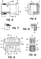
- Figs. 5 and 6 show the coil 9,10 of FIG. 3, the winding 9 being only partially indicated and the support 10 being shown partially in section.
- the two ends of the support 10 are constituted by flanges 11, 12 which have at the location of a respective portion 13, 14 a reduced section whose height corresponds to the thickness E2 of the coil 9.
- the portions 13, 14 correspond to the internal width of the U-shaped body of the support 10 and are intended to pass through the air gap 2 when the coil is put in place.
- the section of the portions 13, 14 can be trapezoidal as illustrated in FIGS. 5 and 6.
- Figs. 7 and 8 illustrate an alternative embodiment of the support 10 according to which an insulation wall 15 is part of the body of a support 16, this wall having a small thickness so as to reduce only slightly the maximum thickness E2 of the winding.
- a shim such as 11 'is generally no longer necessary.
- Figs. 9 and 10 illustrate an embodiment in which a magnetic circuit 17 is formed by a stack of C-shaped sheets. Two coils are disposed respectively on parallel branches 18 and 19 of this circuit, their positioning being effected similarly to the previous examples passing through the air gap 20 of this circuit.
- a coil 21 with thick wire is disposed on an insulating support 22 which in this case has a U-shaped cross section and can be inserted between the coil and the branch 19 from outside the circuit.
- a coil 23 comprises a coil 24 produced on a support 25 whose body carrying the coil also has a U shape open towards the inside of the circuit.
- Flanges 26, 27 are cut so as to allow the coil to pass through the air gap 20 with a thickness of the winding slightly less than the height of the air gap.
- An insulating intermediate piece 28 can be arranged beforehand on the branch 18 so that the coil 24 does not come into contact with this branch when the coil has been put in place.
- a shim 29 is introduced between the branch 18 and the support 25 from outside the circuit.
Landscapes
- Engineering & Computer Science (AREA)
- Power Engineering (AREA)
- Physics & Mathematics (AREA)
- General Physics & Mathematics (AREA)
- Coils Or Transformers For Communication (AREA)
- Measuring Magnetic Variables (AREA)
- Measuring Instrument Details And Bridges, And Automatic Balancing Devices (AREA)
- Geophysics And Detection Of Objects (AREA)
Abstract
Description
- La présente invention concerne un capteur de courant électrique comportant un circuit magnétique à entrefer et au moins une bobine électrique disposée autour d'une branche de ce circuit, cette branche ayant une forme de parallélépipède rectangle allongée. Plus particulièrement, l'invention s'applique à des capteurs du type susmentionné à boucle ouverte dans lesquels un générateur de Hall est disposé dans l'entrefer du circuit magnétique.
- Les présents capteurs, dont le circuit magnétique présente un seul entrefer, nécessitent deux pièces séparées ou des empilages de deux groupes de pièces de tôle pour permettre le montage d'une bobine sur une branche du circuit magnétique. Une telle structure et le procédé de montage qui en découle, sont coûteux et rendent les installations de montage automatique relativement complexes, le problème majeur étant la réalisation d'un enchevêtrement des pièces de tôle lors de l'assemblage des circuits magnétiques lamellaires usuels.
- L'invention vise à fournir un capteur de courant d'un prix de revient nettement inférieur à celui des capteurs actuels du même type, et à permettre notamment un montage beaucoup plus simple de la ou des bobines sur le circuit magnétique.
- A cet effet, le capteur de courant selon l'invention est caractérisé en ce que le circuit magnétique est constitué par une seule pièce, ou par un empilage correspondant de tôles de même forme, et présente un entrefer s'étendant parallèlement à la branche sur laquelle est disposée ladite bobine, la hauteur de cet entrefer étant plus grande que l'épaisseur de la bobine mesurée transversalement à la direction longitudinale de ladite branche, d'un côté de celle-ci, de façon à permettre la mise en place de la bobine en la faisant passer par l'entrefer.
- Le capteur selon l'invention peut notamment comporter un bobinage auto-portant ou un bobinage réalisé sur un support isolant ayant, au moins sur la longueur supportant le bobinage, une section transversale en forme de U, le côté ouvert du U étant orienté vers l'intérieur du circuit magnétique. Dans ce cas, le support comporte, de préférence, à au moins une de ses extrémités, un flasque dont une portion, située du côté ouvert du U de la partie du support portant le bobinage, possède une hauteur inférieure à celle de l'entrefer. Cette portion du flasque peut notamment posséder une hauteur plus faible du côté tourné vers l'extérieur du support que du côté tourné vers le bobinage.
- Selon la présente invention, la bobine peut être placée sur un support isolant séparé, lui-même placé autour de ladite branche du circuit, ce support ayant au moins sur un côté de sa section transversale une épaisseur inférieure à la hauteur de l'entrefer, de façon à permettre sa mise en place à l'intérieur de la bobine en le faisant passer par l'entrefer.
- Au moins une deuxième bobine peut être disposée à l'intérieur d'une première bobine, cette deuxième bobine ayant une épaisseur, mesurée transversalement à la direction longitudinale de ladite branche de circuit d'un côté de celle-ci, inférieure à la hauteur de l'entrefer, de façon à permettre la mise en place de cette deuxième bobine sur ladite branche de circuit en la faisant passer par l'entrefer après l'introduction de la première bobine.
- De préférence, l'entrefer est formé entre une partie latérale d'une extrémité libre de la branche du circuit magnétique portant la ou les bobines, et une partie frontale d'une extrémité libre d'une branche de circuit essentiellement perpendiculaire à la branche portant la ou les bobine(s). Dans ce cas, la branche perpendiculaire à celle portant la ou les bobine(s) peut comporter une extrémité de section transversale plus grande que les sections des autres parties du circuit.
- Selon une forme d'exécution particulière, une pièce ou un empilage de tôles en un matériau magnétiquement perméable est disposée en contact avec des parties du circuit voisines de l'entrefer, de façon à constituer un pont magnétique sur l'entrefer.
- L'invention sera mieux comprise à la lumière de la description suivante de différentes formes d'exécution, indiquées à titre d'exemple et illustrées dans le dessin annexé, dans lequel:
- La Fig. 1 est une vue latérale d'un circuit magnétique à entrefer muni d'une bobine, pour un capteur selon l'invention;
- La Fig. 2 est une vue de front du circuit de la Fig. 1;
- La Fig. 3 est une coupe transversale d'un circuit magnétique similaire muni de deux bobines superposées;
- La Fig. 4 est une vue partielle du circuit magnétique de la Fig. 3;
- La Fig. 5 est une vue latérale, partiellement en coupe, d'un support de bobine utilisable dans l'agencement de la Fig. 3;
- La Fig. 6 est une vue frontale, partiellement en coupe, selon la ligne VI-VI de la Fig. 5;
- La Fig. 7 est un détail illustrant une variante du support de la Fig. 5;
- la Fig. 8 est une vue partielle similaire à celle de la Fig. 6, pour la variante selon la Fig. 7;
- La Fig. 9 est une vue latérale d'un circuit magnétique portant deux bobines sur des branches différentes; et
- La Fig. 10 est une vue en coupe, selon la ligne X-X de la Fig. 9.
- La Fig. 1 montre un circuit magnétique 1 présentant un entrefer 2, formé entre la partie latérale de l'extrémité d'une branche 3 du circuit et la partie frontale d'une extrémité libre d'une branche 4 perpendiculaire à la branche 3. La hauteur H de l'entrefer 2 est légèrement supérieure à l'épaisseur E d'une bobine 5 et à l'épaisseur D d'un support isolant tubulaire 6. Le circuit magnétique peut être réalisé en une pièce de ferrite ou, comme l'illustre la Fig. 2, par un empilage de pièces de tôle, de même forme, assemblé pour former un tel circuit.
- La hauteur de l'entrefer H permet d'introduire la bobine 5 à travers cet entrefer, puis, dans une deuxième étape, d'introduire le support 6 à l'intérieur de cette bobine en l'enfilant sur la branche 3.
- La Fig. 3 illustre le cas où deux enroulements sont superposés sur la branche 3 d'un circuit magnétique similaire à celui de la Fig. 1 et représenté partiellement à la Fig. 4. Un premier enroulement 7 est constitué, par exemple, par une spire plate unique 7, à laquelle sont soudés des fils de connexion 8. La spire 7 possède une épaisseur E1 inférieure à la hauteur H de l'entrefer 2 du circuit 3, et sera introduite en premier à travers cet entrefer. Puis, un tube isolant 8', dont les dimensions extérieures sont légèrement inférieures aux dimensions intérieures de la spire 7, est introduit de façon similaire et disposé à l'intérieur de la spire 7.
- Un enroulement 9 réalisé sur un support isolant 10 est ensuite également introduit à travers l'entrefer 2 et placé à l'intérieur du tube isolant 8. Le corps du support 10, qui porte l'enroulement 9, présente une section transversale en forme de U dont la partie ouverte est orientée vers l'intérieur du circuit 1. Ceci permet de donner à l'enroulement 9 une épaisseur maximale correspondant à la hauteur H de l'entrefer, puisque le support ne contribue pas à la hauteur totale de la bobine 9, 10 sur la partie devant passer à travers l'entrefer 2. Enfin, une cale 11' est introduite, entre la branche 3 du circuit et l'enroulement 9 à l'endroit de l'ouverture du U du support 10, pour isoler l'enroulement de la branche 3. Cette cale 11' est également introduite par l'entrefer.
- La Fig. 4 montre en outre schématiquement une pièce 1' magnétiquement perméable qui peut être disposée en contact avec les parties du circuit 1 voisines de l'entrefer 2, afin de former un pont ou shunt magnétique sur l'entrefer pour améliorer les performances dynamiques du capteur, plus particulièrement dans le cas d'un capteur du type à compensation. Une autre forme d'exécution du circuit prévoit à cet effet de conférer au moins à l'extrémité de la branche en regard de la branche 3 une section transversale plus grande que celle du reste du circuit.
- Les Fig. 5 et 6 montrent la bobine 9,10 de la Fig. 3, l'enroulement 9 n'étant indiqué que partiellement et le support 10 étant représenté partiellement en coupe. Les deux extrémités du support 10 sont constituées par des flasques 11, 12 qui présentent à l'endroit d'une portion respective 13, 14 une section réduite dont la hauteur correspond à l'épaisseur E2 du bobinage 9. Les portions 13, 14 correspondent à la largeur intérieure du corps en forme de U du support 10 et sont destinées à passer par l'entrefer 2 au moment de la mise en place de la bobine. Pour faciliter l'insertion de l'ensemble par l'entrefer, la section des portions 13, 14 peut être trapézoïdale comme l'illustrent les Fig. 5 et 6.
- Les Fig. 7 et 8 illustrent une variante d'exécution du support 10 selon laquelle une paroi d'isolation 15 fait partie du corps d'un support 16, cette paroi ayant une épaisseur faible de manière à ne réduire que de peu l'épaisseur maximale E2 du bobinage. Dans ce cas, une cale telle que 11' n'est généralement plus nécessaire.
- Les Fig. 9 et 10 illustrent une forme d'exécution dans laquelle un circuit magnétique 17 est formé par un empilage de tôles en forme de C. Deux bobines sont disposées respectivement sur des branches parallèles 18 et 19 de ce circuit, leur mise en place s'effectuant d'une façon similaire aux exemples précédents en passant par l'entrefer 20 de ce circuit. Telle que montrée à titre d'exemple, une bobine 21 à fil épais est disposée sur un support isolant 22 qui en l'occurence présente une section transversale en forme de U et peut être insérée entre la bobine et la branche 19 de l'extérieur du circuit. Une bobine 23 comporte un bobinage 24 réalisé sur support 25 dont le corps portant le bobinage présente également une forme de U ouvert vers l'intérieur du circuit. Des flasques 26, 27 sont découpées de manière à permettre le passage de la bobine par l'entrefer 20 avec une épaisseur du bobinage légèrement inférieure à la hauteur de l'entrefer. Une pièce intermédiaire isolante 28 peut être disposée au préalable sur la branche 18 de façon que le bobinage 24 ne vienne pas en contact avec cette branche lorsque la bobine a été mise en place. En outre, une cale 29 est introduite entre la branche 18 et le support 25 de l'extérieur du circuit.
- Les exemples susmentionnés sont bien entendu nullement limitatifs et de nombreuses autres formes et variantes d'exécution sont du domaine de l'homme de métier.
Claims (10)
- Capteur de courant électrique comportant un circuit magnétique (1) à entrefer (2) et au moins une bobine électrique (5,9) disposée autour d'une branche (3) de ce circuit, cette branche ayant une forme de parallélépipède rectangle allongé, caractérisé en ce que le circuit magnétique (1) est constitué par une seule pièce, ou par un empilage correspondant de tôles de même forme, et présente un entrefer (2) s'étendant parallèlement à la branche (3) sur laquelle est disposée ladite bobine (5,9), la hauteur (H) de cet entrefer (2) étant plus grande que l'épaisseur (E) de la bobine (5,9) mesurée transversalement à la direction longitudinale de ladite branche (3), d'un côté de celle-ci, de façon à permettre la mise en place de la bobine en la faisant passer par l'entrefer (2).
- Capteur selon la revendication 1, caractérisé en ce que la bobine (5) comporte un bobinage autoportant.
- Capteur selon la revendication 1, caractérisé en ce que la bobine (9) comporte un bobinage réalisé sur un support isolant (10) ayant, au moins sur la longueur supportant le bobinage, une section transversale en forme de U, le côté ouvert du U étant orienté vers l'intérieur du circuit magnétique (1).
- Capteur selon la revendication 3, caractérisé en ce que le support (10) comporte, à au moins une de ses extrémités, un flasque (11) dont une portion située du côté ouvert du U de la partie du support portant le bobinage possède une hauteur inférieure à celle de l'entrefer.
- Capteur selon la revendication 4, caractérisé en ce que ladite portion du flasque (11) possède une hauteur plus faible du côté tourné vers l'extérieur du support que du côté tourné vers le bobinage.
- Capteur selon la revendication 1, caractérisé en ce que la bobine (5) est placée sur un support isolant (6) séparé, lui-même placé autour de ladite branche (3) du circuit, ce support (6) ayant, au moins sur un côté de sa section transversale, une épaisseur (D) inférieure à la hauteur (H) de l'entrefer (2), de façon à permettre sa mise en place à l'intérieur de la bobine, en le faisant passer par l'entrefer.
- Capteur selon l'une des revendications précédentes, caractérisé en ce qu'au moins une deuxième bobine (9) est disposée à l'intérieur d'une première bobine (7), cette deuxième bobine (9) ayant une épaisseur (E₂), mesurée transversalement à la direction longitudinale de ladite branche du circuit d'un côté de celle-ci, inférieure à la hauteur (H) de l'entrefer (2), de façon à permettre la mise en place de cette deuxième bobine sur ladite branche du circuit en la faisant passer par l'entrefer après l'introduction de la première bobine.
- Capteur selon l'une des revendications précédentes, caractérisé en ce que l'entrefer (2) est formé entre une partie latérale d'une extrémité libre de la branche (3) du circuit magnétique portant la ou les bobines, et une partie frontale d'une extrémité libre d'une branche (4) de circuit essentiellement perpendiculaire à la branche portant la ou les bobines.
- Capteur selon la revendication 8, caractérisé en ce que ladite branche (4) perpendiculaire à celle portant la ou les bobines, comporte une extrémité de section transversale plus grande que les sections des autres parties du circuit.
- Capteur selon l'une des revendications précédentes, caractérisé en ce qu'une pièce ou un empilage de tôles en un matériau magnétiquement perméable est disposé en contact avec des parties du circuit voisines de l'entrefer, de façon à constituer un pont magnétique sur l'entrefer (2).
Applications Claiming Priority (3)
| Application Number | Priority Date | Filing Date | Title |
|---|---|---|---|
| CH2789/91A CH685313A5 (fr) | 1991-09-20 | 1991-09-20 | Capteur de courant avec circuit magnétique à entrefer. |
| CH2789/91 | 1991-09-20 | ||
| PCT/CH1992/000163 WO1993006491A1 (fr) | 1991-09-20 | 1992-08-14 | Capteur de courant avec circuit magnetique a entrefer |
Publications (2)
| Publication Number | Publication Date |
|---|---|
| EP0558702A1 EP0558702A1 (fr) | 1993-09-08 |
| EP0558702B1 true EP0558702B1 (fr) | 1996-05-01 |
Family
ID=4241630
Family Applications (1)
| Application Number | Title | Priority Date | Filing Date |
|---|---|---|---|
| EP92916945A Expired - Lifetime EP0558702B1 (fr) | 1991-09-20 | 1992-08-14 | Capteur de courant avec circuit magnetique a entrefer |
Country Status (7)
| Country | Link |
|---|---|
| US (1) | US5446435A (fr) |
| EP (1) | EP0558702B1 (fr) |
| JP (1) | JP2851703B2 (fr) |
| CN (1) | CN1043818C (fr) |
| CH (1) | CH685313A5 (fr) |
| DE (1) | DE69210390T2 (fr) |
| WO (1) | WO1993006491A1 (fr) |
Cited By (3)
| Publication number | Priority date | Publication date | Assignee | Title |
|---|---|---|---|---|
| US7332903B2 (en) | 2005-08-25 | 2008-02-19 | Lisa Dräxlmaier GmbH | Device and method for measuring a current flowing in an electrical conductor |
| US7541799B2 (en) | 2005-05-25 | 2009-06-02 | Lisa Dräxlmaier GmbH | Method and device for measuring a current flowing in an electrical conductor |
| US7923986B2 (en) | 2006-07-14 | 2011-04-12 | Lisa Draexlmaier Gmbh | Device and method for measuring a current flowing in an electrical conductor |
Families Citing this family (11)
| Publication number | Priority date | Publication date | Assignee | Title |
|---|---|---|---|---|
| US5495169A (en) * | 1984-10-12 | 1996-02-27 | Smith; Dayle | Clamp-on current sensor |
| JP4745543B2 (ja) * | 2001-06-22 | 2011-08-10 | Necトーキン株式会社 | 磁芯およびコイル部品 |
| DE102004033089A1 (de) | 2004-07-08 | 2006-03-02 | Maschinenfabrik Kemper Gmbh & Co. Kg | Querförderschnecke für einen Erntevorsatz |
| MX2010001276A (es) * | 2009-01-30 | 2011-01-10 | Elster Solutions Llc | Metodo y aparato para medir la salida de corriente de transformadores de energia de distribucion de bajo voltaje montados sobre cojinete. |
| JP2011135091A (ja) * | 2011-02-16 | 2011-07-07 | Nec Tokin Corp | 磁芯およびコイル部品 |
| DE102011080034A1 (de) * | 2011-07-28 | 2013-01-31 | Vacuumschmelze Gmbh & Co. Kg | Stromsensoranordnung |
| DE102011080041A1 (de) * | 2011-07-28 | 2013-04-11 | Vacuumschmelze Gmbh & Co. Kg | Stromsensoranordnung |
| DE102014214433A1 (de) * | 2014-07-23 | 2016-01-28 | SUMIDA Components & Modules GmbH | Hochspannungskleintransformator mit U-förmigem Kern |
| CN106706990B (zh) * | 2017-02-28 | 2023-07-25 | 南京普肯传感科技有限公司 | 一种穿芯式霍尔电流传感器用磁芯气隙固定结构组件 |
| CN110609216B (zh) * | 2019-11-03 | 2021-04-13 | 西南交通大学 | 一种动车组电缆终端故障定位方法 |
| CN121986386A (zh) * | 2023-12-13 | 2026-05-05 | 株式会社村田制作所 | 线圈部件 |
Family Cites Families (11)
| Publication number | Priority date | Publication date | Assignee | Title |
|---|---|---|---|---|
| US1367988A (en) * | 1921-02-08 | replogle | ||
| US1863936A (en) * | 1931-07-06 | 1932-06-21 | August C Schwager | Transformer system and apparatus |
| FR737490A (fr) * | 1931-07-06 | 1932-12-12 | Appareil électrique avec noyau magnétique muni d'au moins un enroulement | |
| US1862613A (en) * | 1931-07-08 | 1932-06-14 | Yokogawa Electric Works Ltd | Split core current transformer |
| US2867785A (en) * | 1953-03-06 | 1959-01-06 | Ranza A Crumbliss | Ignition coil |
| US3284710A (en) * | 1962-07-03 | 1966-11-08 | Magnaflux Corp | A.c. or pulsating d.c. input signal current measuring transformer system with transformer output ratios corresponding to the input signal |
| JPS5134499Y2 (fr) * | 1971-07-29 | 1976-08-26 | ||
| FR2331029A1 (fr) * | 1975-11-05 | 1977-06-03 | Aerospatiale | Dispositif de mesure de l'intensite du courant electrique dans un conducteur |
| US4000483A (en) * | 1976-06-24 | 1976-12-28 | The Singer Company | Low voltage power transformer |
| US4654563A (en) * | 1984-03-28 | 1987-03-31 | Energy Technologies Corp. | Fluorescent lamp ballast |
| US4656452A (en) * | 1985-11-08 | 1987-04-07 | Rte Corporation | Transformer telephone influence tractor core shunt |
-
1991
- 1991-03-20 US US08/050,053 patent/US5446435A/en not_active Expired - Lifetime
- 1991-09-20 CH CH2789/91A patent/CH685313A5/fr not_active IP Right Cessation
-
1992
- 1992-08-14 WO PCT/CH1992/000163 patent/WO1993006491A1/fr not_active Ceased
- 1992-08-14 JP JP5505661A patent/JP2851703B2/ja not_active Expired - Lifetime
- 1992-08-14 DE DE69210390T patent/DE69210390T2/de not_active Expired - Fee Related
- 1992-08-14 EP EP92916945A patent/EP0558702B1/fr not_active Expired - Lifetime
- 1992-08-28 CN CN92110098A patent/CN1043818C/zh not_active Expired - Fee Related
Cited By (3)
| Publication number | Priority date | Publication date | Assignee | Title |
|---|---|---|---|---|
| US7541799B2 (en) | 2005-05-25 | 2009-06-02 | Lisa Dräxlmaier GmbH | Method and device for measuring a current flowing in an electrical conductor |
| US7332903B2 (en) | 2005-08-25 | 2008-02-19 | Lisa Dräxlmaier GmbH | Device and method for measuring a current flowing in an electrical conductor |
| US7923986B2 (en) | 2006-07-14 | 2011-04-12 | Lisa Draexlmaier Gmbh | Device and method for measuring a current flowing in an electrical conductor |
Also Published As
| Publication number | Publication date |
|---|---|
| CN1043818C (zh) | 1999-06-23 |
| DE69210390T2 (de) | 1997-01-02 |
| CN1070764A (zh) | 1993-04-07 |
| WO1993006491A1 (fr) | 1993-04-01 |
| JP2851703B2 (ja) | 1999-01-27 |
| CH685313A5 (fr) | 1995-05-31 |
| DE69210390D1 (de) | 1996-06-05 |
| JPH06502922A (ja) | 1994-03-31 |
| US5446435A (en) | 1995-08-29 |
| EP0558702A1 (fr) | 1993-09-08 |
Similar Documents
| Publication | Publication Date | Title |
|---|---|---|
| WO1993006491A1 (fr) | Capteur de courant avec circuit magnetique a entrefer | |
| EP0815456B1 (fr) | Capteur de courant electrique | |
| EP0429625B1 (fr) | Actionneur electromagnetique monophase de faible encombrement | |
| EP0313514B1 (fr) | Procédé de fabrication d'un stator sans rainures pour moteur électrique et moteur électrique comprenant un stator fabriqué selon le procédé | |
| EP0584295B1 (fr) | Procede de montage d'une bobine electrique sur un circuit magnetique a entrefer | |
| FR2617341A1 (fr) | Chemin de cables en treillis soude | |
| WO2007080301A1 (fr) | Actionneur electromagnetique a aimants permanents disposes en v selon un agencement electromagnetiquement optimise | |
| FR2618271A2 (fr) | Rotor a poles a griffes pour un generateur electrique, notamment un alternateur de vehicule automobile. | |
| FR2509083A1 (fr) | Transformateur muni d'un blindage magnetique | |
| EP0794545B1 (fr) | Interrupteur ou disjoncteur électrique sous vide | |
| FR2675953A1 (fr) | Agencement de connexion pour fils electriques et piece de connexion pour un tel agencement. | |
| EP0132208A1 (fr) | Pince d'ancrage pour câbles porteurs isolés à plusieurs conducteurs | |
| FR3098026A1 (fr) | Connecteur électrique solidarisé à un élément conducteur longiforme, notamment pour un dispositif de purification de gaz d’échappement | |
| EP2077571B1 (fr) | Contacteur électromagnétique | |
| CH459368A (fr) | Procédé d'aimantation de roues magnétiques pour engrenage magnétique et dispositif pour la mise en oevre du procédé | |
| FR2818001A1 (fr) | Bobine d'allumage a entrefer optimise | |
| EP0090881A1 (fr) | Ligature pour la retenue d'un câble électrique dans la gorge supérieure d'un isolateur rigide | |
| EP1955339B1 (fr) | Actionneur electromagnetique à aimants permanents disposes en v | |
| FR2694459A3 (fr) | Moteur à induit extérieur commuté électriquement pour l'entaînement d'appareils dans des véhicules à moteur. | |
| EP1020977A1 (fr) | Procédé d'assemblage d'un moteur électrique rotatif | |
| FR2460028A1 (fr) | Transducteur magnetique a aimant mobile | |
| FR2730849A1 (fr) | Transformateur, notamment pour convertisseur d'energie, et convertisseur d'energie a resonnance dote d'un tel transformateur | |
| FR2586324A1 (fr) | Electro-aimant a courant continu a mouvement de translation | |
| EP1497839A1 (fr) | Actionneur electromagnetique a aimant permanent | |
| FR2525308A1 (fr) | Dispositif antivibrations pour contacteur de demarreur pour moteurs a combustion interne |
Legal Events
| Date | Code | Title | Description |
|---|---|---|---|
| PUAI | Public reference made under article 153(3) epc to a published international application that has entered the european phase |
Free format text: ORIGINAL CODE: 0009012 |
|
| 17P | Request for examination filed |
Effective date: 19930510 |
|
| AK | Designated contracting states |
Kind code of ref document: A1 Designated state(s): DE FR GB |
|
| 17Q | First examination report despatched |
Effective date: 19951019 |
|
| GRAH | Despatch of communication of intention to grant a patent |
Free format text: ORIGINAL CODE: EPIDOS IGRA |
|
| GRAA | (expected) grant |
Free format text: ORIGINAL CODE: 0009210 |
|
| AK | Designated contracting states |
Kind code of ref document: B1 Designated state(s): DE FR GB |
|
| REF | Corresponds to: |
Ref document number: 69210390 Country of ref document: DE Date of ref document: 19960605 |
|
| GBT | Gb: translation of ep patent filed (gb section 77(6)(a)/1977) |
Effective date: 19960806 |
|
| PLBE | No opposition filed within time limit |
Free format text: ORIGINAL CODE: 0009261 |
|
| 26N | No opposition filed | ||
| REG | Reference to a national code |
Ref country code: GB Ref legal event code: IF02 |
|
| PGFP | Annual fee paid to national office [announced via postgrant information from national office to epo] |
Ref country code: GB Payment date: 20060824 Year of fee payment: 15 |
|
| GBPC | Gb: european patent ceased through non-payment of renewal fee |
Effective date: 20070814 |
|
| PGFP | Annual fee paid to national office [announced via postgrant information from national office to epo] |
Ref country code: DE Payment date: 20080822 Year of fee payment: 17 |
|
| PG25 | Lapsed in a contracting state [announced via postgrant information from national office to epo] |
Ref country code: GB Free format text: LAPSE BECAUSE OF NON-PAYMENT OF DUE FEES Effective date: 20070814 |
|
| PGFP | Annual fee paid to national office [announced via postgrant information from national office to epo] |
Ref country code: FR Payment date: 20080813 Year of fee payment: 17 |
|
| REG | Reference to a national code |
Ref country code: FR Ref legal event code: ST Effective date: 20100430 |
|
| PG25 | Lapsed in a contracting state [announced via postgrant information from national office to epo] |
Ref country code: FR Free format text: LAPSE BECAUSE OF NON-PAYMENT OF DUE FEES Effective date: 20090831 Ref country code: DE Free format text: LAPSE BECAUSE OF NON-PAYMENT OF DUE FEES Effective date: 20100302 |