EP0557962A1 - Collision avoidance system for carriages - Google Patents
Collision avoidance system for carriages Download PDFInfo
- Publication number
- EP0557962A1 EP0557962A1 EP93102865A EP93102865A EP0557962A1 EP 0557962 A1 EP0557962 A1 EP 0557962A1 EP 93102865 A EP93102865 A EP 93102865A EP 93102865 A EP93102865 A EP 93102865A EP 0557962 A1 EP0557962 A1 EP 0557962A1
- Authority
- EP
- European Patent Office
- Prior art keywords
- carriage
- light
- corner
- track
- collision avoidance
- Prior art date
- Legal status (The legal status is an assumption and is not a legal conclusion. Google has not performed a legal analysis and makes no representation as to the accuracy of the status listed.)
- Granted
Links
Images


Classifications
-
- G—PHYSICS
- G08—SIGNALLING
- G08G—TRAFFIC CONTROL SYSTEMS
- G08G1/00—Traffic control systems for road vehicles
- G08G1/22—Platooning, i.e. convoy of communicating vehicles
-
- B—PERFORMING OPERATIONS; TRANSPORTING
- B61—RAILWAYS
- B61L—GUIDING RAILWAY TRAFFIC; ENSURING THE SAFETY OF RAILWAY TRAFFIC
- B61L23/00—Control, warning, or like safety means along the route or between vehicles or vehicle trains
- B61L23/34—Control, warnings or like safety means indicating the distance between vehicles or vehicle trains by the transmission of signals therebetween
-
- G—PHYSICS
- G08—SIGNALLING
- G08G—TRAFFIC CONTROL SYSTEMS
- G08G1/00—Traffic control systems for road vehicles
- G08G1/16—Anti-collision systems
- G08G1/161—Decentralised systems, e.g. inter-vehicle communication
- G08G1/163—Decentralised systems, e.g. inter-vehicle communication involving continuous checking
Definitions
- the present invention relates to a collision avoidance system for carriages on a rail, and particularly to a system for preventing the collision of carriages in a curved portion of the rail.
- a plurality of carriages are moved in series on an endless loop-like rail to automatically carry loads from a loading station to an unloading station.
- a loading station C which generally comprises a plurality of conveyors as indicated by the arrows
- an unloading station D which generally comprises a plurality of conveyors as indicated by the arrows
- the endless track 1 includes two straight segments 1b and 1c and two curved segments 1a and 1d.
- the track 1 is formed by a pair of endless rails 2 and 3.
- a plurality of carriages ( Figure 13 only illustrates four of them: 4A-4D) move along the track 1 to carry loads from the loading station C to the unloading station D.
- Each carriage 4 has four wheels 5, 6, 7 and 8, and the two outer wheels 5 and 6 roll on the outer rail 3 and the two inner wheels 7 and 8 roll on the inner rail 2.
- the outer rail 3 is used as a reference rail.
- a propulsion shaft 9 extends between the rails 2 and 3.
- a pair of drive wheels 11 and 12 mounted on the carriage 4 rotate as the propulsion shaft 9 rotates, and the' rotation of the drive wheels 11 and 12 result in the propulsion of the carriage 4.
- the collision avoidance between the carriages 4A-4D is the requisite for a safety automatic loading and unloading operation.
- a sensor for detecting a preceding carriage may be employed.
- the sensor mounting position is the carriage itself and an optical sensor unit (a pair of light emitting element and a light detector) is used.
- a light emitting element 13 is mounted on the back of each carriage and a light detector 14 is mounted on the front of the same such that when a plurality of carriages move in line on a single track, as shown in Figure 13, the detector 14 of a carriage can detect a light P emitted from a preceding carriage.
- the conventional light emitting sensor 13 emits the light P straight or in a very small angle. Therefore, the carriage 4D can always receive the light from the preceding carriage 4C since these carriages are in the straight line 1b whereas the carriage 4B cannot always receive the light from the preceding carriage 4A since these two carriages 4A and 4B are in the corner section 1a.
- the carriage 4B can detect the light P from the preceding carriage 4A only when the carriage 4B reaches in the vicinity of the carriage 4A. As a result, when the sensor 14 of the carriage 4B detects the optical signal P from the carriage 4A, the distance between the two carriages 4A and 4B is too close to avoid the collision. If the radius of the corner 1a is reduced to save the space, the collision possibility of the carriage 4B against the carriage 4A increases.
- the carriage 4B is stopped at the entrance of the corner 1a (as indicated by (B) or the location of carriage 4C) when the preceding carriage 4A is at the exit of the corner 1a. This means that there is no carriage in the corner 1a when the preceding carriage 4A is at the corner exit, or the interval between the carriages 4A and 4B becomes longer. Accordingly, this results in drop in load (or carriage) transfer efficiency.
- An object of the present invention is to provide a carriage collision avoidance system which can eliminate the above-mentioned problems.
- a system for preventing the collision of carriages moving in series on a track including in turn a first straight section, a corner section and a second straight section, a light emitting element being mounted on a predetermined position of a rear half of each carriage for emitting a light backward, a first light detecting element being mounted on a predetermined position of a front half of each carriage for detecting a light emitted from the light emitting element of a preceding carriage for carriages, a plurality of carriages moving in series on a track, the track including in turn a first straight section, a corner section and a second straight section, a light emitting element being mounted on a predetermined position of a rear half of each carriage for emitting a light backward, a first light detecting element being mounted on a predetermined position of a front half of each carriage for detecting a light emitted from the light emitting element of a preceding carriage, and a controller being provided for deceler
- the second angle is preferably between 150 and 180 degrees.
- the light emitting element emits the light in a wide angle (e.g., 150-180 degrees)
- the following carriage can detects the light even when it is moving in the corner section. Therefore, the collision of the carriages is prevented at the corner section.
- a first magnetic tape may be attached along at least part of the first straight section of the track and a second magnetic tape may be attached along the corner section and at least part of the second straight section of the track.
- a magnetic sensor may be mounted on each carriage for detecting and distinguishing the first and second magnetic tapes.
- the controller may decelerate the carriage when the magnetic sensor of the carriage detects the first magnetic tape and the controller may let the light emitting element emit the light at the second angle when the magnetic sensor of the carriage detects the second magnetic tape.
- Carriage stopping means may be provided to stop a carriage in the corner section when a preceding carriage exits around the exit of the corner section and to stop the carriage around the entrance of the corner section when the preceding carriage exits in the corner section.
- the carriage emits the light backward in a narrow angle (first angle) when it moves in the straight section, like a conventional system.
- the carriage stop means may include a first position sensor mounted on each carriage, a first element mounted on the track at a mid point of the corner section and a second element mounted on the track at the entrance of the corner.
- the carriage stop means may decelerate the carriage after the first position sensor detects the first element if a preceding carriage exits around the exit of the corner section in order to stop the carriage in the corner. Further, the carriage stop means may decelerate the carriage after the first position sensor detects the second element if the preceding carriage exits in the corner in order to stop the carriage around the entrance of the corner.
- the carriage stop means may include a second position sensor mounted on each carriage, the first and second position sensors may be spaced from each other in a moving direction of the carriage such that the lengths of the first and second elements are substantially the same as the distance of the first and second position sensors respectively. In such a case, the carriage stop means may stop the carriage when the first and second position sensors simultaneously detect the first or second element.
- the carriage may have a first wheel which rolls on the track and the first light detecting element may be mounted on the first wheel.
- a plurality of loading conveyors 21 and unloading conveyors 22 are provided along a track 1.
- the track 1 has a loop shape, like the one as illustrated in Figure 13, and a number of carriages 23 move on the track 1. Loads are moved on the loading conveyors 21 from the left side of Figure 1 and unloaded on the carriages 23. The carriages 23 carry the loads to the conveyors 22 on the other side.
- the track 1 includes parallel inner and outer rails 2 and 3.
- the track 1 is comprised of a first straight section 1b, a first rounded section (corner section) 1a and a second straight section 1c.
- each carriage 4 has two inner wheels 26 and 27 and two outer wheels 24 and 25.
- the inner wheels 26 and 27 are free wheels and the outer wheels 24 and 25 are drive wheels.
- Each drive wheel has two pairs of guide rollers 33 and each pair of guide rollers 33 hold the outer rail 3.
- each free wheel 26 and 27 has two pairs of guide rollers 41 and each pair of guide rollers 41 hold the inner rail 2.
- Each drive wheel 24 (25) has a shaft 32 so that it can rotate about the center of the shaft 32.
- each free wheel 26 or 27 has a shaft 39 so that it can rotate about the center of the shaft 39.
- the front free wheel 26 is provided with a light receiving emitting element 52 which detects a light P coming from a preceding carriage.
- the rear free wheel 27 is provided with a light emitting element 51 which sends a light P toward a following carriage.
- Motors 28 and 29 are laterally mounted on the drive wheels 24 and 25, respectively.
- Numeral 57 designates a controller and 37 designates an arm, both of which will be explained later.
- the drive wheel 24 (or 25) is supported by a support member 31 extending from the carriage 23.
- the rotatable shaft 32 extends through the support member 31.
- the motor 28 (or 29) is powered from a source 34.
- Each pair of guide rollers 33 hold the rail 3.
- the free wheel 27 is supported under the carriage 23 so as to be rotatable on the rail 2.
- a center shaft 35 of the free wheel 27 is supported by a support member 36 and the support member 36 is supported by the arm 37 at its top.
- the arm 37 holds the swing shaft 39 via a bearing so as to allow the support member 36 to rotate about the center axis of the shaft 39.
- One end of the arm 37 is supported by a fixed shaft 38 extending downward from the carriage 23 such that the arm 37 can rotate about the shaft 38.
- the support member 36 has a triangle shape as viewed from a direction vertical to the track 1 (just as illustrated in Figure 4), and L-shaped flanges 42a and 42b extend downward from ends of the base of the triangle.
- the guide rollers 41 are mounted on the ends of the flanges 42a and 42b, respectively.
- the guide rollers 41 rotate along the lateral surface of the rail 2.
- the light emitting element 51 is mounted on a bracket 54 fixed an extension 53 attached to the rear flange 42a. Therefore, the light emitting element 51 is always directed in a tangential direction with respect to the track 1. Likewise, the light receiving element 52 is always directed in a tangential direction with respect to the track 1.
- the bracket 54 has a pair of arc-shaped elongated slots 55. Two bolts 56 which extend upward from the light emitting element 51 engage these slots 55 so that the position of the light emitting element 51 is adjustable. Likewise, the slight positional adjustment of the light receiving element 52 is also possible (not shown).
- the light emitting element 51 is mounted on the rear inner wheel 27 and emits the light P a predetermined distance in a wide angle (for example, 3 meters with 150-180 degrees), and the light receiving element 52 is mounted on the front inner wheel 26 to receive the light P from the preceding carriage.
- the light emitting element 51 may be an infrared beam emitting diode.
- Means for stopping the carriage includes two detecting elements and three to-be-detected elements.
- Each to-be-detected element is a solid light interrupting plate in this embodiment.
- a first to-be-detected element (reflection plate) 62 is fixed at the entrance of the corner 1a (or the end of the first straight section 1b)
- a second plate 63 is fixed at a three-quarter position of the corner 1a
- a third plate 64 is fixed at the exit of the corner 1a (or the entrance of the second straight section 1c).
- the two detecting elements are sensors 65 and 66.
- the first position sensor 65 is mounted on the front support member 42b of the front free wheel 26 and the second position sensor 66 is mounted on the rear support member 42a of the front free wheel 26, respectively.
- Each position sensor optical sensor
- Each position sensor has a laid U-shape and emits a vertical light Q between two free ends of the U shape.
- the position sensor 65 sends a light-interruption signal to the controller 57.
- each light interruption plate 62 (63 or 64) has a predetermined length along the track 1 and the distance between the position sensors 65 and 66 is substantially the same as the length of the light interruption plate.
- the lights Q of the position sensors 65 and 66 are simultaneously interrupted by a single plate at one occasion. In this embodiment, this is the position where the carriage should stop.
- the first position sensor 65 sends a signal to the controller 57 by way of line 87 ( Figure 2). Then, the controller 57 sends a deceleration signal to the motors 28 and 29 of the drive wheels 24 and 25, respectively to brake the carriage. The deceleration of the carriage starts a predetermined period after the first sensor light interruption by the plate 62.
- another bracket 68 is attached to the support member 36 and a rotary encoder 67 is mounted on the free end of the bracket 68.
- the rotary encoder 67 rolls along the inner lateral surface of the rail 2 to measure the traveling distance of the carriage 23.
- the rotary encoder 67 is used to set the timing of the braking.
- the plates 62, 63 and 64 may be replaced by any signs or marks as long as they are detectable by the optical sensors 65 and 66.
- a member 71 is supported by the support member 42a and a magnetic sensor 72 is mounted on the member 71.
- the magnetic sensor 72 can distinguish the kind of magnetic tapes 73 and 74 attached to the lateral surface of the inner rail 2.
- a first magnetic tape 73 is attached along part of the first straight section 1b (as indicated by the broken line) and a second magnetic tape 74 is attached along the corner section 1a and part of the second straight section 1c (as indicated by the single-dot line).
- the first magnetic tape 73 has an S polarity and the second magnetic tape 74 has an N polarity.
- the light emitting element 51 When the carriage moves in the straight section 1b or 1c, the light emitting element 51 does not have to emit the light in the wide angle. More specifically, if the light emitting element 51 always emits the light P in the wide angle, the light P emitted from the straight section 1b, for example, may affect the traveling of other carriages moving on the other straight section 1c. Therefore, the light emitting element 51 emits the light P only when it moves along the second magnetic tape 74.
- a plurality of loading and unloading conveyors 21 and 22 are provided along the track 1, and the carriages 23 are stopped at predetermined loading and unloading conveyors 21 and 22 for the loading and unloading operations.
- a light-interruption plate 75 is provided for each loading and unloading conveyors 21 and 22.
- the speed of the carriage 23 is reduced when it approaches the predetermined station. In this embodiment, the speed reduction starts when the carriage 23 reaches a predetermined position which is measured and determined by encoder 67.
- the light emitting element 51 only emits the light P when the carriage 23 moves along the second pate 74 (or in the corner 1a of the track 1).
- other sensors 76, 77 and 78 ( Figure 2) are used instead of the light emitting element 51 and the light receiving element 52. These sensors emit lights in a narrow angle. Therefore, conventional light emitting elements may be employed.
- Figure 8 illustrates how a carriage 23B is stopped at a mid point in the corner 1a when a preceding carriage 23A is at the exit of the corner 1a.
- the preceding carriage 23A emits the light P backward in a wide angle so that the carriage 23B can detects the light P when the carriage 23B proceeds in the corner section 1a.
- the carriage 23B is already decelerated when the first magnetic tape 73 is detected.
- the carriage 23B is further decelerated.
- the carriage 23B stops at a mid point in the corner 1a, as indicated by "STOP".
- the carriage 23B is decelerated to be stopped at a predetermined position where both the first and second position sensors 65 and 66 of the carriage 23B detect the same plate 63. If the carriage passes over the plate 63, the carriage is moved backward. It should be noted that the stop position is not limited to the mid point of the corner 1a as long as a safety distance is insured between the front of the carriage 23B and the tail of the preceding carriage 23A.
- FIG. 9 illustrated is a case where a carriage 23C is stopped at the entrance of the corner 1a when the carriage 23B exists at the mid point of the corner 1a.
- the carriage 23B emits the light P in a fan or oval shape, and when the following carriage 23C enters this oval area, as indicated by "ON", the light detecting element 52 of the carriage 23C detects the light P so that the controller 57 sends a deceleration command to the carriage 23C.
- This speed reduction starts while the carriage 23C is moving on the straight stack 1b.
- the first position sensor 65 detects the first plate 62 ( Figure 1) which is located at the entrance of the corner 1a, and then the controller 57 sends a stop command to the carriage 23C.
- the carriage 23C stops at a predetermined position (at the entrance of the corner 1a), as indicated by "STOP". It should be noted that the stop position is not limited to the entrance of the corner 1a, but may be a little closer to the position of the carriage 23B as long as a safety distance is insured between the carriages 23B and 23C.
- the collision of the carriages around the corner 1a as well as on the straight sections 1b and 1c is prevented.
- the load transfer efficiency is improved as compared with the conventional system since the carriage 23D is stopped at a mid point of the corner 1a when the preceding carriage 23A exists at the exit of the corner 1a.
- a floor plate (shaded member) 79 is provided to allow an operator to walk thereon or step into the track 1, pedestals (not shown) of the floor 79 may become obstacles to the light P, since the light emitting element 51 emits the light P under the floor 79.
- the reflection by the floor pedestals affect the carriage movement control.
- two light detectors 52a and 52b may be employed instead of the single light detector 52.
- the first light detector 52a is attached to the inner side (lateral portion) of the carriage above the floor 79 and the second light detector 52b is attached to the front of the carriage above the floor 79.
- the first light detector 52a detects the light P emitted from the preceding carriage 23A and the carriage 23B starts decelerating. Then, the position sensors 65 and 66 ( Figure 6) detect the plate 63 and the carriage 23B stops at the mid point of the corner 1a as indicated by "STOP". If the carriage 23B is stopped at the mid point of the corner 1a, as shown in Figure 11, the second light detector 52b of the following carriage 23C detects the light P emitted from the carriage 23B as the carriage 23C approaches the carriages 23B. Upon detecting the light P, the carriage 23C is decelerated and eventually stopped at the entrance of the corner 1a as indicated by "STOP" after the position sensors of the carriage 23C detect the plate 62 ( Figure 1).
Abstract
Description
- The present invention relates to a collision avoidance system for carriages on a rail, and particularly to a system for preventing the collision of carriages in a curved portion of the rail.
- Generally, a plurality of carriages are moved in series on an endless loop-like rail to automatically carry loads from a loading station to an unloading station. One of such automatic loading and unloading systems is shown in Figure 13 of the accompanying drawings. In Figure 13, a loading station C (which generally comprises a plurality of conveyors as indicated by the arrows) and an unloading station D (which generally comprises a plurality of conveyors as indicated by the arrows) are provided along an
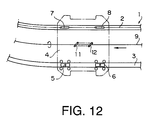
endless track 1. Theendless track 1 includes twostraight segments curved segments track 1 is formed by a pair ofendless rails track 1 to carry loads from the loading station C to the unloading station D. Eachcarriage 4 has fourwheels outer wheels outer rail 3 and the twoinner wheels inner rail 2. Generally, theouter rail 3 is used as a reference rail. Referring now to Figure 12, apropulsion shaft 9 extends between therails drive wheels carriage 4 rotate as thepropulsion shaft 9 rotates, and the' rotation of thedrive wheels carriage 4. - Referring back to Figure 13, the collision avoidance between the
carriages 4A-4D is the requisite for a safety automatic loading and unloading operation. For this purpose, a sensor for detecting a preceding carriage may be employed. Generally, the sensor mounting position is the carriage itself and an optical sensor unit (a pair of light emitting element and a light detector) is used. - As illustrated in Figure 13, a
light emitting element 13 is mounted on the back of each carriage and alight detector 14 is mounted on the front of the same such that when a plurality of carriages move in line on a single track, as shown in Figure 13, thedetector 14 of a carriage can detect a light P emitted from a preceding carriage. However, the conventionallight emitting sensor 13 emits the light P straight or in a very small angle. Therefore, thecarriage 4D can always receive the light from the precedingcarriage 4C since these carriages are in thestraight line 1b whereas thecarriage 4B cannot always receive the light from the precedingcarriage 4A since these twocarriages corner section 1a. Thecarriage 4B can detect the light P from the precedingcarriage 4A only when thecarriage 4B reaches in the vicinity of thecarriage 4A. As a result, when thesensor 14 of thecarriage 4B detects the optical signal P from thecarriage 4A, the distance between the twocarriages corner 1a is reduced to save the space, the collision possibility of thecarriage 4B against thecarriage 4A increases. - To prevent the collision of the carriages around the
corner 1a, conventionally thecarriage 4B is stopped at the entrance of thecorner 1a (as indicated by (B) or the location ofcarriage 4C) when the precedingcarriage 4A is at the exit of thecorner 1a. This means that there is no carriage in thecorner 1a when the precedingcarriage 4A is at the corner exit, or the interval between thecarriages - An object of the present invention is to provide a carriage collision avoidance system which can eliminate the above-mentioned problems.
- According to one aspect of the present invention, there is provided a system for preventing the collision of carriages moving in series on a track, the track including in turn a first straight section, a corner section and a second straight section, a light emitting element being mounted on a predetermined position of a rear half of each carriage for emitting a light backward, a first light detecting element being mounted on a predetermined position of a front half of each carriage for detecting a light emitted from the light emitting element of a preceding carriage for carriages, a plurality of carriages moving in series on a track, the track including in turn a first straight section, a corner section and a second straight section, a light emitting element being mounted on a predetermined position of a rear half of each carriage for emitting a light backward, a first light detecting element being mounted on a predetermined position of a front half of each carriage for detecting a light emitted from the light emitting element of a preceding carriage, and a controller being provided for decelerating a carriage when the first light detecting element of the carriage detects the light emitted from the preceding carriage, characterized in that the light emitting element emits the light at a first angle when the carriage moves in the straight sections whereas the light emitting element emits the light at a second angle larger than the first angle when the carriage moves in the corner section.
- The second angle is preferably between 150 and 180 degrees.
- Since the light emitting element emits the light in a wide angle (e.g., 150-180 degrees), the following carriage can detects the light even when it is moving in the corner section. Therefore, the collision of the carriages is prevented at the corner section.
- A first magnetic tape may be attached along at least part of the first straight section of the track and a second magnetic tape may be attached along the corner section and at least part of the second straight section of the track. Further, a magnetic sensor may be mounted on each carriage for detecting and distinguishing the first and second magnetic tapes. In such a system, the controller may decelerate the carriage when the magnetic sensor of the carriage detects the first magnetic tape and the controller may let the light emitting element emit the light at the second angle when the magnetic sensor of the carriage detects the second magnetic tape.
- Carriage stopping means may be provided to stop a carriage in the corner section when a preceding carriage exits around the exit of the corner section and to stop the carriage around the entrance of the corner section when the preceding carriage exits in the corner section.
- This improves the transfer efficiency since the carriage is not stopped at the entrance of the corner but stopped at the mid point of the corner when a preceding carriage exits at the exit of the corner.
- The carriage emits the light backward in a narrow angle (first angle) when it moves in the straight section, like a conventional system.
- The carriage stop means may include a first position sensor mounted on each carriage, a first element mounted on the track at a mid point of the corner section and a second element mounted on the track at the entrance of the corner. The carriage stop means may decelerate the carriage after the first position sensor detects the first element if a preceding carriage exits around the exit of the corner section in order to stop the carriage in the corner. Further, the carriage stop means may decelerate the carriage after the first position sensor detects the second element if the preceding carriage exits in the corner in order to stop the carriage around the entrance of the corner. The carriage stop means may include a second position sensor mounted on each carriage, the first and second position sensors may be spaced from each other in a moving direction of the carriage such that the lengths of the first and second elements are substantially the same as the distance of the first and second position sensors respectively. In such a case, the carriage stop means may stop the carriage when the first and second position sensors simultaneously detect the first or second element.
- The carriage may have a first wheel which rolls on the track and the first light detecting element may be mounted on the first wheel.
- Figure 1
- shows a plan view of automatic loading system including several carriages provided with novel light emitting elements according to the present invention;
- Figure 2
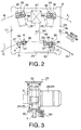
- is an enlarged plan view of carriage in the corner section of Figure 1;
- Figure 3
- is an enlarged lateral view of drive wheel of Figure 2;
- Figure 4
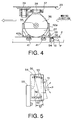
- is a front view of rear free wheel of Figure 2;
- Figure 5
- is a plan view showing the installation of position sensor of Figure 4;
- Figure 6
- is a front view of front free wheel of Figure 2;
- Figure 7
- illustrates a position sensor and a magnetic sensor of Figure 2;
- Figure 8
- shows how a carriage is stopped at a mid point of the corner of a track when a preceding carriage exits at the exit of the corner;
- Figure 9
- shows how a carriage is stopped at the entrance of the corner of the track when the preceding carriage exits at the mid point of the corner;
- Figure 10
- shows a situation similar to Figure 8 in another embodiment of the present invention;
- Figure 11
- shows a situation similar to Figure 9 in another embodiment of the present invention;
- Figure 12
- is a plan view showing a conventional carriage; and
- Figure 13
- shows a plan view of automatic loading system including several carriages provided with conventional light emitting elements.
- Referring to Figure 1, a plurality of
loading conveyors 21 and unloadingconveyors 22 are provided along atrack 1. Thetrack 1 has a loop shape, like the one as illustrated in Figure 13, and a number ofcarriages 23 move on thetrack 1. Loads are moved on theloading conveyors 21 from the left side of Figure 1 and unloaded on thecarriages 23. Thecarriages 23 carry the loads to theconveyors 22 on the other side. Thetrack 1 includes parallel inner andouter rails track 1 is comprised of a firststraight section 1b, a first rounded section (corner section) 1a and a secondstraight section 1c. - Referring to Figure 2, each
carriage 4 has twoinner wheels outer wheels inner wheels outer wheels guide rollers 33 and each pair ofguide rollers 33 hold theouter rail 3. Likewise, eachfree wheel guide rollers 41 and each pair ofguide rollers 41 hold theinner rail 2. Each drive wheel 24 (25) has ashaft 32 so that it can rotate about the center of theshaft 32. Likewise, eachfree wheel shaft 39 so that it can rotate about the center of theshaft 39. The frontfree wheel 26 is provided with a lightreceiving emitting element 52 which detects a light P coming from a preceding carriage. The rearfree wheel 27 is provided with alight emitting element 51 which sends a light P toward a following carriage.Motors drive wheels Numeral 57 designates a controller and 37 designates an arm, both of which will be explained later. - Referring to Figure 3, the drive wheel 24 (or 25) is supported by a
support member 31 extending from thecarriage 23. Therotatable shaft 32 extends through thesupport member 31. The motor 28 (or 29) is powered from asource 34. Each pair ofguide rollers 33 hold therail 3. - Two
free wheels wheel 27 will be only explained. Referring to Figure 4, thefree wheel 27 is supported under thecarriage 23 so as to be rotatable on therail 2. Acenter shaft 35 of thefree wheel 27 is supported by asupport member 36 and thesupport member 36 is supported by thearm 37 at its top. Thearm 37 holds theswing shaft 39 via a bearing so as to allow thesupport member 36 to rotate about the center axis of theshaft 39. One end of thearm 37 is supported by a fixedshaft 38 extending downward from thecarriage 23 such that thearm 37 can rotate about theshaft 38. Thesupport member 36 has a triangle shape as viewed from a direction vertical to the track 1 (just as illustrated in Figure 4), and L-shapedflanges guide rollers 41 are mounted on the ends of theflanges guide rollers 41 rotate along the lateral surface of therail 2. Thelight emitting element 51 is mounted on abracket 54 fixed anextension 53 attached to therear flange 42a. Therefore, thelight emitting element 51 is always directed in a tangential direction with respect to thetrack 1. Likewise, thelight receiving element 52 is always directed in a tangential direction with respect to thetrack 1. - Referring now to Figure 5, the
bracket 54 has a pair of arc-shapedelongated slots 55. Twobolts 56 which extend upward from thelight emitting element 51 engage theseslots 55 so that the position of thelight emitting element 51 is adjustable. Likewise, the slight positional adjustment of thelight receiving element 52 is also possible (not shown). - As illustrated in Figure 1, the
light emitting element 51 is mounted on the rearinner wheel 27 and emits the light P a predetermined distance in a wide angle (for example, 3 meters with 150-180 degrees), and thelight receiving element 52 is mounted on the frontinner wheel 26 to receive the light P from the preceding carriage. Thelight emitting element 51 may be an infrared beam emitting diode. - Referring back to Figure 2, when the
light receiving element 52 detects the light from the proceeding carriage, a detection signal is sent to thecontroller 57 via asignal line 87. Then, thecontroller 57 sends signals ("deceleration command") to thedrive wheels lines drive wheels carriage 23 can stop immediately upon receiving a "stop command" from thecontroller 57. After receiving the deceleration command, therefore, thecarriage 23 move very slowly until it receives the stop command. - Next, a situation where the stop command is issued will be explained. Means for stopping the carriage includes two detecting elements and three to-be-detected elements. Each to-be-detected element is a solid light interrupting plate in this embodiment. Referring to Figure 1, a first to-be-detected element (reflection plate) 62 is fixed at the entrance of the
corner 1a (or the end of the firststraight section 1b), asecond plate 63 is fixed at a three-quarter position of thecorner 1a and athird plate 64 is fixed at the exit of thecorner 1a (or the entrance of the secondstraight section 1c). Referring to Figure 6, the two detecting elements aresensors first position sensor 65 is mounted on thefront support member 42b of the frontfree wheel 26 and thesecond position sensor 66 is mounted on therear support member 42a of the frontfree wheel 26, respectively. Each position sensor (optical sensor) has a laid U-shape and emits a vertical light Q between two free ends of the U shape. When the light Q is interrupted by the plate 62 (or 63 or 64) as illustrated in Figure 7, the position sensor 65 (or 66) sends a light-interruption signal to thecontroller 57. In this embodiment, each light interruption plate 62 (63 or 64) has a predetermined length along thetrack 1 and the distance between theposition sensors position sensors first position sensor 65 is interrupted by theplate 62, for example, thefirst position sensor 65 sends a signal to thecontroller 57 by way of line 87 (Figure 2). Then, thecontroller 57 sends a deceleration signal to themotors drive wheels plate 62. - Referring to Figure 6, another
bracket 68 is attached to thesupport member 36 and arotary encoder 67 is mounted on the free end of thebracket 68. Therotary encoder 67 rolls along the inner lateral surface of therail 2 to measure the traveling distance of thecarriage 23. Therotary encoder 67 is used to set the timing of the braking. - It should be noted that the
plates optical sensors - Referring to Figure 7, a
member 71 is supported by thesupport member 42a and amagnetic sensor 72 is mounted on themember 71. Themagnetic sensor 72 can distinguish the kind ofmagnetic tapes inner rail 2. As illustrated in Figure 1, a firstmagnetic tape 73 is attached along part of the firststraight section 1b (as indicated by the broken line) and a secondmagnetic tape 74 is attached along thecorner section 1a and part of the secondstraight section 1c (as indicated by the single-dot line). The firstmagnetic tape 73 has an S polarity and the secondmagnetic tape 74 has an N polarity. When themagnetic sensor 72 detects that the carriage moves along the firstmagnetic tape 73, the speed of the carriage is decelerated. On the other hand, when themagnetic sensor 72 detects that the carriage moves along the secondmagnetic tape 74 or that the carriage enters thecorner section 1a, then thelight emitting element 51 of the carriage starts emitting the light P in the wide angle. - When the carriage moves in the
straight section light emitting element 51 does not have to emit the light in the wide angle. More specifically, if thelight emitting element 51 always emits the light P in the wide angle, the light P emitted from thestraight section 1b, for example, may affect the traveling of other carriages moving on the otherstraight section 1c. Therefore, thelight emitting element 51 emits the light P only when it moves along the secondmagnetic tape 74. - Referring to Figure 1, a plurality of loading and unloading
conveyors track 1, and thecarriages 23 are stopped at predetermined loading and unloadingconveyors interruption plate 75 is provided for each loading and unloadingconveyors carriage 23 is reduced when it approaches the predetermined station. In this embodiment, the speed reduction starts when thecarriage 23 reaches a predetermined position which is measured and determined byencoder 67. - As mentioned earlier, the
light emitting element 51 only emits the light P when thecarriage 23 moves along the second pate 74 (or in thecorner 1a of the track 1). When thecarriage 23 moves in thestraight section other sensors light emitting element 51 and thelight receiving element 52. These sensors emit lights in a narrow angle. Therefore, conventional light emitting elements may be employed. - Figure 8 illustrates how a
carriage 23B is stopped at a mid point in thecorner 1a when a precedingcarriage 23A is at the exit of thecorner 1a. The precedingcarriage 23A emits the light P backward in a wide angle so that thecarriage 23B can detects the light P when thecarriage 23B proceeds in thecorner section 1a. (Of course, thecarriage 23B is already decelerated when the firstmagnetic tape 73 is detected.) Upon detecting the light P, thecarriage 23B is further decelerated. After that, when the twoposition sensors corner 1a, thecarriage 23B stops at a mid point in thecorner 1a, as indicated by "STOP". As explained earlier, after thefirst position sensor 65 of thecarriage 23B detects theplate 63, thecarriage 23B is decelerated to be stopped at a predetermined position where both the first andsecond position sensors carriage 23B detect thesame plate 63. If the carriage passes over theplate 63, the carriage is moved backward. It should be noted that the stop position is not limited to the mid point of thecorner 1a as long as a safety distance is insured between the front of thecarriage 23B and the tail of the precedingcarriage 23A. - Referring to Figure 9, illustrated is a case where a
carriage 23C is stopped at the entrance of thecorner 1a when thecarriage 23B exists at the mid point of thecorner 1a. Thecarriage 23B emits the light P in a fan or oval shape, and when the followingcarriage 23C enters this oval area, as indicated by "ON", thelight detecting element 52 of thecarriage 23C detects the light P so that thecontroller 57 sends a deceleration command to thecarriage 23C. This speed reduction starts while thecarriage 23C is moving on thestraight stack 1b. After that, thefirst position sensor 65 detects the first plate 62 (Figure 1) which is located at the entrance of thecorner 1a, and then thecontroller 57 sends a stop command to thecarriage 23C. In the same manner as explained with Figure 8, thecarriage 23C stops at a predetermined position (at the entrance of thecorner 1a), as indicated by "STOP". It should be noted that the stop position is not limited to the entrance of thecorner 1a, but may be a little closer to the position of thecarriage 23B as long as a safety distance is insured between thecarriages - Therefore, the collision of the carriages around the
corner 1a as well as on thestraight sections corner 1a when the precedingcarriage 23A exists at the exit of thecorner 1a. - Referring back to Figure 8, if a floor plate (shaded member) 79 is provided to allow an operator to walk thereon or step into the
track 1, pedestals (not shown) of thefloor 79 may become obstacles to the light P, since thelight emitting element 51 emits the light P under thefloor 79. The reflection by the floor pedestals affect the carriage movement control. To prevent this problem, referring to now Figure 10, twolight detectors single light detector 52. Thefirst light detector 52a is attached to the inner side (lateral portion) of the carriage above thefloor 79 and the secondlight detector 52b is attached to the front of the carriage above thefloor 79. When the precedingcarriage 23A is at the exit of thecorner 1a and thecarriage 23B reaches the entrance of thecorner 1a, thefirst light detector 52a detects the light P emitted from the precedingcarriage 23A and thecarriage 23B starts decelerating. Then, theposition sensors 65 and 66 (Figure 6) detect theplate 63 and thecarriage 23B stops at the mid point of thecorner 1a as indicated by "STOP". If thecarriage 23B is stopped at the mid point of thecorner 1a, as shown in Figure 11, the secondlight detector 52b of the followingcarriage 23C detects the light P emitted from thecarriage 23B as thecarriage 23C approaches thecarriages 23B. Upon detecting the light P, thecarriage 23C is decelerated and eventually stopped at the entrance of thecorner 1a as indicated by "STOP" after the position sensors of thecarriage 23C detect the plate 62 (Figure 1).
Claims (9)
- A collision avoidance system for carriages (23) moving in series on a track (1), the track (1) including in turn a first straight section (1b), a corner section (1a) and a second straight section (1c), a light emitting element (51) being mounted on a predetermined position of a rear half of each carriage (23) for emitting a light (P) backward, a first light detecting element (52) being mounted on a predetermined position of a front half of each carriage (23) for detecting a light (P) emitted from the light emitting element (51) of a preceding carriage, and a controller (57) being provided for decelerating a carriage (23) when the first light detecting element (52) of the carriage detects the light (P) emitted from the preceding carriage, characterized in that the light emitting element (51) emits the light (P) at a first angle when the carriage moves in the straight sections (1b, 1c) whereas the light emitting element (51) emits the light (P) at a second angle larger than the first angle when the carriage moves in the corner section (1b).
- The collision avoidance system of claim 1, characterized in that a first magnetic tape is attached along at least part of the first straight section of the track, a second magnetic tape is attached along the corner section and at least part of the second straight section of the track, a magnetic sensor is mounted on each carriage for detecting and distinguishing the first and second magnetic tapes, and the controller decelerates the carriage when the magnetic sensor of the carriage detects the first magnetic tape and the controller lets the light emitting element emit the light at the second angle when the magnetic sensor of the carriage detects the second magnetic tape.
- The collision avoidance system of claim 1 or 2, characterized in that carriage stopping means is provided to stop a carriage in the corner section when a preceding carriage exits around the exit of the corner section and to stop the carriage around the entrance of the corner section when the preceding carriage exits in the corner section.
- The collision avoidance system of claim 3, characterized in that the carriage stop means includes a first position sensor mounted on each carriage, a first element mounted on the track at a mid point of the corner section and a second element mounted on the track at the entrance of the corner, the carriage stop means decelerates the carriage after the first position sensor detects the first element if a preceding carriage exits around the exit of the corner section in order to stop the carriage in the corner, and the carriage stop means decelerates the carriage after the first position sensor detects the second element if the preceding carriage exits in the corner in order to stop the carriage around the entrance of the corner.
- The collision avoidance system of claim 4, characterized in that the carriage stop means includes a second position sensor mounted on each carriage, the first and second position sensors are spaced from each other in a moving direction of the carriage, the lengths of the first and second elements are substantially the same as the distance of the first and second position sensors respectively, and the carriage stop means stops the carriage when the first and second position sensors simultaneously detect the first or second element.
- The collision avoidance system of anyone of foregoing claims, characterized in that the second angle is between 150 and 180 degrees.
- The collision avoidance system of anyone of foregoing claims, characterized in that the carriage has a first wheel which rolls on the track and the first light detecting element is mounted on the first wheel.
- The collision avoidance system of claim 7, characterized in that the carriage has a second wheel which rolls on the track behind the first wheel and the second light detecting element is mounted on the second wheel.
- The collision avoidance system of anyone of claims 1 to 6, characterized in that the first light detecting element is mounted on a front portion of the carriage and a second light detecting element is mounted on a lateral portion of the carriage.
Applications Claiming Priority (2)
| Application Number | Priority Date | Filing Date | Title |
|---|---|---|---|
| JP4347392A JP3052539B2 (en) | 1992-02-28 | 1992-02-28 | Anti-collision device for tracked bogies |
| JP43473/92 | 1992-02-28 |
Publications (2)
| Publication Number | Publication Date |
|---|---|
| EP0557962A1 true EP0557962A1 (en) | 1993-09-01 |
| EP0557962B1 EP0557962B1 (en) | 1995-11-02 |
Family
ID=12664694
Family Applications (1)
| Application Number | Title | Priority Date | Filing Date |
|---|---|---|---|
| EP19930102865 Expired - Lifetime EP0557962B1 (en) | 1992-02-28 | 1993-02-24 | Collision avoidance system for carriages |
Country Status (2)
| Country | Link |
|---|---|
| EP (1) | EP0557962B1 (en) |
| JP (1) | JP3052539B2 (en) |
Cited By (2)
| Publication number | Priority date | Publication date | Assignee | Title |
|---|---|---|---|---|
| US5758847A (en) * | 1995-08-18 | 1998-06-02 | Bayerische Motoren Werke Aktiengesellschaft | Control device for overhead conveyor |
| US9793147B2 (en) | 2015-09-09 | 2017-10-17 | Samsung Electronics Co., Ltd. | Transporting system and transporting unit included therein |
Families Citing this family (1)
| Publication number | Priority date | Publication date | Assignee | Title |
|---|---|---|---|---|
| JPH07186940A (en) * | 1993-12-28 | 1995-07-25 | Kito Corp | Carriage truck |
Citations (5)
| Publication number | Priority date | Publication date | Assignee | Title |
|---|---|---|---|---|
| US4158841A (en) * | 1976-05-26 | 1979-06-19 | Daimler-Benz Aktiengesellschaft | Method and apparatus for the control of the safety distance of a vehicle relative to preceding vehicles |
| EP0052263A1 (en) * | 1980-11-14 | 1982-05-26 | Inventio Ag | Device to keep track-bound vehicles at a distance from one another |
| GB2222710A (en) * | 1988-09-09 | 1990-03-14 | John Home | Vehicle monitoring systems |
| US4920520A (en) * | 1987-09-08 | 1990-04-24 | Ibp Pietzsch Gmbh | Method of and a device for safeguarding a vehicle or machinery movable in space |
| EP0466217A2 (en) * | 1990-07-10 | 1992-01-15 | Daifuku Co., Ltd. | Equipment for transporting a load |
-
1992
- 1992-02-28 JP JP4347392A patent/JP3052539B2/en not_active Expired - Lifetime
-
1993
- 1993-02-24 EP EP19930102865 patent/EP0557962B1/en not_active Expired - Lifetime
Patent Citations (5)
| Publication number | Priority date | Publication date | Assignee | Title |
|---|---|---|---|---|
| US4158841A (en) * | 1976-05-26 | 1979-06-19 | Daimler-Benz Aktiengesellschaft | Method and apparatus for the control of the safety distance of a vehicle relative to preceding vehicles |
| EP0052263A1 (en) * | 1980-11-14 | 1982-05-26 | Inventio Ag | Device to keep track-bound vehicles at a distance from one another |
| US4920520A (en) * | 1987-09-08 | 1990-04-24 | Ibp Pietzsch Gmbh | Method of and a device for safeguarding a vehicle or machinery movable in space |
| GB2222710A (en) * | 1988-09-09 | 1990-03-14 | John Home | Vehicle monitoring systems |
| EP0466217A2 (en) * | 1990-07-10 | 1992-01-15 | Daifuku Co., Ltd. | Equipment for transporting a load |
Cited By (3)
| Publication number | Priority date | Publication date | Assignee | Title |
|---|---|---|---|---|
| US5758847A (en) * | 1995-08-18 | 1998-06-02 | Bayerische Motoren Werke Aktiengesellschaft | Control device for overhead conveyor |
| US9793147B2 (en) | 2015-09-09 | 2017-10-17 | Samsung Electronics Co., Ltd. | Transporting system and transporting unit included therein |
| US10056280B2 (en) | 2015-09-09 | 2018-08-21 | Samsung Electronics Co., Ltd. | Transporting system and transporting unit included therein |
Also Published As
| Publication number | Publication date |
|---|---|
| JPH05238380A (en) | 1993-09-17 |
| EP0557962B1 (en) | 1995-11-02 |
| JP3052539B2 (en) | 2000-06-12 |
Similar Documents
| Publication | Publication Date | Title |
|---|---|---|
| JP2844073B2 (en) | Carrier self-propelled conveyor | |
| JP4151108B2 (en) | Anti-collision device for automated guided vehicles | |
| EP0557962B1 (en) | Collision avoidance system for carriages | |
| JP2000214928A (en) | Automated guided vehicle | |
| JP3201173B2 (en) | Automatic traveling cart | |
| JP4547785B2 (en) | Moving shelf equipment | |
| JP3219138B2 (en) | Tracked bogie system | |
| JP2910245B2 (en) | Driverless vehicle safety devices | |
| KR0168701B1 (en) | Method for controlling carriage running speed in separation of conveyor | |
| JP3620144B2 (en) | Track control device for tracked carriage | |
| JP3267056B2 (en) | Traveling control method and device for tracked bogie | |
| JP2553912B2 (en) | Load transfer equipment | |
| JP2523305Y2 (en) | Automatic distance control system for carriers | |
| JPH08337303A (en) | Conveying dolly system | |
| JP2957545B1 (en) | Automatic transfer cart | |
| JP2001216024A (en) | Baggage carrying facility | |
| JP4023266B2 (en) | Traveling device for traveling body | |
| JP2001249718A (en) | Collision preventing device for carrier in rail carrying device | |
| KR20120018990A (en) | Cargo-working apparatus | |
| JPH068102Y2 (en) | Carrier | |
| JP2800449B2 (en) | Load transfer equipment | |
| JP3311603B2 (en) | Sorting device and sorting method | |
| JPH0219483B2 (en) | ||
| JPH09216704A (en) | Stop device of unmanned carriage | |
| KR20210144709A (en) | Object detection system, transport cart, and object detection device |
Legal Events
| Date | Code | Title | Description |
|---|---|---|---|
| PUAI | Public reference made under article 153(3) epc to a published international application that has entered the european phase |
Free format text: ORIGINAL CODE: 0009012 |
|
| AK | Designated contracting states |
Kind code of ref document: A1 Designated state(s): AT BE CH DE DK ES FR GB GR IE IT LI LU MC NL PT SE |
|
| RBV | Designated contracting states (corrected) |
Designated state(s): BE FR LU MC NL PT SE |
|
| 17P | Request for examination filed |
Effective date: 19931008 |
|
| REG | Reference to a national code |
Ref country code: DE Ref legal event code: 8566 |
|
| RBV | Designated contracting states (corrected) |
Designated state(s): BE FR NL |
|
| 17Q | First examination report despatched |
Effective date: 19950217 |
|
| GRAA | (expected) grant |
Free format text: ORIGINAL CODE: 0009210 |
|
| AK | Designated contracting states |
Kind code of ref document: B1 Designated state(s): BE FR NL |
|
| ET | Fr: translation filed | ||
| PLBE | No opposition filed within time limit |
Free format text: ORIGINAL CODE: 0009261 |
|
| STAA | Information on the status of an ep patent application or granted ep patent |
Free format text: STATUS: NO OPPOSITION FILED WITHIN TIME LIMIT |
|
| 26N | No opposition filed | ||
| PGFP | Annual fee paid to national office [announced via postgrant information from national office to epo] |
Ref country code: FR Payment date: 20120221 Year of fee payment: 20 |
|
| PGFP | Annual fee paid to national office [announced via postgrant information from national office to epo] |
Ref country code: BE Payment date: 20120214 Year of fee payment: 20 |
|
| PGFP | Annual fee paid to national office [announced via postgrant information from national office to epo] |
Ref country code: NL Payment date: 20120221 Year of fee payment: 20 |
|
| BE20 | Be: patent expired |
Owner name: *ISHIKAWAJIMA-HARIMA HEAVY INDUSTRIES CO. LTD Effective date: 20130224 |
|
| REG | Reference to a national code |
Ref country code: NL Ref legal event code: V4 Effective date: 20130224 |