EP0557947B1 - Horizontally- and vertically-working viscous vibration damper - Google Patents
Horizontally- and vertically-working viscous vibration damper Download PDFInfo
- Publication number
- EP0557947B1 EP0557947B1 EP93102842A EP93102842A EP0557947B1 EP 0557947 B1 EP0557947 B1 EP 0557947B1 EP 93102842 A EP93102842 A EP 93102842A EP 93102842 A EP93102842 A EP 93102842A EP 0557947 B1 EP0557947 B1 EP 0557947B1
- Authority
- EP
- European Patent Office
- Prior art keywords
- annular
- disk
- damper
- disks
- strut
- Prior art date
- Legal status (The legal status is an assumption and is not a legal conclusion. Google has not performed a legal analysis and makes no representation as to the accuracy of the status listed.)
- Expired - Lifetime
Links
Images

Classifications
-
- F—MECHANICAL ENGINEERING; LIGHTING; HEATING; WEAPONS; BLASTING
- F16—ENGINEERING ELEMENTS AND UNITS; GENERAL MEASURES FOR PRODUCING AND MAINTAINING EFFECTIVE FUNCTIONING OF MACHINES OR INSTALLATIONS; THERMAL INSULATION IN GENERAL
- F16F—SPRINGS; SHOCK-ABSORBERS; MEANS FOR DAMPING VIBRATION
- F16F9/00—Springs, vibration-dampers, shock-absorbers, or similarly-constructed movement-dampers using a fluid or the equivalent as damping medium
- F16F9/10—Springs, vibration-dampers, shock-absorbers, or similarly-constructed movement-dampers using a fluid or the equivalent as damping medium using liquid only; using a fluid of which the nature is immaterial
- F16F9/103—Devices with one or more members moving linearly to and fro in chambers, any throttling effect being immaterial, i.e. damping by viscous shear effect only
-
- E—FIXED CONSTRUCTIONS
- E04—BUILDING
- E04H—BUILDINGS OR LIKE STRUCTURES FOR PARTICULAR PURPOSES; SWIMMING OR SPLASH BATHS OR POOLS; MASTS; FENCING; TENTS OR CANOPIES, IN GENERAL
- E04H9/00—Buildings, groups of buildings or shelters adapted to withstand or provide protection against abnormal external influences, e.g. war-like action, earthquake or extreme climate
- E04H9/02—Buildings, groups of buildings or shelters adapted to withstand or provide protection against abnormal external influences, e.g. war-like action, earthquake or extreme climate withstanding earthquake or sinking of ground
- E04H9/021—Bearing, supporting or connecting constructions specially adapted for such buildings
- E04H9/0235—Anti-seismic devices with hydraulic or pneumatic damping
Definitions
- the invention relates to a horizontally and vertically acting vibration damper according to the preamble of claim 1.
- Viscous dampers which consist of a mostly cylindrical housing which is filled with a viscous or viscoelastic medium, and a likewise usually cylindrical damper plunger which is immersed in the damping medium.
- One part - usually the damper stamp - is connected to the object to be mechanically damped, the other part is connected to a fixed point.
- Damping forces are generated in such vibration dampers with each relative movement between the damper housing and damper plunger; the magnitude of this force is generally dependent on the direction of the movement.
- the ratio of the forces in the case of pure vertical movement (movement in the direction of the cylinder axis of the housing or stamp) and pure horizontal movement can be varied within certain limits by suitable dimensions of the housing and stamp.
- vibration dampers are used in mechanical engineering for damping vibratory systems. It can These are, for example, machines or machine parts, sensitive vibration-isolated measuring devices, pipelines or complete buildings.
- two ring disks are attached to the damper ram at an axial distance from one another and two further ring disks, for example, are attached to the cylindrical peripheral wall of the housing at an axial distance from one another, one above the upper damper ram ring disk, the other between the two Damper ring washers.
- damping forces are generated when the individual annular disks move parallel to one another during horizontal movements. The horizontal path is limited by the play of the damper stamp ring washers to the damper housing or the play between the damper stamp and the ring washers attached to the housing.
- a major disadvantage of the known vibration dampers is that long distances - as are required especially in the horizontal direction when used in earthquake protection systems - are practically not possible.
- the distances must be chosen so large in the case of the known construction that the predetermined movements are made possible.
- the damping force drops with increasing distances, so that effective vibration dampers then have very large dimensions.
- the invention has for its object to provide a damper of the type specified that allows relatively large relative movements, especially in the horizontal direction, with relatively small dimensions.
- the arrangement of drivers on the outer edge of the washers is recommended, in particular in the form of ring flanges.
- the ring disks can have ring flanges of different diameters and can be inserted into one another in the manner of plates.
- a particularly advantageous embodiment consists in that a single washer is fastened to the damper ram and a group of any number of further washers is arranged above and below it; seen from the ring disk of the damper plunger are provided on this ring flange from the second further ring disk in such a way that the ring flanges of the two ring disk groups are axially oppositely aligned. Seen from the ring washers, the ring flanges of the two groups of ring washers should be aligned with each other.
- annular flange which is firmly connected to the peripheral wall and which limits the vertical movements of the annular disk group and the damper plunger to a predetermined maximum value can also be provided above the upper annular disk group and below the lower annular disk group.
- the lowest ring disk can be arranged lying on the base plate of the damper housing, this design is preferably used when a particularly low overall height is required.
- two ring disks can be arranged fastened to the damper ram at an axial distance from one another and the two groups of further ring disks can be arranged between them.
- the largest ring disk of both disk groups can belong to both groups, i. H. there is now a single, correspondingly large ring disk, which is then expediently assigned a double-sided ring flange.
- Another particularly flat embodiment can be achieved in that at least two further ring disks with the special diameter ratios follow the ring disk assigned to the damper ram.
- the axial mutual assignment of the ring disks can be very narrow and the horizontal mobility can be very large at the same time.
- the vertical movement of all panes is strictly limited only by the overall height of the housing.
- the embodiment described above allows a further development with additional ring disks in which a group of further ring disks are arranged on one side of the ring disk of the damper stamp and a group of additional ring disks are arranged on the other side of the ring disk of the damper stamp, with a correspondingly large size Damping effect in the vertical and in the horizontal direction.
- the ring disks behave practically like a telescope because of their close mutual association.
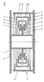
- the damper consists of an outer damper housing 1, with a lower base plate 2 and a preferably cylindrical circumferential wall 3, and a damper ram 4 protruding into the damper housing 1 from above, which is attached to a cover plate 5.
- An essentially central annular disk 6 is connected to the damper plunger 4 and is surrounded by an upper and a lower group, each of a plurality of annular disks.
- the upper group of disks comprises a flat washer 7 and two washers 8 and 9, which are provided on their outer peripheral edge with a driver in the form of an annular flange 10 and 15, respectively.
- an annular disk 11 which is attached to the upper edge of the peripheral wall 3.
- the lower group of disks comprises a flat washer 12, two washers 13 and 14, which are equipped with an annular flange 10 and 15, and finally an washer 16, which is arranged on the bottom region of the peripheral wall 3.
- the base plate 2 serves as a fastening means or fixed point.
- the damper housing 1 is filled with viscous damping medium.
- the damper plunger 4 is connected to a vibrating object (not shown) via the cover plate 5.
- the washers 7, 8 and 9 of the upper disk group and the washers 12, 13 and 14 of the lower disk group can be moved freely.
- the washers 8 and 9 and 13 and 14 each have such a diameter that two washers 8 and 9 or 13 and 14 are arranged in a plate-like manner.
- the ring flanges 10 and 15 of the ring disks 8, 9 and 13, 14 have the task of a driver.
- the distance between the damper plunger 4 and the peripheral wall 3 is divided into smaller displacements of the individual ring disks.
- all the ring disks move simultaneously so that the total path corresponds to the relative path between the damper ram 4 and the peripheral wall 3.
- very low-viscosity damping media there is a telescopic movement.
- the forces can reach similar orders of magnitude if the damper plunger 4 is moved in the vertical direction. These forces are mainly generated by the displacement of the damping medium between the washers 6, 7, 8, 9 and 11. In contrast to horizontal movement, the vertical movement is restricted by the special design. When the damper plunger 4 moves downward, the lowest point is reached when the ring disks 6 and 12, 12 and 13, 13 and 14 and 14 and 16 lie in pairs. The same applies to the upward movement of the damper plunger 4.
- each ring flange 10 or 15 of the movable ring disks 8, 9 or 13, 14 must be such that it is longer than the distance between the facing surfaces of the ring disks 11 and 16 fixed on the peripheral wall 3 reduced by the axial Thicknesses of all the ring disks located between the ring disks 11 and 16, i.e. the ring disks 6, 7, 8, 9 and 12, 13, 14.
- Such a dimensioning of the axial extent of the ring flanges 10 and 15 ensures permanent coupling of all the ring disks and a disintegration of the for example, the disc group consisting of the ring discs 6, 7, 8 and 9 or the group consisting of the ring discs 6, 12, 13, 14 prevented.
- the formation of an oblique position of the individual ring disks is prevented, which could lead to jamming, as a result of which, in the opposite direction, movement of the ring disks would be prevented.
- the embodiment according to FIG. 1 can be modified such that the annular disk 6 is not fixedly arranged on the damper ram 4, but maintains a radial distance from the damper ram 4 or is arranged with radial play to the damper ram 4.
- the difference compared to the embodiment of FIG. 1 is then that the washer 6 is vertically displaceably connected to the damper ram 4.
- This enables much larger vertical movements; however, the damping force is considerably lower than in the embodiment shown in FIG. 1. It is then practically achieved only by shearing the damping medium between the damper plunger 4 and the inner surfaces of the annular disks 6, 7, 8, 9 and 11 or 6, 12, 13, 14 and 16. If the damper plunger 4 is closed at its lower end, an additional displacement component in the vertical direction or a shear component during horizontal movement can be generated.
- This variant is particularly suitable for use in connection with earthquake protection systems, where the vertical movements usually do not require any noteworthy damping.
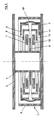
- Fig. 2 shows an embodiment which differs from that of Fig. 1 primarily in that the washers 11 and 16 are omitted. This embodiment is therefore very easy to manufacture.
- a bellows-shaped sleeve 40 is provided on the outer circumference of the two disk groups in such a way that both can only move apart from one another by a predetermined distance in the axial direction.
- the sleeve 40 is thus fastened to the uppermost and to the lowermost ring disks 9 and 14 and prevents these two disks from moving too far apart.
- the vertical damping effect in the embodiment according to FIG. 2 mainly results from the displacement of the damping medium.
- the vertical damping path is considerably larger than in the damper according to FIG. 1.
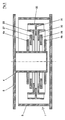
- each annular disk 6a, 6b is arranged at an axial distance from one another.
- two groups of several washers are provided.
- Each group comprises a flat washer 27 and 28, respectively, an washer 29 and 30, each with an outer ring flange, and finally a central washer 31, which belongs to both groups and is equipped with a double ring flange 32, which extends axially from the outer edge of the washer 31 Direction protrudes on opposite sides.
- the embodiment according to FIG. 3 is particularly suitable for large, vertically acting damping forces, namely for large movements. Since there are no annular disks 11 or 16 according to FIG. 1 in this embodiment, larger vertical movements are possible. With suitable dimensions, practically any vertical movements are possible, which are associated with a damping force that is generated mainly by the displacement of the damping medium on the upper and lower surfaces of the disk groups. In the horizontal direction, the procedure described above is obtained. While maintaining the damping effect in the vertical direction, the damping force for horizontal movements can be increased as desired if a plurality of disk packs consisting of annular disks 27, 29, 31, 30, 28 are provided. For each additional package, only one additional ring disk 6a or 6b may then be required.
- annular disc 6 is fixedly arranged on the damper ram 4, which is therefore movable both vertically and horizontally with the damper ram 4.
- this washer 6 is followed by a first further washer 7 and a further washer 8, each further washer having an outside diameter larger than the latter and an inside diameter smaller than the outside diameter of the latter with respect to the preceding ring disk.
- additional ring disks 8a and 7a follow, the same diameter ratios as just stated apply to these and their preceding ring disks.
- the smallest of the additional washers namely the washer 7a
- the washer 7a is not fixedly arranged on the damper plunger 4, but is associated with it with slight radial play.
- Such a radial play is otherwise provided on the outside of the annular disc 8 opposite the peripheral wall 3.
- the two radial games mentioned serve to move the damper plunger 4 together with the ring disks mentioned above in the vertical direction.
- a displacement of the damper plunger 4 from the right end position shown in FIG. 4 to the left causes the annular disks 6 and 7a to be displaced relative to the annular disks 7 and 8a or to the annular disk 8. This displacement is quasi a telescopic displacement.
- the damper can be equipped with a plurality of “large groups” of ring disks as described above, as can also be seen from FIG. 4.
- the smallest additional ring disk 7a of a first "large group” also forms the smallest further ring disk of the next "large group”;
- it therefore represents an equivalent to the washer 6 of the first "large group”, but without being fixed to the damper ram 4 at the same time.
- This embodiment is characterized by a particularly low overall height with regard to a disproportionately large damping effect in the vertical direction, while at the same time allowing relatively very large horizontal movements.
- the annular disk 6 can be arranged on the damper ram 4 with radial play, to achieve a specific damping characteristic.
- the disk groups shown in each case several times one above the other and equipping them with any number of ring disks in order to be able to realize greater damping forces.
- All embodiments are such a particularly compact construction, especially with a low overall height.
Description
Die Erfindung betrifft einen horizontal und vertikal wirkenden Schwingungsdämpfer gemäß Oberbegriff des Anspruchs 1.The invention relates to a horizontally and vertically acting vibration damper according to the preamble of
Bekannt sind viskose Dämpfer, die aus einem meist zylindrischen Gehäuse, das mit einem viskosen oder viskoelastischen Medium gefüllt ist, und einem ebenfalls meist zylindrischen Dämpferstempel bestehen, der in das Dämpfungsmedium eintaucht. Ein Teil - meistens der Dämpferstempel - ist mit dem mechanisch zu dämpfenden Objekt, das andere Teil mit einem ortsfesten Punkt verbunden.Viscous dampers are known which consist of a mostly cylindrical housing which is filled with a viscous or viscoelastic medium, and a likewise usually cylindrical damper plunger which is immersed in the damping medium. One part - usually the damper stamp - is connected to the object to be mechanically damped, the other part is connected to a fixed point.
Bei mechanischen Schwingungen des Objekts kommt es zu einer Relativbewegung zwischen Dämpfergehäuse und Dämpferstempel. Dabei wird die mechanische Energie des Gesamtsystems durch Scherungs- und Verdrängungsvorgänge im Dämpfungsmedium in Wärme umgewandelt. Die Dämpfungskraft wächst annähernd linear mit der Viskosität des Dämpfungsmediums und der Größe der relativ zueinander bewegten Scher- und Verdrängungsflächen. Sie wächst weiterhin mit kleiner werdenden Abständen zwischen diesen Flächen.When the object vibrates mechanically, there is a relative movement between the damper housing and the damper plunger. The mechanical energy of the overall system is converted into heat by shear and displacement processes in the damping medium. The damping force increases approximately linearly with the viscosity of the damping medium and the size of the shear and displacement surfaces that are moved relative to one another. It continues to grow with increasing distances between these areas.
Dämpfungskräfte werden bei derartigen Schwingungsdämpfern bei jeder Relativbewegung zwischen Dämpfergehäuse und Dämpferstempel erzeugt; die Größe dieser Kraft ist aber im allgemeinen abhängig von der Richtung der Bewegung. Das Verhältnis der Kräfte bei reiner Vertikalbewegung (Bewegung in Richtung der Zylinderachse des Gehäuses bzw. Stempels) und reiner Horizontalbewegung kann durch geeignete Abmessungen von Gehäuse und Stempel in gewissen Grenzen variiert werden.Damping forces are generated in such vibration dampers with each relative movement between the damper housing and damper plunger; the magnitude of this force is generally dependent on the direction of the movement. The ratio of the forces in the case of pure vertical movement (movement in the direction of the cylinder axis of the housing or stamp) and pure horizontal movement can be varied within certain limits by suitable dimensions of the housing and stamp.
Derartige Schwingungsdämpfer werden im Maschinenbau zur Dämpfung schwingungsfähiger Systeme eingesetzt. Dabei kann es sich z.B. um Maschinen oder Maschinenteile, empfindliche schwingungsisoliert aufgestellte Meßapparate, Rohrleitungen oder komplette Gebäude handeln.Such vibration dampers are used in mechanical engineering for damping vibratory systems. It can These are, for example, machines or machine parts, sensitive vibration-isolated measuring devices, pipelines or complete buildings.
Bei bekannten Dämpfern der eingangs bezeichneten Gattung sind am Dämpferstempel in axialem Abstand zueinander bspw. zwei Ringscheiben und an der zylinderischen Umlaufwand des Gehäuses in axialem Abstand zueinander bspw. zwei weitere Ringscheiben befestigt, die eine oberhalb der oberen Dämpferstempel-Ringscheibe, die andere zwischen den zwei Dämpferstempel-Ringscheiben. Bei dieser bekannten Konstruktion werden Dämpfungskräfte erzeugt, wenn sich die einzelnen Ringscheiben bei Horizontalbewegungen parallel aneinander vorbeibewegen. Der Horizontalweg ist begrenzt durch das Spiel der Dämpferstempel-Ringscheiben zum Dämpfergehäuse bzw. das Spiel zwischen dem Dämpferstempel und den am Gehäuse befestigten Ringscheiben.In known dampers of the type described in the introduction, two ring disks, for example, are attached to the damper ram at an axial distance from one another and two further ring disks, for example, are attached to the cylindrical peripheral wall of the housing at an axial distance from one another, one above the upper damper ram ring disk, the other between the two Damper ring washers. In this known construction, damping forces are generated when the individual annular disks move parallel to one another during horizontal movements. The horizontal path is limited by the play of the damper stamp ring washers to the damper housing or the play between the damper stamp and the ring washers attached to the housing.
Ein großer Nachteil der bekannten Schwingungsdämpfer liegt darin, daß große Wege - wie sie besonders in Horizontalrichtung beim Einsatz in Erdbebenschutzsystemen benötigt werden - praktisch nicht möglich sind. Hierzu müssen die Abstände im Falle der bekannten Konstruktion so groß gewählt werden, daß die vorgegebenen Bewegungen ermöglicht werden. Die Dämpfungskraft fällt aber mit wachsenden Abständen ab, so daß wirkungsvolle Schwingungsdämpfer dann sehr große Abmessungen aufweisen.A major disadvantage of the known vibration dampers is that long distances - as are required especially in the horizontal direction when used in earthquake protection systems - are practically not possible. For this purpose, the distances must be chosen so large in the case of the known construction that the predetermined movements are made possible. The damping force drops with increasing distances, so that effective vibration dampers then have very large dimensions.
Der Erfindung liegt die Aufgabe zugrunde, einen Dämpfer der eingangs angegebenen Gattung zu schaffen, der bei vergleichsweise kleinen Abmessungen vergleichsweise große Relativbewegungen, insbesondere in Horizontalrichtung, ermöglicht.The invention has for its object to provide a damper of the type specified that allows relatively large relative movements, especially in the horizontal direction, with relatively small dimensions.
Diese Aufgabe wird erfindungsgemäß durch die Merkmale des kennzeichnenden Teils des Anspruchs 1 gelöst.This object is achieved by the features of the characterizing part of
Durch diese Ausbildung, zu der bestimmte Durchmesserverhältnisse gehören und die beliebig viele weitere Ringscheiben aufweisen kann, ist nicht nur ein Dämpfer geschaffen, der vergleichsweise große Wege in Horizontalrichtung erlaubt, sondern auch in vergleichsweise kleinen räumlichen Abmessungen herstellbar ist, insbesondere mit vergleichsweise sehr niedriger Bauhöhe. Im übrigen läßt diese Ausbildung Weiterbildungen zu, die für bestimmte Anwendungsfälle optimal geeignet sind.Through this training, to which certain diameter ratios belong and any number of other ring disks can have, not only a damper is created which allows comparatively large distances in the horizontal direction, but can also be produced in comparatively small spatial dimensions, in particular with a comparatively very low overall height. In addition, this training allows further training that are optimally suited for certain applications.
Zur Begrenzung der Horizontal- und/oder der Vertikalbewegung der Ringscheiben empfiehlt sich die Anordnung von Mitnehmern am Außenrand der Ringscheiben insbesondere in der Form von Ringflanschen.To limit the horizontal and / or vertical movement of the washers, the arrangement of drivers on the outer edge of the washers is recommended, in particular in the form of ring flanges.
Zur weiteren Bauhöhenreduzierung können die Ringscheiben Ringflansche unterschiedlicher Durchmesser aufweisen und tellerartig ineinander gesetzt sein.To further reduce the overall height, the ring disks can have ring flanges of different diameters and can be inserted into one another in the manner of plates.
Eine besonders vorteilhafte Ausführungsform besteht darin, daß am Dämpferstempel eine einzige Ringscheibe befestigt angeordnet und oberhalb und unterhalb dieser jeweils eine Gruppe aus beliebig vielen weiteren Ringscheiben angeordnet ist; dabei sind von der Ringscheibe des Dämpferstempels aus gesehen ab der zweiten weiteren Ringscheibe an diesen Ringflansche so vorgesehen, daß die Ringflansche der beiden Ringscheibengruppen axial entgegengesetzt ausgerichtet sind. Von den Ringscheiben aus gesehen sollten die Ringflansche der beiden Ringscheibengruppen aufeinanderzu ausgerichtet sein.A particularly advantageous embodiment consists in that a single washer is fastened to the damper ram and a group of any number of further washers is arranged above and below it; seen from the ring disk of the damper plunger are provided on this ring flange from the second further ring disk in such a way that the ring flanges of the two ring disk groups are axially oppositely aligned. Seen from the ring washers, the ring flanges of the two groups of ring washers should be aligned with each other.
Bei dieser Ausführungsform kann ferner oberhalb der oberen Ringscheibengruppe und unterhalb der unteren Ringscheibengruppe ein mit der Umlaufwand fest verbundener Ringflansch vorgesehen sein, der die Vertikalbewegungen der Ringscheibengruppe und des Dämpferstempels auf einen vorgegebenen Maximalwert begrenzt.In this embodiment, an annular flange which is firmly connected to the peripheral wall and which limits the vertical movements of the annular disk group and the damper plunger to a predetermined maximum value can also be provided above the upper annular disk group and below the lower annular disk group.
Wenn die letztgenannten Ringflansche nicht vorgesehen sind, kann die unterste Ringscheibe auf der Bodenplatte des Dämpfergehäuses aufliegend angeordnet sein, wobei diese Ausbildung dann bevorzugt eingesetzt wird, wenn eine besonders niedrige Bauhöhe gefordert ist.If the latter ring flanges are not provided, the lowest ring disk can be arranged lying on the base plate of the damper housing, this design is preferably used when a particularly low overall height is required.
In weiterer vorteilhafter Ausbildung können am Dämpferstempel zwei Ringscheiben mit axialem Abstand zueinander befestigt angeordnet und zwischen diesen die beiden Gruppen von weiteren Ringscheiben angeordnet sein. Bei dieser Ausbildung mit zwei Ringscheibengruppen zwischen zwei dem Dämpferstempel zugeordneten Ringscheiben kann die größte Ringscheibe beider Scheibengruppen zu beiden Gruppen gehören, d. h. es gibt nun eine einzige entsprechend große Ringscheibe, der dann zweckmäßigerweise ein doppelseitiger Ringflansch zugeordnet ist.In a further advantageous embodiment, two ring disks can be arranged fastened to the damper ram at an axial distance from one another and the two groups of further ring disks can be arranged between them. In this embodiment, with two ring disk groups between two ring disks assigned to the damper ram, the largest ring disk of both disk groups can belong to both groups, i. H. there is now a single, correspondingly large ring disk, which is then expediently assigned a double-sided ring flange.
Eine andere besonders flache Ausführungsform ist dadurch erreichbar, daß auf die dem Dämpferstempel zugeordnete Ringscheibe mindestens zwei weitere Ringscheiben mit den besonderen Durchmesserverhältnissen folgen. Hierbei kann die axiale gegenseitige Zuordnung der Ringscheiben sehr eng und die horizontale Bewegbarkeit zugleich sehr groß sein. Die vertikale Bewegbarkeit aller Scheiben ist streng genommen nur durch die Bauhöhen des Gehäuses begrenzt.Another particularly flat embodiment can be achieved in that at least two further ring disks with the special diameter ratios follow the ring disk assigned to the damper ram. The axial mutual assignment of the ring disks can be very narrow and the horizontal mobility can be very large at the same time. The vertical movement of all panes is strictly limited only by the overall height of the housing.
Insbesondere läßt die vorstehend beschriebene Ausführungsform unter Verzicht auf die Ringflansche eine Weiterbildung mit zusätzlichen Ringscheiben zu, bei der zur einen Seite der Ringscheibe des Dämpferstempels eine Gruppe weiterer Ringscheiben und zur anderen Seite der Ringscheibe des Dämpferstempels eine Gruppe zusätzlicher Ringscheiben angeordnet sind, dies mit entsprechend großer Dämpfungswirkung in vertikaler und in horizontaler Richtung. In Horizontalrichtung verhalten sich die Ringscheiben wegen ihrer dichten gegenseitigen Zuordnung im übrigen praktisch wie ein Teleskop.In particular, the embodiment described above, without the ring flanges, allows a further development with additional ring disks in which a group of further ring disks are arranged on one side of the ring disk of the damper stamp and a group of additional ring disks are arranged on the other side of the ring disk of the damper stamp, with a correspondingly large size Damping effect in the vertical and in the horizontal direction. In the horizontal direction, the ring disks behave practically like a telescope because of their close mutual association.
Selbstverständlich können mehrere "Großgruppen" von Ringscheiben vorgesehen werden, je bestehend aus einer Gruppe weiterer Ringscheiben und einer Gruppe zusätzlicher Ringscheiben und beide in Anordnung wie vorstehend beschrieben. Hierdurch ist eine weitere Verbesserung der Dämpfungswirkung erreichbar.Of course, several "large groups" of ring disks can be provided, each consisting of a group of further ring disks and a group of additional ring disks, both of which are arranged as described above. This is a further improvement in the damping effect reachable.
Im folgenden wird die Erfindung weiter ins Detail gehend und ausschließlich beispielhaft unter Bezugnahme auf die Zeichnungen beschrieben; in diesen zeigen:
- Fig. 1
- einen Vertikalschnitt durch eine erste Ausführungsform eines erfindungsgemäßen Dämpfers,
- Fig. 2
- einen Vertikalschnitt durch eine zweite Ausführungsform,
- Fig. 3
- einen Vertikalschnitt durch eine dritte Ausführungsform, bei der eine besonders niedrige Bauhöhe realisiert werden kann, und
- Fig. 4
- einen Vertikalschnitt durch eine vierte Ausführungsform.
- Fig. 1
- 2 shows a vertical section through a first embodiment of a damper according to the invention,
- Fig. 2
- a vertical section through a second embodiment,
- Fig. 3
- a vertical section through a third embodiment in which a particularly low overall height can be realized, and
- Fig. 4
- a vertical section through a fourth embodiment.
Gemäß Fig. 1 besteht der Dämpfer aus einem äußeren Dämpfergehäuse 1, mit einer unteren Bodenplatte 2 und einer vorzugsweise zylindrischen Umlaufwand 3 sowie aus einem in das Dämpfergehäuse 1 von oben hineinragenden Dämpferstempel 4, der an einer Deckplatte 5 befestigt ist. Mit dem Dämpferstempel 4 ist eine im wesentlichen zentrale Ringscheibe 6 verbunden, die von einer oberen und einer unteren Gruppe je aus mehreren Ringscheiben umgeben ist. Die obere Scheibengruppe umfaßt eine ebene Ringscheibe 7 ferner zwei Ringscheiben 8 und 9, die an ihrem äußeren Umfangsrand mit einem Mitnehmer in Form eines Ringflansches 10 bzw. 15 versehen sind. Schließlich folgt noch eine Ringscheibe 11, die am oberen Rand der Umlaufwand 3 befestigt ist. Die untere Scheibengruppe umfaßt eine ebene Ringscheibe 12, zwei Ringscheiben 13 und 14, die mit einem Ringflansch 10 bzw. 15 ausgestattet sind, und schließlich eine Ringscheibe 16, die am Bodenbereich der Umlaufwand 3 angeordnet ist.1, the damper consists of an
Mittels des Dämpfers nach Fig. 1 ist der Nachteil einer geringen Horizontalverschiebbarkeit vermieden.By means of the damper according to FIG. 1, the disadvantage is a slight one Horizontal displaceability avoided.
Bei der gezeigten Ausführungsform dient die Bodenplatte 2 als Befestigungsmittel bzw. Fixpunkt. Das Dämpfergehäuse 1 ist mit viskosen Dämpfungsmedium gefüllt. Der Dämpferstempel 4 ist über die Deckplatte 5 mit einem schwingenden Objekt (nicht gezeigt) verbunden. Die Ringscheiben 7, 8 und 9 der oberen Scheibengruppe sowie die Ringscheiben 12, 13 und 14 der unteren Scheibengruppe sind frei verschiebbar. Die Ringscheiben 8 und 9 sowie 13 und 14 haben jeweils einen solchen Durchmesser, daß jeweils zwei Ringscheiben 8 und 9 bzw. 13 und 14 tellerartig ineinander greifend angeordnet sind. Die Ringflansche 10 bzw. 15 der Ringscheiben 8, 9 bzw. 13, 14 haben die Aufgabe eines Mitnehmers. Wenn der Dämpferstempel 4 in Horizontalrichtung bewegt wird, müssen Kräfte aufgebracht werden, die die Scherung des viskosen Dämpfungsmediums zwischen der Ringscheibe 6 und der benachbarten Ringscheibe 7 bzw. 12 ermöglichen. Die Ringscheibe 7 stützt sich dabei auf die Ringscheibe 8, letztere auf die Ringscheibe 9 und diese dann auf die an der Umlaufwand 3 befestigte Ringscheibe 11. Diese für die obere Scheibengruppe geltenden Verhältnisse gelten analog auch für die untere Scheibengruppe.In the embodiment shown, the
Je nach den Abmessungen der einzelnen Bauteile wird die Strecke zwischen dem Dämpferstempel 4 und der Umlaufwand 3 auf kleinere Verschiebungen der einzelnen Ringscheiben aufgeteilt. Bei einem sehr zähen Dämpfungsmedium bewegen sich alle Ringscheiben gleichzeitig so, daß der Gesamtweg dem Relativweg zwischen Dämpferstempel 4 und Umlaufwand 3 entspricht. Bei sehr niedrigviskosen Dämpfungsmedien ergibt sich eine teleskopartige Bewegung. Zunächst bewegt sich der Dämpferstempel 4 mit der Ringscheibe 6; das Dämpfungsmedium wird zwischen den Ringscheiben 6 und 7 geschert. Bei Überschreitung eines konstruktiv bedingten Weges wird zunächst die Ringscheibe 7 mitgenommen, wobei die Dämpfungskraft durch Scherung des Dämpfungsmediums zwischen den Ringscheiben 7 und 8 erzeugt wird. Anschließend wird auch die Ringscheibe 8 bewegt, die ihrerseits bei noch größeren Wegen die Ringscheibe 9 mitnimmt. Auf diese Weise können sehr große Horizontalwege ermöglicht werden, wobei die Dämpfungskräfte bedingt durch die beliebig geringen Abstände zwischen den Ringscheiben sehr große Werte annehmen können.Depending on the dimensions of the individual components, the distance between the
Ähnliche Größenordnungen können die Kräfte erreichen, wenn der Dämpferstempel 4 in Vertikalrichtung bewegt wird. Diese Kräfte werden hauptsächlich durch die Verdrängung des Dämpfungsmediums zwischen den Ringscheiben 6, 7, 8, 9 und 11 erzeugt. Die Vertikalbewegung ist im Gegensatz zur Horizontalbewegung durch die spezielle Bauform eingeschränkt. Bei Abwärtsbewegung des Dämpferstempels 4 wird der tiefste Punkt beim gegenseitig paarweisen Aufliegen der Ringscheiben 6 und 12, 12 und 13, 13 und 14 sowie 14 und 16 erreicht. Analoges gilt bei Aufwärtsbewegung des Dämpferstempels 4.The forces can reach similar orders of magnitude if the
Die Axialerstreckung jedes Ringflansches 10 bzw. 15 der beweglichen Ringscheiben 8, 9 bzw. 13, 14 muß so bemessen sein, daß sie länger ist als der Abstand zwischen den einander zugewandten Flächen der an der Umlaufwand 3 festgelegten Ringscheiben 11 und 16 reduziert um die axialen Dicken aller zwischen den Ringscheiben 11 und 16 befindlichen Ringscheiben, also der Ringscheiben 6, 7, 8, 9 und 12, 13, 14. Durch eine solche Bemessung der Axialerstreckung der Ringflansche 10 und 15 ist eine permanente Kopplung aller Ringscheiben gewährleistet und ein Auseinanderfallen der beispielsweise aus den Ringscheiben 6, 7, 8 und 9 bestehenden Scheibengruppe bzw. der aus den Ringscheiben 6, 12, 13, 14 bestehenden Gruppe verhindert. Zugleich ist damit die Ausbildung einer Schiefstellung der einzelnen Ringscheiben verhindert, die zu einer Verklemmung führen könnte, in deren Folge bei entgegengesetzt gerichteter Bewegung eine Auseinanderbewegung der Ringscheiben verhindert wäre.The axial extent of each
Wenn größere Vertikalwege notwendig sind, kann die Ausführungsform nach Fig. 1 so abgewandelt werden, daß die Ringscheibe 6 am Dämpferstempel 4 nicht fest angeordnet ist, sondern einen radialen Abstand vom Dämpferstempel 4 einhält bzw. mit radialem Spiel zum Dämpferstempel 4 angeordnet ist. Der Unterschied gegenüber der Ausführungsform nach Fig. 1 besteht dann darin, daß die Ringscheibe 6 vertikal verschiebbar mit dem Dämpferstempel 4 verbunden ist. Hierdurch werden wesentlich größere Vertikalbewegungen ermöglicht; die Dämpfungskraft ist allerdings erheblich geringer als bei der in Fig. 1 dargestellten Ausführungsform. Sie wird praktisch dann nur durch Scherung des Dämpfungsmediums zwischen dem Dämpferstempel 4 und den Innenflächen der Ringscheiben 6, 7, 8, 9 und 11 bzw. 6, 12, 13, 14 und 16 erreicht. Ist der Dämpferstempel 4 an seinem unteren Ende abgeschlossen, kann eine zusätzliche Verdrängungskomponente in Vertikalrichtung bzw. eine Scherkomponente bei Horizontalbewegung erzeugt werden. Diese Variante bietet sich vor allem für die Verwendung in Verbindung mit Erdbebenschutzsystemen an, wo die Vertikalbewegungen meistens keine nennenswerte Dämpfung notwendig machen.If larger vertical paths are necessary, the embodiment according to FIG. 1 can be modified such that the
Fig. 2 zeigt eine Ausführungsform, die sich von derjenigen der Fig. 1 in erster Linie dadurch unterscheidet, daß die Ringscheiben 11 und 16 entfallen sind. Diese Ausführungsform ist somit sehr einfach herzustellen.Fig. 2 shows an embodiment which differs from that of Fig. 1 primarily in that the
In weiterer Unterscheidung zur Ausführungsform nach Fig. 1 ist, um die Vertikalbewegung zu begrenzen, eine balgförmige Manschette 40 am Außenumfang der beiden Scheibengruppen so vorgesehen, daß sich beide nur um einen vorgegebenen Weg in axialer Richtung voneinander weg bewegen können. Die Manschette 40 ist somit an der obersten und an der untersten Ringscheibe 9 bzw. 14 befestigt und verhindert ein zu weites Auseinanderbewegen dieser beiden Scheiben.In a further distinction from the embodiment according to FIG. 1, in order to limit the vertical movement, a bellows-shaped
Die vertikale Dämpfungswirkung kommt bei der Ausführungsform nach Fig. 2 hauptsächlich durch die Verdrängung des Dämpfungsmediums zustande. Der vertikale Dämpfungsweg ist wesentlich größer als bei dem Dämpfer nach Fig. 1.The vertical damping effect in the embodiment according to FIG. 2 mainly results from the displacement of the damping medium. The vertical damping path is considerably larger than in the damper according to FIG. 1.
Bei der Ausführungsform nach Fig. 3 sind am Dämpferstempel 4 in axialem Abstand zueinander zwei Ringscheiben 6a, 6b fest angeordnet. Im Zwischenraum zwischen diesen sind zwei Gruppen aus mehreren Ringscheiben vorgesehen. Jede Gruppe umfaßt eine ebene Ringscheibe 27 bzw. 28 ferner eine Ringscheiben 29 bzw. 30 mit jeweils einem äußeren Ringflansch und schließlich eine zentrale Ringscheibe 31, die zu beiden Gruppen gehört und mit einem Doppelringflansch 32 ausgestattet ist, der vom Außenrand der Ringscheibe 31 in axialer Richtung auf einander entgegengesetzten Seiten absteht.In the embodiment according to FIG. 3 there are 4 on the damper stamp two
Die Ausführungsform nach Fig. 3 ist insbesondere für große vertikal wirkende Dämpfungskräfte geeignet, und zwar bei großen Bewegungen. Da bei dieser Ausführungsform keine Ringscheiben 11 bzw. 16 gemäß Fig. 1 vorhanden sind, sind größere Vertikalbewegungen möglich. Bei geeigneten Abmessungen sind praktisch beliebig große Vertikalbewegungen möglich, die mit einer Dämpfungskraft verbunden sind, die hauptsächlich durch die Verdrängung des Dämpfungsmediums an den Ober- und Unterflächen der Scheibengruppen erzeugt wird. In Horizontalrichtung ergibt sich die schon oben beschriebene Arbeitsweise. Bei Beibehaltung der Dämpfungswirkung in Vertikalrichtung kann die Dämpfungskraft für Horizontalbewegungen beliebig erhöht werden, wenn mehrere Scheibenpakete, bestehend aus Ringscheiben 27, 29, 31, 30, 28, vorgesehen werden. Für jedes weitere Paket ist ggf. dann sogar nur eine weitere Ringscheibe 6a bzw. 6b erforderlich.The embodiment according to FIG. 3 is particularly suitable for large, vertically acting damping forces, namely for large movements. Since there are no
Bei der Ausführungsform der Fig. 4, die in Draufsicht eine im wesentlichen kreisrunde Gestalt besitzt, ist am Dämpferstempel 4 eine Ringscheibe 6 fest angeordnet, die also mit dem Dämpferstempel 4 sowohl vertikal als auch horizontal bewegbar ist. In Axialrichtung folgt auf diese Ringscheibe 6 eine erste weitere Ringscheibe 7 und eine weitere Ringscheibe 8, wobei jede weitere Ringscheibe hinsichtlich der vorausgehenden Ringscheibe einen Außendurchmesser größer als letztere und einen Innendurchmesser kleiner als der Außendurchmesser der letzteren aufweist. Auf die letzte der dargestellten weiteren Ringscheiben, nämlich im dargestellten Fall die weitere Ringscheibe 8, folgen zusätzliche Ringscheiben 8a und 7a, wobei für diese und ihre jeweils vorausgehenden Ringscheiben dieselben Durchmesserverhältnisse gelten wie eben angegeben. Allerdings ist die kleinste der zusätzlichen Ringscheiben, nämlich die Ringscheibe 7a, am Dämpferstempel 4 nicht fest angeordnet, sondern diesem unter leichtem radialem Spiel zugeordnet. Ein solches radiales Spiel ist im übrigen außenseitig der Ringscheibe 8 gegenüber der Umlaufwand 3 vorgesehen. Die beiden angesprochenen Radialspiele dienen der Bewegbarkeit des Dämpferstempels 4 samt der zuvor angesprochenen Ringscheiben in vertikaler Richtung. In horizontaler Richtung bewirkt eine Verschiebung des Dämpferstempels 4 aus der in Fig. 4 dargestellten rechten Endstellung nach links eine Verschiebung der Ringscheiben 6 und 7a relativ zu den Ringscheiben 7 und 8a bzw. zur Ringscheibe 8. Diese Verschiebung ist quasi eine teleskopartige Verschiebung.In the embodiment of FIG. 4, which has a substantially circular shape in plan view, an
Zur Vergrößerung der Dämpfungswirkung sowohl in horizontaler als auch in vertikaler Richtung kann der Dämpfer mit mehreren "Großgruppen" von Ringscheiben wie vorstehend beschrieben ausgestattet werden, wie dies auch aus Fig. 4 zu ersehen ist. Für den dort dargestellten Fall bildet die jeweils kleinste zusätzliche Ringscheibe 7a einer ersten "Großgruppe" zugleich die kleinste weitere Ringscheibe der nächsten "Großgruppe"; sie stellt also hinsichtlich der letztgenannten "Großgruppe" ein Äquivalent zu der Ringscheibe 6 der ersten "Großgruppe" dar, allerdings ohne zugleich am Dämpferstempel 4 fest angeordnet zu sein.To increase the damping effect both in the horizontal and in the vertical direction, the damper can be equipped with a plurality of “large groups” of ring disks as described above, as can also be seen from FIG. 4. For the case shown there, the smallest
Diese Ausführungsform zeichnet sich durch eine besonders niedrige Bauhöhe im Hinblick auf eine unverhältnismäßig große Dämpfungswirkung in Vertikalrichtung aus, wobei sie zugleich verhältnismäßig sehr große Horizontalbewegungen ermöglicht.This embodiment is characterized by a particularly low overall height with regard to a disproportionately large damping effect in the vertical direction, while at the same time allowing relatively very large horizontal movements.
Im übrigen ist eine Reihe von Änderungen und Abwandlungen der gezeigten Ausführungsbeispiele möglich; so kann beispielsweise bei der Ausführungsform nach Fig. 2 die Ringscheibe 6 an dem Dämpferstempel 4 mit radialem Spiel angeordnet sein, um dadurch eine spezifische Dämpfungscharakteristik zu realisieren. Auch besteht die Möglichkeit, die jeweils gezeigten Scheibengruppen mehrfach übereinander anzuordnen und mit beliebig vielen Ringscheiben auszustatten, um dadurch größere Dämpfungskräfte realisieren zu können.For the rest, a number of changes and modifications of the exemplary embodiments shown are possible; For example, in the embodiment according to FIG. 2, the
Alle Ausführungsformen sind solche besonders gedrängter Bau weise, insbesondere mit niedrig gehaltener Bauhöhe.All embodiments are such a particularly compact construction, especially with a low overall height.
Claims (15)
- Horizontally and vertically acting vibration damper, with a damper housing having a preferably cylindrical continuous wall fastened to a baseplate, with a damper strut which projects into the damper housing and to which at least one annular disk is assigned transversely to the longitudinal axis, with further disk elements and with a viscous damping medium, characterized in that further annular disks (7, 8, 9 or 12, 13, 14; 27, 29 or 28, 30) are arranged freely movably above the at least one annular disk (6; 6b) in the axial direction of the damper strut (4), the first (7) of the further annular disks (7, 8) having an outside diameter larger than and an inside diameter smaller than the outside diameter of the annular disk (6; 6b) of the damper strut (4), and the same diameter ratios applying to each subsequent further annular disk (8) in respect of the preceding further annular disk (7).
- Damper according to Claim 1, characterized in that there is formed on each of at least some of the further annular disks, at the outer edge, a driver (10, 15; 32), by means of which the horizontal or radial movement of the annular disks can be transmitted to the adjacent annular disks after a predetermined travel has been exceeded.
- Damper according to Claim 2, characterized in that the driver is designed as an axial annular flange (10, 15; 32).
- Damper according to Claim 2 or 3, characterized in that the annular disks (8, 9 or 13, 14) with annular flanges (10, 15) have different diameters and can be placed one in the other in a dish-like manner.
- Damper according to at least one of Claims 2 to 4, characterized in that a single annular disk (6) is arranged, especially fastened, on the damper strut (4), and a group of further annular disks (7, 8, 9 or 12, 13, 14) is respectively arranged above and below said annular disk, an annular flange (10, 15) being provided on these, starting from the second further annular disk (8, 9; 13,14), as seen from the annular disk (6) of the damper strut (4), and the annular flanges (10, 15) of the two annular-disk groups being oriented axially opposite one another, as seen from their annular disks.
- Damper according to Claim 5, characterized in that the uppermost annular disk (9) of largest diameter of the upper annular-disk group and the bottommost annular disk (14) of largest diameter of the lower annular-disk group are connected to one another via a concertina-shaped sleeve (40).
- Damper according to Claim 5 or 6, characterized in that there is provided above the upper and below the lower disk group an annular flange (11 or 16) which is connected firmly to the continuous wall (3) and which limits the vertical movements of the annular-disk groups and of the damper strut (4).
- Damper according to Claim 5, characterized in that two annular disks (6a, 6b) are arranged, especially fastened, on the damper strut (4) at an axial distance from one another, and two groups of further annular disks (27, 29, 31; 28, 30, 31) are arranged between the two annular disks (6a, 6b) of the damper strut (4).
- Damper according to Claim 8, characterized in that the largest further annular disk (31) belongs to both annular-disk groups and is equipped with an annular flange (32) directed upwards and downwards at the outer edge.
- Damper according to Claim 1, characterized in that at least two further annular disks (7, 8) having said diameter ratios follow the annular disk (6) assigned to the damper strut (4).
- Damper according to Claim 10, characterized in that an equal number of additional annular disks (8a, 7a) follows the at least two further annular disks (7, 8), the first (8a) of the additional annular disks (8a, 7a) having an outside diameter larger than and an inside diameter smaller than the inside diameter of the largest (8) of the further annular disks (7, 8), the same diameter ratios applying to each subsequent additional annular disk (7a) in respect of the preceding additional annular disk (8a), and the smallest additional annular disk (7a) being assigned loosely to the damper strut (4).
- Damper according to Claim 11, characterized in that the annular-disk group consisting of the annular disk (6) of the damper strut (4), of the further annular disks (7, 8) and of the additional annular disks (8a, 7a) is followed by at least one further such annular-disk group, the two smallest annular disks of which are assigned loosely to the damper strut (4).
- Damper according to Claim 12, characterized in that the smallest annular disk adjacent to the respectively preceding annular-disk group (6, 7, 8, 8a, 7a) and belonging to each further disk group is an annular disk of both annular-disk groups.
- Damper according to at least one of the preceding claims, characterized in that the damper strut (4) is designed as a cylindrical tube.
- Damper according to Claim 14, characterized in that the damper strut according to (4) is designed to be closed at its free end.
Applications Claiming Priority (2)
| Application Number | Priority Date | Filing Date | Title |
|---|---|---|---|
| DE4206097A DE4206097A1 (en) | 1992-02-27 | 1992-02-27 | HORIZONTAL AND VERTICALLY ACTIVE VISCOSIC VIBRATION DAMPER |
| DE4206097 | 1992-02-27 |
Publications (2)
| Publication Number | Publication Date |
|---|---|
| EP0557947A1 EP0557947A1 (en) | 1993-09-01 |
| EP0557947B1 true EP0557947B1 (en) | 1995-07-19 |
Family
ID=6452759
Family Applications (1)
| Application Number | Title | Priority Date | Filing Date |
|---|---|---|---|
| EP93102842A Expired - Lifetime EP0557947B1 (en) | 1992-02-27 | 1993-02-23 | Horizontally- and vertically-working viscous vibration damper |
Country Status (4)
| Country | Link |
|---|---|
| US (1) | US5373920A (en) |
| EP (1) | EP0557947B1 (en) |
| JP (1) | JP2811524B2 (en) |
| DE (2) | DE4206097A1 (en) |
Families Citing this family (10)
| Publication number | Priority date | Publication date | Assignee | Title |
|---|---|---|---|---|
| DE19626548A1 (en) * | 1996-07-02 | 1998-01-08 | Hottinger Messtechnik Baldwin | Hydraulic damper for suppressing oscillations of weighing system |
| FR2754579B1 (en) * | 1996-10-15 | 1998-12-11 | Hutchinson | VIBRATION DAMPER, ESPECIALLY FOR A HELICOPTER ROTOR |
| DE19715714A1 (en) * | 1997-04-15 | 1998-10-22 | Maurer Friedrich Soehne | Vibration damper element for bridges etc. |
| JP4038266B2 (en) * | 1998-02-17 | 2008-01-23 | オイレス工業株式会社 | Viscous shear damper |
| US6641121B1 (en) | 2002-01-03 | 2003-11-04 | Meritor Light Vehicle Technology, Llc | Damping structure |
| US6722677B2 (en) | 2002-01-04 | 2004-04-20 | Meritor Light Vehicle Technology, Llc | Connecting component |
| FR2866402B1 (en) * | 2004-02-13 | 2008-01-25 | Bosch Gmbh Robert | VIBRATION DAMPER FOR DISC BRAKES. |
| DE102006058940B4 (en) * | 2006-12-12 | 2008-10-02 | Voith Patent Gmbh | Method and device for damping vibrations |
| DE102008015106A1 (en) * | 2008-03-19 | 2009-09-24 | Franz Prof. Dr. med. Copf sen. | damping device |
| WO2021223953A1 (en) * | 2020-05-06 | 2021-11-11 | Asml Netherlands B.V. | Contamination shield for mechanically insulating device |
Family Cites Families (19)
| Publication number | Priority date | Publication date | Assignee | Title |
|---|---|---|---|---|
| DE701817C (en) * | 1937-10-15 | 1941-01-24 | Siemens Schuckertwerke Akt Ges | Damping device |
| US2661915A (en) * | 1949-06-04 | 1953-12-08 | Houdaille Hershey Corp | Aircraft landing wheel shimmy damper |
| FR1092543A (en) * | 1953-10-29 | 1955-04-22 | Multi-piston hydraulic oscillation damper | |
| US3368807A (en) * | 1966-01-19 | 1968-02-13 | Litton Systems Inc | Vibration isolator |
| JPS5319655A (en) * | 1976-08-09 | 1978-02-23 | Kajima Corp | Earthquake proofing construction work |
| JPS5319657A (en) * | 1976-08-09 | 1978-02-23 | Kajima Corp | Framework exempted from earthquake |
| SU775234A1 (en) * | 1978-11-09 | 1980-10-30 | Фрунзенский политехнический институт | Earthquake-proof support |
| DE3017321C3 (en) * | 1980-05-06 | 1994-08-04 | Samson Ag | Damping device for measuring or control devices |
| SU1043385A1 (en) * | 1981-01-09 | 1983-09-23 | Харьковский Ордена Ленина Политехнический Институт Им.В.И.Ленина | Shock-absorber |
| US4554767A (en) * | 1981-02-05 | 1985-11-26 | Ikonomou Aristarchos S | Earthquake guarding system |
| DE3314203A1 (en) * | 1983-04-21 | 1984-10-25 | Gerb Gesellschaft für Isolierung mbH & Co KG, 1000 Berlin | HEATABLE VISCOSE DAMPER |
| JPS59205035A (en) * | 1983-05-09 | 1984-11-20 | Chiyoda Chem Eng & Constr Co Ltd | Viscous damper for bed for structural body |
| DE3424338A1 (en) * | 1984-06-27 | 1986-01-09 | Gerb Gesellschaft für Isolierung mbH & Co KG, 1000 Berlin | VISCOSE SHOCK ABSORBER WITH CONICAL STAMP PIPE |
| DE3431657A1 (en) * | 1984-08-29 | 1986-03-13 | Roswitha 4300 Essen Klüsener | Device for securing building structures against dynamic loads |
| JPS6299570A (en) * | 1985-10-28 | 1987-05-09 | 千代田化工建設株式会社 | Non-linear damper |
| EP0413820A1 (en) * | 1989-03-07 | 1991-02-27 | Nauchno-Proizvodstvennoe Obiedinenie Po Issledovaniju I Proektirovaniju Energeticheskogo Oborudovania Imeni I.I.Polzunova | Visco-elastic damper |
| JPH02245531A (en) * | 1989-03-20 | 1990-10-01 | Tokico Ltd | Viscous damper |
| JP2799024B2 (en) * | 1990-01-20 | 1998-09-17 | トキコ株式会社 | Viscous damper |
| DE4023930A1 (en) * | 1990-07-27 | 1992-02-06 | Wacker Chemie Gmbh | Vibration damper - comprises interleaved concentric rings immersed in viscous elastic damping medium |
-
1992
- 1992-02-27 DE DE4206097A patent/DE4206097A1/en not_active Withdrawn
-
1993
- 1993-02-23 DE DE59300359T patent/DE59300359D1/en not_active Expired - Fee Related
- 1993-02-23 EP EP93102842A patent/EP0557947B1/en not_active Expired - Lifetime
- 1993-02-25 US US08/022,977 patent/US5373920A/en not_active Expired - Fee Related
- 1993-02-26 JP JP5062909A patent/JP2811524B2/en not_active Expired - Fee Related
Also Published As
| Publication number | Publication date |
|---|---|
| JP2811524B2 (en) | 1998-10-15 |
| JPH06123324A (en) | 1994-05-06 |
| EP0557947A1 (en) | 1993-09-01 |
| DE59300359D1 (en) | 1995-08-24 |
| US5373920A (en) | 1994-12-20 |
| DE4206097A1 (en) | 1993-09-02 |
Similar Documents
| Publication | Publication Date | Title |
|---|---|---|
| EP1841983B1 (en) | Damping device, particularly for a dual mass flywheel | |
| CH666427A5 (en) | METAL INJECTION MOLD. | |
| EP0556629B1 (en) | Horizontally- and vertically-working viscous vibration damper | |
| DE10143778B4 (en) | Vibration damping device for a vehicle | |
| EP0557947B1 (en) | Horizontally- and vertically-working viscous vibration damper | |
| DE2528628C2 (en) | ||
| WO2014117765A1 (en) | Cylinder-piston unit with piston throttle | |
| DE2825524A1 (en) | SHOCK ABSORBER | |
| DE102007006087A1 (en) | Adjustable support for machines, appliances etc. achieves translational distance change of inner and outer dual wedges relative to each other in one direction by symmetrical translational movement of dual lifting wedges in two directions | |
| EP2032871A2 (en) | Damping element | |
| AT521299B1 (en) | Process for the powder metallurgical production of a ball ramp element | |
| DE4204128A1 (en) | Horizontally and vertically acting viscous vibration dampener - has flow labyrinth formed by ring discs between dampener ram and at least one pipe | |
| DE19723515C2 (en) | Elastic arrangement for guiding two elastically connected components in one direction of movement | |
| EP0555790B1 (en) | Horizontally- and vertically-working viscous vibration damper | |
| DE10214417C1 (en) | Passive vibration absorber has internal diameter of outer shell at least as great as mean of minimum internal diameter and maximum external diameter of main mass body | |
| DE8020525U1 (en) | Shock absorbers | |
| DE3012550C2 (en) | Liquid-cooled transformer for large capacities | |
| EP3976990B1 (en) | Impulse damper for tall, narrow structures and installations | |
| DE3501415A1 (en) | CLUTCH DEVICE WITH FLEXIBLE LAMPS | |
| EP0099559A2 (en) | Hydraulic retarding device | |
| DE112009004796B4 (en) | Viscous coupling and suspension device | |
| DE202008014040U1 (en) | Sound-insulating mounting flange | |
| DE2433185C2 (en) | Shock absorbers or vibration absorbers | |
| DE3440637A1 (en) | Group of fuel elements for a core reactor | |
| DE102019204710A1 (en) | Damper system |
Legal Events
| Date | Code | Title | Description |
|---|---|---|---|
| PUAI | Public reference made under article 153(3) epc to a published international application that has entered the european phase |
Free format text: ORIGINAL CODE: 0009012 |
|
| AK | Designated contracting states |
Kind code of ref document: A1 Designated state(s): DE FR GB |
|
| 17P | Request for examination filed |
Effective date: 19931004 |
|
| 17Q | First examination report despatched |
Effective date: 19941115 |
|
| GRAA | (expected) grant |
Free format text: ORIGINAL CODE: 0009210 |
|
| AK | Designated contracting states |
Kind code of ref document: B1 Designated state(s): DE FR GB |
|
| REF | Corresponds to: |
Ref document number: 59300359 Country of ref document: DE Date of ref document: 19950824 |
|
| GBT | Gb: translation of ep patent filed (gb section 77(6)(a)/1977) |
Effective date: 19950814 |
|
| ET | Fr: translation filed | ||
| PLBE | No opposition filed within time limit |
Free format text: ORIGINAL CODE: 0009261 |
|
| STAA | Information on the status of an ep patent application or granted ep patent |
Free format text: STATUS: NO OPPOSITION FILED WITHIN TIME LIMIT |
|
| 26N | No opposition filed | ||
| PGFP | Annual fee paid to national office [announced via postgrant information from national office to epo] |
Ref country code: FR Payment date: 19990225 Year of fee payment: 7 |
|
| PGFP | Annual fee paid to national office [announced via postgrant information from national office to epo] |
Ref country code: GB Payment date: 20000127 Year of fee payment: 8 |
|
| PGFP | Annual fee paid to national office [announced via postgrant information from national office to epo] |
Ref country code: DE Payment date: 20000228 Year of fee payment: 8 |
|
| PG25 | Lapsed in a contracting state [announced via postgrant information from national office to epo] |
Ref country code: FR Free format text: LAPSE BECAUSE OF NON-PAYMENT OF DUE FEES Effective date: 20001031 |
|
| REG | Reference to a national code |
Ref country code: FR Ref legal event code: ST |
|
| PG25 | Lapsed in a contracting state [announced via postgrant information from national office to epo] |
Ref country code: GB Free format text: LAPSE BECAUSE OF NON-PAYMENT OF DUE FEES Effective date: 20010223 |
|
| GBPC | Gb: european patent ceased through non-payment of renewal fee |
Effective date: 20010223 |
|
| PG25 | Lapsed in a contracting state [announced via postgrant information from national office to epo] |
Ref country code: DE Free format text: LAPSE BECAUSE OF NON-PAYMENT OF DUE FEES Effective date: 20011201 |