EP0557618A1 - Appareil de briseur de talons d'une machine de démontage de pneumatiques - Google Patents
Appareil de briseur de talons d'une machine de démontage de pneumatiques Download PDFInfo
- Publication number
- EP0557618A1 EP0557618A1 EP92201762A EP92201762A EP0557618A1 EP 0557618 A1 EP0557618 A1 EP 0557618A1 EP 92201762 A EP92201762 A EP 92201762A EP 92201762 A EP92201762 A EP 92201762A EP 0557618 A1 EP0557618 A1 EP 0557618A1
- Authority
- EP
- European Patent Office
- Prior art keywords
- arm
- rod
- pawl
- bead release
- bead
- Prior art date
- Legal status (The legal status is an assumption and is not a legal conclusion. Google has not performed a legal analysis and makes no representation as to the accuracy of the status listed.)
- Granted
Links
Images

Classifications
-
- B—PERFORMING OPERATIONS; TRANSPORTING
- B60—VEHICLES IN GENERAL
- B60C—VEHICLE TYRES; TYRE INFLATION; TYRE CHANGING; CONNECTING VALVES TO INFLATABLE ELASTIC BODIES IN GENERAL; DEVICES OR ARRANGEMENTS RELATED TO TYRES
- B60C25/00—Apparatus or tools adapted for mounting, removing or inspecting tyres
- B60C25/01—Apparatus or tools adapted for mounting, removing or inspecting tyres for removing tyres from or mounting tyres on wheels
- B60C25/05—Machines
- B60C25/132—Machines for removing and mounting tyres
-
- B—PERFORMING OPERATIONS; TRANSPORTING
- B60—VEHICLES IN GENERAL
- B60C—VEHICLE TYRES; TYRE INFLATION; TYRE CHANGING; CONNECTING VALVES TO INFLATABLE ELASTIC BODIES IN GENERAL; DEVICES OR ARRANGEMENTS RELATED TO TYRES
- B60C25/00—Apparatus or tools adapted for mounting, removing or inspecting tyres
- B60C25/01—Apparatus or tools adapted for mounting, removing or inspecting tyres for removing tyres from or mounting tyres on wheels
- B60C25/02—Tyre levers or the like, e.g. hand-held
- B60C25/025—Tyre levers or the like, e.g. hand-held with a jack
-
- B—PERFORMING OPERATIONS; TRANSPORTING
- B60—VEHICLES IN GENERAL
- B60C—VEHICLE TYRES; TYRE INFLATION; TYRE CHANGING; CONNECTING VALVES TO INFLATABLE ELASTIC BODIES IN GENERAL; DEVICES OR ARRANGEMENTS RELATED TO TYRES
- B60C25/00—Apparatus or tools adapted for mounting, removing or inspecting tyres
- B60C25/01—Apparatus or tools adapted for mounting, removing or inspecting tyres for removing tyres from or mounting tyres on wheels
- B60C25/05—Machines
- B60C25/125—Machines for only breaking the beads
- B60C25/13—Machines for only breaking the beads acting axially on a part of the bead or side wall only at localised regions of the bead or side wall
Definitions
- This invention relates to a bead release device for tyre removal machines in general.
- the tyre beads have to be previously separated from the respective bead-holding edges of the wheel rim.
- Modern tyre removal machines are provided with a bead release device for effecting this separation.
- Bead release devices comprising an arm positioned to the side of the base of the respective tyre removal machine and hinged to said base on a rear vertical axis.
- Said arm is provided at its front with a bead release tool, commonly known as a blade, with which there is associated a locator positioned to the side of said base and arranged to act as a support for the wheel rim during the tyre bead release.
- a bead release tool commonly known as a blade
- said coupling is achieved by a vertical pin which is rotatably mounted on said arm and is provided with a diametrical hole into which the rod of said cylinder-piston unit is slidingly inserted, said rod being provided with a terminal head for drawing said arm towards said locator.
- the wheel (rim plus tyre) is then placed upright resting against said locator, and the arm is made to approach this latter, with the bead release tool brought into contact with the tyre bead a short distance from the bead-holding edge of the wheel rim.
- said idle travel results in relatively long bead release times, which increase as the width of the wheel to undergo bead release increases.
- the main object of the present invention is to obviate the aforesaid problems within the context of a simple and rational construction.
- the invention provides a plurality of aligned equidistant identical notches in the end portion of the rod of the cylinder-piston unit, and a coupling member which is associated with the arm carrying the bead release tool and is arranged to engage said notches.
- Said plurality of notches preferably consists of a saw-tooth rack, said coupling member consisting of a pawl of conjugate shape.
- the coupling and release positions of said pawl are determined by suitable means, for example controlled by the operator, said coupling and release positions being preferably governed, according to an advantageous characteristic of the invention, by the contraction and elongation of the cylinder-piston unit.
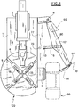
- FIG. 1 shows a tyre removal machine, indicated by 100, which comprises basically a frame or base 1 from which there upwardly extends a column 2, at the top end of which there is a longitudinally slidable horizontal bar 3.
- Said bar 3 supports a height-adjustable vertical rod 4 which is provided lowerly with a tool (not shown) for removing and mounting tyres from and onto their respective wheel rims.
- Said tool lies above a rotatable horizontal plate 5 which in the case under examination comprises four angularly equidistant heads 55 which slide radially for gripping the wheel rims.
- said heads 55 are of the double action type, ie they grip the rims both from the inside and from the outside.
- Said locator 8 acts as a support for the rim of a wheel 99 (upright) from which the bead is to be released, an arm 60 being hinged on said pin 6.
- a bead release tool 66 commonly known as a blade and provided with a projecting lever 44, is hinged on a horizontal transverse axis to the front end of the arm 60.
- the body of a single-acting cylinder-piston unit (not shown because it is of usual type) housed within the base is hinged to said box member 77 on a vertical axis 70.
- the rod 9 of said cylinder-piston unit extends towards the central region of the arm 60 where the means according to the invention are provided for the mutual coupling of said rod 9 and arm 60 during bead release.
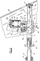
- said rod 9 terminates with a threaded portion 10 on which a coaxial prismatic bar 11 is screwed.
- the purpose of said cover 13 is to mask the aperture (not shown) provided in the box member 70 for passage of the rod 9, the purpose of said sleeve 14 being to prevent noisy contact between the cover 13 and said nut 12 and box member 77.
- the bar 11 is inserted, with an exact but freely slidable fit, into a conjugate prismatic seat 110 provided in a block 15.
- Said block 15 is housed within the arm 60, which is of channel cross-section with its mouth facing the base 1 (see Figure 3).
- the block 15 is hinged to the arm 60 on a vertical axis, which is indicated by 7 in all the accompanying figures and intersects the longitudinal axis of the bar 11. Specifically, said axis 7 is defined by two centrally holed coaxial discs 16 partly received in two conjugate recesses provided in the lower and upper faces of the block 15.
- Respective greater-diameter washers 161 rest against the outer ends of said discs 16, these latter and the washers 161 being torsionally fixed to the block 15 by at least two split pins 163 ( Figure 4).
- the bar 11 extends beyond the block 15, where it comprises a cap 17 the purpose of which is to prevent the block 15 withdrawing from the bar 11.
- Said cap 17 is provided with a damper ring 170, for example of rubber, the purpose of which is to prevent noisy contact between said block 15 and cap 17 when the arm 60 is rotated into its position of maximum opening.
- a damper ring 170 for example of rubber
- a rack portion 111 is provided on that side of the bar 11 facing the pin 6 on which the arm 60 is hinged.
- Said rack 11 is of the saw-tooth type, the teeth being inclined towards the base 1.
- a pawl 18 consisting of an elongate flat profiled body virtually parallel to the bar 11 ( Figure 3). Said pawl 18 is received, practically as an exact fit, in a seat 180 (see Figure 4) forming a lateral extension of the seat 110 within which the bar 11 slides.
- the pawl 18 is pivoted to the block 15 on a transverse axis 19 parallel to the axis 7, and lies between the bar 11 and an opposing profiled support 20 fixed to the block 15 by screws 21. On that side of the pawl 18 facing the bar 21 there are provided, at that end closer to the cap 17, three saw-teeth 112 having the same shape and dimensions as those of the toothing of the rack 111.
- pawl 18 and rack 111 are formed of very hard material by microfusion.
- the rack 111 is formed in one piece with the bar 11, however said rack 111 can be formed separately and then fixed to the bar 11 or rod 9.
- a compression spring 22 and a push rod 23 are provided on the opposite face of the pawl 18 on one and the other side of its pivot 19.
- Said pin 22 is partly received in a recess in said pawl 18, its outer end resting against the support 20.
- the purpose of the spring is to urge the pawl 18 into its release position.
- Said push rod 23 rests against a piston 24 which is slidingly received in a sealed manner within a hollow cylinder 25 which is fixed to the support 20.
- the purpose of the piston 24 is to urge the pawl 18 into its coupled position against the spring 22, there being provided between said piston 24 and cylinder 25 for this purpose a service chamber 26 into which a duct 260 opens.
- This latter is connected to a compressed air source via suitable valve means.
- the duct 260 is connected to the valve unit associated with that pedal of the tyre removal machine 100 which controls the elongation/ contraction of the cylinder-piston unit which operates the arm 60.
- the pawl 18 can be coupled and released by equivalent means. What is important is that this coupling and release are governed by the signals which control the contraction and elongation of said cylinder-piston unit.
- the invention operates as follows.
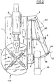
- the wheel 99 to undergo bead release which can be wide or narrow as shown in Figures 1 and 2 respectively, is rested against the locator 8 and the arm 60 is rotated towards this latter so that the tool is in contact with the bead of said wheel 99.
- said two planes define an acute angle with its opening facing the cap 17.
- the length of the rack 111 is such as to prevent excessive and inconvenient approach of the tool 66 to the locator 8 when the pawl 18 engages that end of the rack 111 close to the locator 8. Beyond said end the corresponding face of the bar 11 is perfectly smooth to enable the teeth 112 to slide along the bar when the wheel 22 undergoing bead release is fairly narrow.
Applications Claiming Priority (2)
| Application Number | Priority Date | Filing Date | Title |
|---|---|---|---|
| ITRE920008A IT1258032B (it) | 1992-02-28 | 1992-02-28 | Dispositivo stallonatore per macchine smontagomme |
| ITRE920008 | 1992-02-28 |
Publications (2)
| Publication Number | Publication Date |
|---|---|
| EP0557618A1 true EP0557618A1 (fr) | 1993-09-01 |
| EP0557618B1 EP0557618B1 (fr) | 1996-08-14 |
Family
ID=11398143
Family Applications (1)
| Application Number | Title | Priority Date | Filing Date |
|---|---|---|---|
| EP92201762A Expired - Lifetime EP0557618B1 (fr) | 1992-02-28 | 1992-06-16 | Appareil de briseur de talons d'une machine de démontage de pneumatiques |
Country Status (6)
| Country | Link |
|---|---|
| US (1) | US5381843A (fr) |
| EP (1) | EP0557618B1 (fr) |
| JP (1) | JP3188333B2 (fr) |
| DE (1) | DE69212797T2 (fr) |
| ES (1) | ES2091397T3 (fr) |
| IT (1) | IT1258032B (fr) |
Cited By (6)
| Publication number | Priority date | Publication date | Assignee | Title |
|---|---|---|---|---|
| EP1155880A2 (fr) * | 2000-05-18 | 2001-11-21 | Mondolfo Ferro - S.P.A. | Machine utilisée pour le montage et le démontage de roues de véhicules automobiles |
| EP1329342A1 (fr) * | 2002-01-17 | 2003-07-23 | SICAM S.r.l. | Machine améliorée à changer les pneumatiques |
| EP1880876A1 (fr) * | 2006-07-19 | 2008-01-23 | Giuliano S.P.A. | Unité de démonte-talons pour machines de changement de pneus |
| ITMO20110118A1 (it) * | 2011-05-20 | 2012-11-21 | Giuliano Group Spa | Gruppo stallonatore per macchine smontagomme |
| ITMO20110132A1 (it) * | 2011-05-24 | 2012-11-25 | Giuliano Group Spa | Gruppo stallonatore perfezionato per macchine smontagomme o simili |
| WO2017081554A1 (fr) * | 2015-11-10 | 2017-05-18 | Snap-On Equipment S.R.L. | Machine de changement de pneu |
Families Citing this family (13)
| Publication number | Priority date | Publication date | Assignee | Title |
|---|---|---|---|---|
| US6056034A (en) * | 1998-05-20 | 2000-05-02 | Matnick; Michael | Difficult to mount tire changer and method for handling thereof |
| US6182736B1 (en) | 1998-06-15 | 2001-02-06 | Hennessy Industries, Inc. | Helper arm for a rim holding tire changer |
| IT1304922B1 (it) * | 1998-11-06 | 2001-04-05 | G S Srl | Macchina per smontare e montare pneumatici. |
| IT1310590B1 (it) * | 1999-05-14 | 2002-02-19 | Giuliano Srl | Stazione multifunzionale per il montaggio e lo smontaggio dipneumatici sia di tipo convenzionale sia speciale. |
| CA2354745A1 (fr) * | 2001-08-06 | 2003-02-06 | Ernie J. Shwaykowski | Dispositif de levage de roue |
| ITRE20030095A1 (it) * | 2003-10-14 | 2005-04-15 | Corghi Spa | Dispositivo stallonatore per macchine smontagomme. |
| IT1396966B1 (it) * | 2009-12-16 | 2012-12-20 | Giuliano S P A Ora Giuliano Group S P A | Gruppo stallonatore per macchine smontagomme |
| US9193227B1 (en) * | 2011-09-23 | 2015-11-24 | Hennessy Industries, Inc. | Releasable swing arm clamp for a wheel servicing machine |
| US9624968B1 (en) | 2012-10-31 | 2017-04-18 | Hennessy Industries, Inc. | Swing arm latch for a wheel servicing machine |
| ITMO20130110A1 (it) * | 2013-04-23 | 2014-10-24 | Giuliano Group Spa | Gruppo stallonatore per macchine smontagomme o simili |
| WO2015013463A1 (fr) | 2013-07-23 | 2015-01-29 | Hennessy Industries, Inc. | Machine à changer les pneus comportant un bras de décollage des bourrelets |
| RU2670593C2 (ru) * | 2014-03-14 | 2018-10-23 | СИКАМ С.р.л. | Узел для разбортовки |
| CN110774839B (zh) * | 2019-11-26 | 2020-09-29 | 捷德凯托普(江苏)机械有限公司 | 一种扩胎与夹胎两用工具 |
Citations (6)
| Publication number | Priority date | Publication date | Assignee | Title |
|---|---|---|---|---|
| US1646511A (en) * | 1925-03-23 | 1927-10-25 | Weaver Mfg Co | Tire changer |
| US2523448A (en) * | 1948-01-02 | 1950-09-26 | John H Reitz | Jack type tire bead and rim separating device |
| US4884611A (en) * | 1988-10-24 | 1989-12-05 | Schmidt Raymond H | Tire changing machine |
| DE9101930U1 (fr) * | 1991-02-19 | 1991-06-06 | Stahlgruber Otto Gruber Gmbh & Co, 8000 Muenchen, De | |
| US5050659A (en) * | 1990-04-27 | 1991-09-24 | G. S. S.R.L. | Machine for the removal and replacement of tires for the wheels of automobiles |
| EP0448042A2 (fr) * | 1990-03-23 | 1991-09-25 | BUTLER ENGINEERING & MARKETING S.r.l. | Machine à démonter les pneumatiques |
Family Cites Families (4)
| Publication number | Priority date | Publication date | Assignee | Title |
|---|---|---|---|---|
| JPS57178907A (en) * | 1981-04-30 | 1982-11-04 | Kenichi Takahata | Tire disassembling device |
| US5088539A (en) * | 1990-09-11 | 1992-02-18 | Fmc Corporation | Tire changing apparatus |
| US5226465A (en) * | 1991-02-19 | 1993-07-13 | Stahlgruber Otto Gruber Gmbh & Co. | Mounting device for motor vehicle tires |
| IT1249760B (it) * | 1991-05-03 | 1995-03-17 | Sicesp Elettromeccaniche | Gruppo stallonatore ad elevata flessibilita' di impiego. |
-
1992
- 1992-02-28 IT ITRE920008A patent/IT1258032B/it active IP Right Grant
- 1992-06-16 EP EP92201762A patent/EP0557618B1/fr not_active Expired - Lifetime
- 1992-06-16 ES ES92201762T patent/ES2091397T3/es not_active Expired - Lifetime
- 1992-06-16 DE DE69212797T patent/DE69212797T2/de not_active Expired - Fee Related
-
1993
- 1993-02-02 JP JP01524993A patent/JP3188333B2/ja not_active Expired - Fee Related
- 1993-02-24 US US08/021,870 patent/US5381843A/en not_active Expired - Lifetime
Patent Citations (6)
| Publication number | Priority date | Publication date | Assignee | Title |
|---|---|---|---|---|
| US1646511A (en) * | 1925-03-23 | 1927-10-25 | Weaver Mfg Co | Tire changer |
| US2523448A (en) * | 1948-01-02 | 1950-09-26 | John H Reitz | Jack type tire bead and rim separating device |
| US4884611A (en) * | 1988-10-24 | 1989-12-05 | Schmidt Raymond H | Tire changing machine |
| EP0448042A2 (fr) * | 1990-03-23 | 1991-09-25 | BUTLER ENGINEERING & MARKETING S.r.l. | Machine à démonter les pneumatiques |
| US5050659A (en) * | 1990-04-27 | 1991-09-24 | G. S. S.R.L. | Machine for the removal and replacement of tires for the wheels of automobiles |
| DE9101930U1 (fr) * | 1991-02-19 | 1991-06-06 | Stahlgruber Otto Gruber Gmbh & Co, 8000 Muenchen, De |
Non-Patent Citations (1)
| Title |
|---|
| PATENT ABSTRACTS OF JAPAN vol. 7, no. 24 (M-189)(1169) 29 January 1983 & JP-A-57 178 907 ( KENICHI TAKAHATA ) 4 November 1982 * |
Cited By (18)
| Publication number | Priority date | Publication date | Assignee | Title |
|---|---|---|---|---|
| EP1155880A2 (fr) * | 2000-05-18 | 2001-11-21 | Mondolfo Ferro - S.P.A. | Machine utilisée pour le montage et le démontage de roues de véhicules automobiles |
| EP1155880A3 (fr) * | 2000-05-18 | 2003-01-29 | Mondolfo Ferro - S.P.A. | Machine utilisée pour le montage et le démontage de roues de véhicules automobiles |
| EP1329342A1 (fr) * | 2002-01-17 | 2003-07-23 | SICAM S.r.l. | Machine améliorée à changer les pneumatiques |
| EP1880876A1 (fr) * | 2006-07-19 | 2008-01-23 | Giuliano S.P.A. | Unité de démonte-talons pour machines de changement de pneus |
| US7591295B2 (en) | 2006-07-19 | 2009-09-22 | Giuliano S.P.A. | Bead breaking unit for tire changing machines |
| CN102795063A (zh) * | 2011-05-20 | 2012-11-28 | 古丽亚诺集团股份公司 | 用于轮胎更换机的胎圈分离单元 |
| EP2524819A1 (fr) * | 2011-05-20 | 2012-11-21 | Giuliano Group S.p.A. | Unité de démonte-talons pour machines de changement de pneus |
| ITMO20110118A1 (it) * | 2011-05-20 | 2012-11-21 | Giuliano Group Spa | Gruppo stallonatore per macchine smontagomme |
| US9114675B2 (en) | 2011-05-20 | 2015-08-25 | Giuliano Group S.P.A. | Bead breaking unit for tyre changing machines |
| CN102795063B (zh) * | 2011-05-20 | 2015-11-25 | 古丽亚诺集团股份公司 | 用于轮胎更换机的胎圈分离单元 |
| ITMO20110132A1 (it) * | 2011-05-24 | 2012-11-25 | Giuliano Group Spa | Gruppo stallonatore perfezionato per macchine smontagomme o simili |
| EP2527166A1 (fr) * | 2011-05-24 | 2012-11-28 | Giuliano Group S.p.A. | Unité de démonte-talons pour machines de changement de pneus |
| US8826962B2 (en) | 2011-05-24 | 2014-09-09 | Giuliano Group S.P.A. | Upgraded bead breaking unit for tyre changing machines or the like |
| WO2017081554A1 (fr) * | 2015-11-10 | 2017-05-18 | Snap-On Equipment S.R.L. | Machine de changement de pneu |
| CN108430808A (zh) * | 2015-11-10 | 2018-08-21 | 斯耐普昂仪器有限公司 | 轮胎拆装机 |
| CN108430808B (zh) * | 2015-11-10 | 2020-10-16 | 斯耐普昂仪器有限公司 | 轮胎拆装机 |
| US10828949B2 (en) | 2015-11-10 | 2020-11-10 | Snap-On Equipment S.R.L. | Tyre changing machine |
| US11148482B2 (en) | 2015-11-10 | 2021-10-19 | Snap-On Equipment S.R.L. | Tyre changing machine |
Also Published As
| Publication number | Publication date |
|---|---|
| DE69212797T2 (de) | 1996-12-19 |
| EP0557618B1 (fr) | 1996-08-14 |
| DE69212797D1 (de) | 1996-09-19 |
| ITRE920008A0 (it) | 1992-02-28 |
| ES2091397T3 (es) | 1996-11-01 |
| JP3188333B2 (ja) | 2001-07-16 |
| IT1258032B (it) | 1996-02-20 |
| US5381843A (en) | 1995-01-17 |
| JPH05278417A (ja) | 1993-10-26 |
| ITRE920008A1 (it) | 1993-08-28 |
Similar Documents
| Publication | Publication Date | Title |
|---|---|---|
| EP0557618B1 (fr) | Appareil de briseur de talons d'une machine de démontage de pneumatiques | |
| US5472034A (en) | Bead guide implement for facilitating the mounting of tires onto respective wheel rims | |
| US4222426A (en) | Bead breaker mechanism for a tire changer machine | |
| US2413010A (en) | Tire handling stand | |
| US3972363A (en) | Machine for changing giant tires | |
| US2986204A (en) | Lever operated tire slitting tool with blade holder having blade adjustment means | |
| EP1026017A2 (fr) | Machine pour le montage et le démontage de pneus spéciaux | |
| EP0659597B1 (fr) | Dispositif pour faciliter le démontage et le montage de pneu d'une jante de roue, pour machines à démonter les pneux en général | |
| US6202510B1 (en) | Tire plug insertion tool | |
| US2900017A (en) | Circumferentially traveling shoe type portable tire mounting device | |
| US3865172A (en) | Tire bead breaking apparatus | |
| US3493030A (en) | Tire changing stand with rotatable rim gripping table | |
| US3032094A (en) | Tire changer machine improvements | |
| US6622636B2 (en) | Device for automatically moving vehicles along guide ways of lifts | |
| US4969499A (en) | Tire mounting apparatus | |
| US6609293B2 (en) | Device for operating on tires of “SYSTEM PAX” type | |
| US2812805A (en) | Automatically adjustable bead breaker | |
| US3164197A (en) | Tire tool | |
| US3782442A (en) | Adjustable thrust mechanism for separating the bonds between annular components of pneumatic tire-wheel assemblies | |
| US3858637A (en) | Device for fitting and removing a tire of vehicle wheels | |
| US3056449A (en) | Tire demounting tool | |
| US2619158A (en) | Lever actuated tire bead forcing tool | |
| US4355675A (en) | Device for removing a tire from its rim | |
| US2844194A (en) | Portable power-operated tire removing tool | |
| US2653653A (en) | Circumferentially adjustable tire removing device |
Legal Events
| Date | Code | Title | Description |
|---|---|---|---|
| PUAI | Public reference made under article 153(3) epc to a published international application that has entered the european phase |
Free format text: ORIGINAL CODE: 0009012 |
|
| AK | Designated contracting states |
Kind code of ref document: A1 Designated state(s): DE ES FR IT |
|
| 17P | Request for examination filed |
Effective date: 19940127 |
|
| 17Q | First examination report despatched |
Effective date: 19950516 |
|
| GRAH | Despatch of communication of intention to grant a patent |
Free format text: ORIGINAL CODE: EPIDOS IGRA |
|
| GRAH | Despatch of communication of intention to grant a patent |
Free format text: ORIGINAL CODE: EPIDOS IGRA |
|
| GRAA | (expected) grant |
Free format text: ORIGINAL CODE: 0009210 |
|
| AK | Designated contracting states |
Kind code of ref document: B1 Designated state(s): DE ES FR IT |
|
| REF | Corresponds to: |
Ref document number: 69212797 Country of ref document: DE Date of ref document: 19960919 |
|
| ET | Fr: translation filed | ||
| REG | Reference to a national code |
Ref country code: ES Ref legal event code: FG2A Ref document number: 2091397 Country of ref document: ES Kind code of ref document: T3 |
|
| ITF | It: translation for a ep patent filed |
Owner name: ING. C. CORRADINI & C. S.R.L. |
|
| PLBE | No opposition filed within time limit |
Free format text: ORIGINAL CODE: 0009261 |
|
| STAA | Information on the status of an ep patent application or granted ep patent |
Free format text: STATUS: NO OPPOSITION FILED WITHIN TIME LIMIT |
|
| 26N | No opposition filed | ||
| PGFP | Annual fee paid to national office [announced via postgrant information from national office to epo] |
Ref country code: ES Payment date: 20050504 Year of fee payment: 14 |
|
| PGFP | Annual fee paid to national office [announced via postgrant information from national office to epo] |
Ref country code: FR Payment date: 20050608 Year of fee payment: 14 |
|
| PGFP | Annual fee paid to national office [announced via postgrant information from national office to epo] |
Ref country code: DE Payment date: 20050624 Year of fee payment: 14 |
|
| PG25 | Lapsed in a contracting state [announced via postgrant information from national office to epo] |
Ref country code: ES Free format text: LAPSE BECAUSE OF NON-PAYMENT OF DUE FEES Effective date: 20060617 |
|
| PG25 | Lapsed in a contracting state [announced via postgrant information from national office to epo] |
Ref country code: DE Free format text: LAPSE BECAUSE OF NON-PAYMENT OF DUE FEES Effective date: 20070103 |
|
| REG | Reference to a national code |
Ref country code: FR Ref legal event code: ST Effective date: 20070228 |
|
| REG | Reference to a national code |
Ref country code: ES Ref legal event code: FD2A Effective date: 20060617 |
|
| PG25 | Lapsed in a contracting state [announced via postgrant information from national office to epo] |
Ref country code: FR Free format text: LAPSE BECAUSE OF NON-PAYMENT OF DUE FEES Effective date: 20060630 |
|
| PGFP | Annual fee paid to national office [announced via postgrant information from national office to epo] |
Ref country code: IT Payment date: 20080529 Year of fee payment: 17 |
|
| PG25 | Lapsed in a contracting state [announced via postgrant information from national office to epo] |
Ref country code: IT Free format text: LAPSE BECAUSE OF NON-PAYMENT OF DUE FEES Effective date: 20090616 |