EP0557367B1 - Exhaust pressure modulation valve - Google Patents
Exhaust pressure modulation valve Download PDFInfo
- Publication number
- EP0557367B1 EP0557367B1 EP91920141A EP91920141A EP0557367B1 EP 0557367 B1 EP0557367 B1 EP 0557367B1 EP 91920141 A EP91920141 A EP 91920141A EP 91920141 A EP91920141 A EP 91920141A EP 0557367 B1 EP0557367 B1 EP 0557367B1
- Authority
- EP
- European Patent Office
- Prior art keywords
- butterfly
- valve
- pressure
- spindle
- inlet
- Prior art date
- Legal status (The legal status is an assumption and is not a legal conclusion. Google has not performed a legal analysis and makes no representation as to the accuracy of the status listed.)
- Expired - Lifetime
Links
- 239000012530 fluid Substances 0.000 claims description 5
- 230000004044 response Effects 0.000 claims description 4
- 230000000694 effects Effects 0.000 description 3
- 229930195733 hydrocarbon Natural products 0.000 description 3
- 150000002430 hydrocarbons Chemical class 0.000 description 3
- 230000009471 action Effects 0.000 description 2
- 239000000446 fuel Substances 0.000 description 1
- 238000010438 heat treatment Methods 0.000 description 1
- 230000006872 improvement Effects 0.000 description 1
- 238000000034 method Methods 0.000 description 1
- 230000009467 reduction Effects 0.000 description 1
- 238000010792 warming Methods 0.000 description 1
Images



Classifications
-
- F—MECHANICAL ENGINEERING; LIGHTING; HEATING; WEAPONS; BLASTING
- F02—COMBUSTION ENGINES; HOT-GAS OR COMBUSTION-PRODUCT ENGINE PLANTS
- F02D—CONTROLLING COMBUSTION ENGINES
- F02D9/00—Controlling engines by throttling air or fuel-and-air induction conduits or exhaust conduits
- F02D9/04—Controlling engines by throttling air or fuel-and-air induction conduits or exhaust conduits concerning exhaust conduits
- F02D9/06—Exhaust brakes
-
- F—MECHANICAL ENGINEERING; LIGHTING; HEATING; WEAPONS; BLASTING
- F16—ENGINEERING ELEMENTS AND UNITS; GENERAL MEASURES FOR PRODUCING AND MAINTAINING EFFECTIVE FUNCTIONING OF MACHINES OR INSTALLATIONS; THERMAL INSULATION IN GENERAL
- F16K—VALVES; TAPS; COCKS; ACTUATING-FLOATS; DEVICES FOR VENTING OR AERATING
- F16K15/00—Check valves
- F16K15/02—Check valves with guided rigid valve members
- F16K15/03—Check valves with guided rigid valve members with a hinged closure member or with a pivoted closure member
- F16K15/033—Check valves with guided rigid valve members with a hinged closure member or with a pivoted closure member spring-loaded
-
- F—MECHANICAL ENGINEERING; LIGHTING; HEATING; WEAPONS; BLASTING
- F16—ENGINEERING ELEMENTS AND UNITS; GENERAL MEASURES FOR PRODUCING AND MAINTAINING EFFECTIVE FUNCTIONING OF MACHINES OR INSTALLATIONS; THERMAL INSULATION IN GENERAL
- F16K—VALVES; TAPS; COCKS; ACTUATING-FLOATS; DEVICES FOR VENTING OR AERATING
- F16K15/00—Check valves
- F16K15/02—Check valves with guided rigid valve members
- F16K15/03—Check valves with guided rigid valve members with a hinged closure member or with a pivoted closure member
- F16K15/035—Check valves with guided rigid valve members with a hinged closure member or with a pivoted closure member with a plurality of valve members
- F16K15/036—Dual valve members with hinges crossing the flow line substantially diametrical
-
- F—MECHANICAL ENGINEERING; LIGHTING; HEATING; WEAPONS; BLASTING
- F16—ENGINEERING ELEMENTS AND UNITS; GENERAL MEASURES FOR PRODUCING AND MAINTAINING EFFECTIVE FUNCTIONING OF MACHINES OR INSTALLATIONS; THERMAL INSULATION IN GENERAL
- F16K—VALVES; TAPS; COCKS; ACTUATING-FLOATS; DEVICES FOR VENTING OR AERATING
- F16K15/00—Check valves
- F16K15/18—Check valves with actuating mechanism; Combined check valves and actuated valves
- F16K15/182—Check valves with actuating mechanism; Combined check valves and actuated valves with actuating mechanism
- F16K15/1821—Check valves with actuating mechanism; Combined check valves and actuated valves with actuating mechanism for check valves with a hinged or pivoted closure member
-
- F—MECHANICAL ENGINEERING; LIGHTING; HEATING; WEAPONS; BLASTING
- F02—COMBUSTION ENGINES; HOT-GAS OR COMBUSTION-PRODUCT ENGINE PLANTS
- F02B—INTERNAL-COMBUSTION PISTON ENGINES; COMBUSTION ENGINES IN GENERAL
- F02B3/00—Engines characterised by air compression and subsequent fuel addition
- F02B3/06—Engines characterised by air compression and subsequent fuel addition with compression ignition
-
- F—MECHANICAL ENGINEERING; LIGHTING; HEATING; WEAPONS; BLASTING
- F16—ENGINEERING ELEMENTS AND UNITS; GENERAL MEASURES FOR PRODUCING AND MAINTAINING EFFECTIVE FUNCTIONING OF MACHINES OR INSTALLATIONS; THERMAL INSULATION IN GENERAL
- F16K—VALVES; TAPS; COCKS; ACTUATING-FLOATS; DEVICES FOR VENTING OR AERATING
- F16K2200/00—Details of valves
- F16K2200/40—Bleeding means in closed position of the valve, e.g. bleeding passages
-
- Y—GENERAL TAGGING OF NEW TECHNOLOGICAL DEVELOPMENTS; GENERAL TAGGING OF CROSS-SECTIONAL TECHNOLOGIES SPANNING OVER SEVERAL SECTIONS OF THE IPC; TECHNICAL SUBJECTS COVERED BY FORMER USPC CROSS-REFERENCE ART COLLECTIONS [XRACs] AND DIGESTS
- Y10—TECHNICAL SUBJECTS COVERED BY FORMER USPC
- Y10T—TECHNICAL SUBJECTS COVERED BY FORMER US CLASSIFICATION
- Y10T137/00—Fluid handling
- Y10T137/7722—Line condition change responsive valves
- Y10T137/7837—Direct response valves [i.e., check valve type]
- Y10T137/7847—With leak passage
-
- Y—GENERAL TAGGING OF NEW TECHNOLOGICAL DEVELOPMENTS; GENERAL TAGGING OF CROSS-SECTIONAL TECHNOLOGIES SPANNING OVER SEVERAL SECTIONS OF THE IPC; TECHNICAL SUBJECTS COVERED BY FORMER USPC CROSS-REFERENCE ART COLLECTIONS [XRACs] AND DIGESTS
- Y10—TECHNICAL SUBJECTS COVERED BY FORMER USPC
- Y10T—TECHNICAL SUBJECTS COVERED BY FORMER US CLASSIFICATION
- Y10T137/00—Fluid handling
- Y10T137/7722—Line condition change responsive valves
- Y10T137/7837—Direct response valves [i.e., check valve type]
- Y10T137/7876—With external means for opposing bias
-
- Y—GENERAL TAGGING OF NEW TECHNOLOGICAL DEVELOPMENTS; GENERAL TAGGING OF CROSS-SECTIONAL TECHNOLOGIES SPANNING OVER SEVERAL SECTIONS OF THE IPC; TECHNICAL SUBJECTS COVERED BY FORMER USPC CROSS-REFERENCE ART COLLECTIONS [XRACs] AND DIGESTS
- Y10—TECHNICAL SUBJECTS COVERED BY FORMER USPC
- Y10T—TECHNICAL SUBJECTS COVERED BY FORMER US CLASSIFICATION
- Y10T137/00—Fluid handling
- Y10T137/7722—Line condition change responsive valves
- Y10T137/7837—Direct response valves [i.e., check valve type]
- Y10T137/7898—Pivoted valves
Definitions
- This invention relates to an exhaust pressure modulation valve, and in particular to a valve for the exhaust system of a diesel engined vehicle.
- 'exhaust brakes' can be fitted into the vehicle exhaust system and which, by generating a back pressure, can assist the vehicle in braking. Similar devices, termed 'warm-up' valves, can also assist in cab heating and in reducing the emission of unburnt hydrocarbons by reducing the time for the engine to reach normal operating temperature.
- DE-A-3211920 discloses an exhaust pressure modulation valve comprising a butterfly valve with an offset butterfly spindle.
- the butterfly valve is actuated by an hydraulic or pneumatic piston arrangement.
- DE-A-3835545 shows a butterfly valve symmetrically pivotally mounted with a duct, having two apertures symmetrically situated in the butterfly about the pivot axis.
- FR-A-1198272 shows an exhaust pressure modulation valve according to the preamble of claim 1.
- the level of back pressure generated (typically 2-8 bar) must not exceed the maximum design back pressure of the engine, which is limited, for example, by the load of the engine exhaust valve springs.
- the exhaust brake normally a butterfly valve or a sliding gate, must either be locked into a position which is almost but not quite closed, allowing some exhaust gas to escape around the edge, or have one or more bleed passages formed in or around the butterfly or sliding gate. It is usual in practice to drill a hole or holes, and allow the butterfly or gate to sit in a fully closed position.
- the leakage rate is determined by the size and number of bleed passages and is dictated by the maximum allowable back pressure when the engine is running at the highest speed, and the flow of exhaust gas through the exhaust brake is thus at its maximum.
- the bleed passages may total 200mm 2 for a butterfly diameter of 100 mm, about 2.5% of total butterfly area.
- Warm-up valves are desirable because the time for the engine to reach operating temperature is substantially reduced, typically from 80 to 40 minutes - this leads to a substantial reduction in the emission of unburnt hydrocarbons and a considerable improvement in fuel economy.
- a warm-up valve when used to reduce the time for the engine to reach normal temperature, are not however the same as those applicable to exhaust brakes.
- a very small bleed passage is required, typically not more than 5 mm in diameter for a butterfly diameter of 100 mm, because the engine is running at tickover speed, and the vehicle is stationary; back pressure generated is about in the range 0.5-2.0 bar, depending on the engine application.
- the back pressure generated by a warm-up valve will be only about 254 of the maximum back pressure generated during operation of an exhaust brake.
- a conventional exhaust brake would thus be useless as an aid to reducing engine warm-up time because the bleed apertures are too large to generate significant back pressure at these low engine speeds and gas flow rates.
- Warm-up valves may be driver operated, to minimise the time for the cab heater to begin to work, or may be operated automatically in response to emission control apparatus, to reduce the quantity of unburnt hydrocarbons exhausted whilst the engine is warming up.
- a particular danger with warm-up valves is that the driver may drive off with the warm-up valve closed; because the bleed passage is very small, the back pressure generated may quickly exceed the design limit of the engine, and engine damage may follow.
- the present invention seeks to provide an exhaust pressure modulation valve, which combines the functions of an exhaust brake and warm-up valve and has a single butterfly to close the exhaust tract.
- an exhaust pressure modulation valve comprising a body having an inlet, an outlet, and a passageway between said inlet and outlet, a butterfly pivotable in the body to close communication between said inlet and outlet, said butterfly having a spindle pivot axis and said spindle pivot axis being offset from an axis of symmetry of said passageway such that a resultant torque generated in response to increasing pressure at said inlet tends to open the butterfly, said valve further comprising operating means for closing said butterfly and adapted to apply to said spindle pivot axis a closing torque of the same magnitude as said resultant torque generated at a pre-determined pressure at said inlet, and a bleed means from one side of said butterfly to the other comprising an aperture in the butterfly, said bleed means being sized to ensure a significant back pressure when said butterfly is in use closed and the flow of gas through said valve is significantly less than the maximum flow of gas through said valve, characterised in that said bleed means have a cross-sectional area not greater than 0.25%
- Such a valve has a butterfly which reacts to inlet pressure so that the butterfly opens when the predetermined inlet pressure is exceeded.
- the predetermined inlet pressure is set at or just less than the safe maximum design back pressure of the engine thus ensuring that the butterfly will open if excessive back pressures are generated.
- pre-determined pressure would be in the range 2-8 bar, depending on the application, and the bleed means would be sized to impose a back pressure of about 25% of maximum or about 0.5-2.0 bar at flow rates commensurate with an engine running at tickover speed.
- said bleed means has a total area of less than 0.25% of the area of said butterfly.
- the bleed means is in size an order of magnitude less than the bypass aperture in a conventional exhaust brake.
- a single bleed aperture having an area of 12.5 mm 2 was found adequate to impose a back pressure of approximately 0.5 bar at engine tickover; the maximum permissible back pressure at maximum engine speed being about 4 bar.
- the valve is safe when used in 'warm-up' mode because the butterfly will react to excessive back pressures.
- the area of said bleed means is too small to significantly affect reactive operation of the butterfly and in any event the pre-determined inlet pressure can be set at a level which compensates for the effect of a small throughput of exhaust gas.
- Such an exhaust pressure modulation valve provides three functions with a single butterfly and additionally significantly improves the effectiveness of the exhaust brake at moderate engine speeds.
- said bleed means comprises a single bleed aperture; in a preferred embodiment, a hole in the butterfly is provided. In a preferred embodiment the hole is on the opposite side of said offset axis to said axis of symmetry. In this arrangement, the bleed aperture is on the side of the butterfly with smallest area exposed to inlet pressure; accordingly the turning movement tending to open the butterfly is not reduced.
- the offset of the butterfly pivot axis is typically in the range 2 to 4 mm, for a valve having a circular exhaust tract and a diameter of 100-150 mm.
- the butterfly spindle is loaded by a return spring and operably connected to actuator means via a control spring whereby the resultant torque tending to close the butterfly can be set by for example, appropriate selection of one or both of the springs so as to balance the opening torque generated at a predetermined level of back pressure.
- valve closing torque be adjustable.
- adjustment of the applied torque can be achieved by varying the length of the torque arm. This arrangement is suitable whether the actuator is mechanically electrically, pneumatically or hydraulically operated.
- Pneumatic actuators are usually connected to a compressed air supply line providing line pressure to act against an internal return spring.
- a pneumatic or indeed a hydraulic actuator is connected to the fluid supply via a pressure control valve which is preferably adjustable to control the pressure of fluid admitted to the cylinder of the actuator, whereby the resultant force (tending to close the valve) can be varied as appropriate to balance the maximum permitted back pressure.
- Actuation of the butterfly may be in response to driver action, for example in exhaust brake or cab heat mode, or may be under automatic control, for example to control exhaust emissions.
- the predetermined pressure at which the butterfly opens reactively may be varied by control means in accordance with engine management or other systems to suit particular operating requirements.
- Fig. 1 illustrates the difference between a conventional exhaust brake and a reactive exhaust brake.
- the dotted line illustrates the effect of conventional exhaust brake on back pressure (P) with increasing engine gas flow (F); gas flow of course increases with increasing engine speed.
- a conventional exhaust brake includes one or more relatively large holes in the butterfly so that at maximum gas flow (maximum engine speed) the back pressure developed by the exhaust brake does not exceed the maximum design back pressure of the engine - this is illustrated by point c1.
- the butterfly holes are too large to generate an effective back pressure, and in the normal operating range of the engine, the back pressure generated may be only 20-50% of the maximum permissible - illustrated by points C2 and C3.
- the solid line of Fig. illustrates the operating curve of a reactive exhaust brake according to the invention.
- the butterfly contains only a relatively small aperture (typically less than one-tenth of the total area of the holes in a conventional exhaust brake butterfly) and thus on application the exhaust brake generates almost maximum back pressure throughout the normal operating range of the engine.
- the exhaust brake of Figs. 2-4 includes a cylindrical valve body 10 for connection by end flanges 11 to an exhaust tract and within which is a butterfly-type valve 12 mounted upon a spindle 14 to pivot about an axis displaced by a predetermined distance d (typically 3 mm for a valve of up to 5" diameter) from a diameter of the valve body 10.
- the direction of gas flow is indicated by arrow D.
- Rigidly mounted on the butterfly valve spindle 14 externally of the valve body 10 is a double ended lever 16, one end 18 of which is connected to a return spring 20 anchored at a fixed abutment 21 of a mounting plate 19.
- the other end 22 of lever 16 is connected via an override spring 24 to a control cable 26 leading to the vehicle cab (not shown) for operation by the driver.
- the mounting plate includes an abutment 27 for the cable sheath 28a.
- valve 12 In operation the valve 12 is closed by pulling the cable 26 in the direction of abutment 27, the cable spring 24 extends, generating a torque which opposes the torque of the return spring 20 and the torque generated on the spindle 14 by exhaust gas back pressure. This latter torque is a result of the spindle axis being offset from the centreline of the valve body 10.
- the valve 12 is thus reactive and opens at a pre-set back pressure to prevent engine damage while ensuring that the valve is fully effective as an exhaust brake throughout the normal operating range of the engine.
- the return spring 20 is capable of re-opening the valve 12 when the closing force is removed, in this case when the cable 26 is relaxed.
- the offset of the valve spindle 14 allows the gas pressure to generate an opening torque proportional to the back pressure.
- the valve 12 also includes a hole 29, as illustrated in Fig. 4, or a bypass through the wall of the body 10, which allows the valve to be used as a warm-up valve to bring the engine up to working temperature.
- the valve 12 is closed when the engine has just been started from cold.
- the valve imposes a relatively low back pressure on the engine (typically 1 bar) because the engine is running at slow speed (around 800 rpm) and the bleed hole 29 permits a small throughput of exhaust gas.
- This small back pressure dramatically reduces the time for the engine to reach normal operating temperature, typically from around 80 to 40 minutes.
- the valve will operate as a reactive exhaust brake as described above. Engine damage when used as a warm-up valve is thus prevented.
- the valve is designed to prevent back pressure being generated above prescribed levels if the butterfly is closed when the engine RPM, and thus the gas flow, is large enough to generate excessive back pressure, or if the valve is held closed while engine RPM increases above that which would generate an excessive back pressure.
- valve is closed by pneumatic, electric vacuum, hydraulic or any other means.
- a pneumatically operated butterfly valve it is possible to make use of the return spring within the pneumatic actuator itself.
- One such embodiment is shown in Figs. 5 to 7.
- the butterfly valve 32 and cylindrical valve body 30 with flanges 31, are arranged in substantially the same manner as shown in Figs. 2 to 4.
- one end flange 31a is adapted for mounting directly to a turbocharger outlet.
- One end 34 of the lever 36 is connected to an adjustable piston rod 38 of a pneumatic actuator 40 held by the actuator return spring against the stop 42 with the butterfly 32 in the fully open position.
- Spindle offset is indicated by 'd', and gas flow by arrow D.
- the butterfly 32 is closed by compressed air supplied to the actuator 40 by a pressure control valve 44 connected to a source S of compressed air, the air supplied acting against the actuator return spring to generate a closing torque on the butterfly valve 32 and urge the valve closed.
- the pressure of air supplied to the actuator is controlled by the valve 44 which is set to hold the valve closed against the actuator return spring and the torque generated by the exhaust gas at the prescribed maximum back pressure level.
- the level of back pressure required can be achieved by a combination of butterfly offset, lever length, actuator return spring and the pressure of air supplied to the actuator.
- Another method of giving a suitable actuator load is to dispense with the pressure control valve and vary the actuator return spring or springs.
- the spring or springs may be adjustable at the actuator or selected to apply a predetermined load to suit a particular application.
Landscapes
- Engineering & Computer Science (AREA)
- General Engineering & Computer Science (AREA)
- Mechanical Engineering (AREA)
- Chemical & Material Sciences (AREA)
- Combustion & Propulsion (AREA)
- Control Of Throttle Valves Provided In The Intake System Or In The Exhaust System (AREA)
Abstract
Description
- This invention relates to an exhaust pressure modulation valve, and in particular to a valve for the exhaust system of a diesel engined vehicle.
- Devices known as 'exhaust brakes' can be fitted into the vehicle exhaust system and which, by generating a back pressure, can assist the vehicle in braking. Similar devices, termed 'warm-up' valves, can also assist in cab heating and in reducing the emission of unburnt hydrocarbons by reducing the time for the engine to reach normal operating temperature.
- DE-A-3211920 discloses an exhaust pressure modulation valve comprising a butterfly valve with an offset butterfly spindle. The butterfly valve is actuated by an hydraulic or pneumatic piston arrangement.
- DE-A-3835545 shows a butterfly valve symmetrically pivotally mounted with a duct, having two apertures symmetrically situated in the butterfly about the pivot axis.
- FR-A-1198272 shows an exhaust pressure modulation valve according to the preamble of claim 1.
- In general the greater the back pressure generated by an exhaust brake, the more effective the braking effect becomes. But the level of back pressure generated (typically 2-8 bar) must not exceed the maximum design back pressure of the engine, which is limited, for example, by the load of the engine exhaust valve springs.
- To limit the back pressure, the exhaust brake, normally a butterfly valve or a sliding gate, must either be locked into a position which is almost but not quite closed, allowing some exhaust gas to escape around the edge, or have one or more bleed passages formed in or around the butterfly or sliding gate. It is usual in practice to drill a hole or holes, and allow the butterfly or gate to sit in a fully closed position. The leakage rate is determined by the size and number of bleed passages and is dictated by the maximum allowable back pressure when the engine is running at the highest speed, and the flow of exhaust gas through the exhaust brake is thus at its maximum. Typically the bleed passages may total 200mm2 for a butterfly diameter of 100 mm, about 2.5% of total butterfly area.
- It follows that at lower engine speeds, especially in the normal driving range, the bleed holes apertures are larger than is necessary to reach the maximum back pressure at these lower speeds. Accordingly such exhaust brakes are rather ineffective at moderate gas flow rates because the back pressure generated is much less than the maximum permissible.
- Warm-up valves are desirable because the time for the engine to reach operating temperature is substantially reduced, typically from 80 to 40 minutes - this leads to a substantial reduction in the emission of unburnt hydrocarbons and a considerable improvement in fuel economy.
- The design requirements of a warm-up valve, when used to reduce the time for the engine to reach normal temperature, are not however the same as those applicable to exhaust brakes. In general only a very small bleed passage is required, typically not more than 5 mm in diameter for a butterfly diameter of 100 mm, because the engine is running at tickover speed, and the vehicle is stationary; back pressure generated is about in the range 0.5-2.0 bar, depending on the engine application. In a typical application, the back pressure generated by a warm-up valve will be only about 254 of the maximum back pressure generated during operation of an exhaust brake. A conventional exhaust brake would thus be useless as an aid to reducing engine warm-up time because the bleed apertures are too large to generate significant back pressure at these low engine speeds and gas flow rates.
- Warm-up valves may be driver operated, to minimise the time for the cab heater to begin to work, or may be operated automatically in response to emission control apparatus, to reduce the quantity of unburnt hydrocarbons exhausted whilst the engine is warming up.
- A particular danger with warm-up valves is that the driver may drive off with the warm-up valve closed; because the bleed passage is very small, the back pressure generated may quickly exceed the design limit of the engine, and engine damage may follow.
- The present invention seeks to provide an exhaust pressure modulation valve, which combines the functions of an exhaust brake and warm-up valve and has a single butterfly to close the exhaust tract.
- According to the present invention, there is provided an exhaust pressure modulation valve comprising a body having an inlet, an outlet, and a passageway between said inlet and outlet, a butterfly pivotable in the body to close communication between said inlet and outlet, said butterfly having a spindle pivot axis and said spindle pivot axis being offset from an axis of symmetry of said passageway such that a resultant torque generated in response to increasing pressure at said inlet tends to open the butterfly, said valve further comprising operating means for closing said butterfly and adapted to apply to said spindle pivot axis a closing torque of the same magnitude as said resultant torque generated at a pre-determined pressure at said inlet, and a bleed means from one side of said butterfly to the other comprising an aperture in the butterfly, said bleed means being sized to ensure a significant back pressure when said butterfly is in use closed and the flow of gas through said valve is significantly less than the maximum flow of gas through said valve, characterised in that said bleed means have a cross-sectional area not greater than 0.25% of the cross-sectional area of said butterfly, wherein the axis of symmetry is on one side of the pivot axis, and said bleed aperture is on the other side of the pivot axis.
- Such a valve has a butterfly which reacts to inlet pressure so that the butterfly opens when the predetermined inlet pressure is exceeded. The predetermined inlet pressure is set at or just less than the safe maximum design back pressure of the engine thus ensuring that the butterfly will open if excessive back pressures are generated.
- Typically said pre-determined pressure would be in the range 2-8 bar, depending on the application, and the bleed means would be sized to impose a back pressure of about 25% of maximum or about 0.5-2.0 bar at flow rates commensurate with an engine running at tickover speed.
- Preferably said bleed means has a total area of less than 0.25% of the area of said butterfly. Thus the bleed means is in size an order of magnitude less than the bypass aperture in a conventional exhaust brake.
- In a preferred embodiment having a butterfly area of 7850 mm2, a single bleed aperture having an area of 12.5 mm2 was found adequate to impose a back pressure of approximately 0.5 bar at engine tickover; the maximum permissible back pressure at maximum engine speed being about 4 bar.
- The valve is safe when used in 'warm-up' mode because the butterfly will react to excessive back pressures. The area of said bleed means is too small to significantly affect reactive operation of the butterfly and in any event the pre-determined inlet pressure can be set at a level which compensates for the effect of a small throughput of exhaust gas. Such an exhaust pressure modulation valve provides three functions with a single butterfly and additionally significantly improves the effectiveness of the exhaust brake at moderate engine speeds.
- Preferably said bleed means comprises a single bleed aperture; in a preferred embodiment, a hole in the butterfly is provided. In a preferred embodiment the hole is on the opposite side of said offset axis to said axis of symmetry. In this arrangement, the bleed aperture is on the side of the butterfly with smallest area exposed to inlet pressure; accordingly the turning movement tending to open the butterfly is not reduced.
- The offset of the butterfly pivot axis is typically in the range 2 to 4 mm, for a valve having a circular exhaust tract and a diameter of 100-150 mm.
- In one embodiment, the butterfly spindle is loaded by a return spring and operably connected to actuator means via a control spring whereby the resultant torque tending to close the butterfly can be set by for example, appropriate selection of one or both of the springs so as to balance the opening torque generated at a predetermined level of back pressure.
- This arrangement of balanced torques acting on the valve is particularly valuable because the butterfly is sensitive to very small changes in back pressure at the predetermined level at which the butterfly is set to open. Accordingly hysteresis in valve opening and closing loads is also minimal.
- It is preferred that the said valve closing torque be adjustable. In the case of an actuator arranged to push or pull a torque arm pivotal with the valve, adjustment of the applied torque can be achieved by varying the length of the torque arm. This arrangement is suitable whether the actuator is mechanically electrically, pneumatically or hydraulically operated.
- Pneumatic actuators are usually connected to a compressed air supply line providing line pressure to act against an internal return spring. In a preferred embodiment of the present invention such a pneumatic or indeed a hydraulic actuator is connected to the fluid supply via a pressure control valve which is preferably adjustable to control the pressure of fluid admitted to the cylinder of the actuator, whereby the resultant force (tending to close the valve) can be varied as appropriate to balance the maximum permitted back pressure.
- Actuation of the butterfly may be in response to driver action, for example in exhaust brake or cab heat mode, or may be under automatic control, for example to control exhaust emissions.
- The predetermined pressure at which the butterfly opens reactively may be varied by control means in accordance with engine management or other systems to suit particular operating requirements.
- Embodiments of the invention will now be described by way of example with reference to the accompanying drawings in which:
- Fig. 1 is a graphical comparison of a conventional exhaust brake and an EPM valve according to the present invention;
- Fig. 2 is a plan view of a manually operable EPM valve;
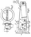
- Fig. 3 is an end view of the valve of Fig. 2 from the inlet side with the butterfly open;
- Fig. 4 is similar to Fig. 3 and shows the butterfly closed;
- Fig. 5 is a plan view of a pneumatically operated EPM valve;
- Fig. 6 is a side view of the EPM valve shown in Fig. 5;
- Fig. 7 is a view on the EPM valve of Fig. 5 from the outlet side.
- Fig. 1 illustrates the difference between a conventional exhaust brake and a reactive exhaust brake.
- The dotted line illustrates the effect of conventional exhaust brake on back pressure (P) with increasing engine gas flow (F); gas flow of course increases with increasing engine speed.
- A conventional exhaust brake includes one or more relatively large holes in the butterfly so that at maximum gas flow (maximum engine speed) the back pressure developed by the exhaust brake does not exceed the maximum design back pressure of the engine - this is illustrated by point c1.
- Accordingly at low gas flow rates, the butterfly holes are too large to generate an effective back pressure, and in the normal operating range of the engine, the back pressure generated may be only 20-50% of the maximum permissible - illustrated by points C2 and C3.
- In contrast, the solid line of Fig. illustrates the operating curve of a reactive exhaust brake according to the invention. The butterfly contains only a relatively small aperture (typically less than one-tenth of the total area of the holes in a conventional exhaust brake butterfly) and thus on application the exhaust brake generates almost maximum back pressure throughout the normal operating range of the engine.
- The exhaust brake of Figs. 2-4 includes a
cylindrical valve body 10 for connection byend flanges 11 to an exhaust tract and within which is a butterfly-type valve 12 mounted upon aspindle 14 to pivot about an axis displaced by a predetermined distance d (typically 3 mm for a valve of up to 5" diameter) from a diameter of thevalve body 10. The direction of gas flow is indicated by arrow D. Rigidly mounted on thebutterfly valve spindle 14 externally of thevalve body 10 is a double endedlever 16, oneend 18 of which is connected to areturn spring 20 anchored at a fixedabutment 21 of amounting plate 19. Theother end 22 oflever 16 is connected via anoverride spring 24 to acontrol cable 26 leading to the vehicle cab (not shown) for operation by the driver. The mounting plate includes anabutment 27 for thecable sheath 28a. - In the illustrated position the
lever 16 is held in abutment with astop 28 by thereturn spring 20, thevalve 12 being in the fully open position and thecontrol cable 26 being relaxed. - In operation the
valve 12 is closed by pulling thecable 26 in the direction ofabutment 27, thecable spring 24 extends, generating a torque which opposes the torque of thereturn spring 20 and the torque generated on thespindle 14 by exhaust gas back pressure. This latter torque is a result of the spindle axis being offset from the centreline of thevalve body 10. - As exhaust gas back pressure reaches the maximum permissible level, the spindle torque due to exhaust pressure increases to a point at which it balances the excess torque of
cable spring 24 overreturn spring 20. At this point the valve is balanced with zero net torque and any further increase in exhaust pressure will tend to open thevalve 12. - The
valve 12 is thus reactive and opens at a pre-set back pressure to prevent engine damage while ensuring that the valve is fully effective as an exhaust brake throughout the normal operating range of the engine. - The
return spring 20 is capable of re-opening thevalve 12 when the closing force is removed, in this case when thecable 26 is relaxed. The offset of thevalve spindle 14 allows the gas pressure to generate an opening torque proportional to the back pressure. - The
valve 12 also includes ahole 29, as illustrated in Fig. 4, or a bypass through the wall of thebody 10, which allows the valve to be used as a warm-up valve to bring the engine up to working temperature. In this mode thevalve 12 is closed when the engine has just been started from cold. The valve imposes a relatively low back pressure on the engine (typically 1 bar) because the engine is running at slow speed (around 800 rpm) and thebleed hole 29 permits a small throughput of exhaust gas. This small back pressure dramatically reduces the time for the engine to reach normal operating temperature, typically from around 80 to 40 minutes. In the event that the engine speed increases, for example if the vehicle driver moves off without releasing thecable 26, the valve will operate as a reactive exhaust brake as described above. Engine damage when used as a warm-up valve is thus prevented. - The valve is designed to prevent back pressure being generated above prescribed levels if the butterfly is closed when the engine RPM, and thus the gas flow, is large enough to generate excessive back pressure, or if the valve is held closed while engine RPM increases above that which would generate an excessive back pressure.
- A similar arrangement could be used when the valve is closed by pneumatic, electric vacuum, hydraulic or any other means.
- In the case of a pneumatically operated butterfly valve it is possible to make use of the return spring within the pneumatic actuator itself. One such embodiment is shown in Figs. 5 to 7. The
butterfly valve 32 andcylindrical valve body 30 withflanges 31, are arranged in substantially the same manner as shown in Figs. 2 to 4. In this embodiment oneend flange 31a is adapted for mounting directly to a turbocharger outlet. Oneend 34 of thelever 36 is connected to anadjustable piston rod 38 of apneumatic actuator 40 held by the actuator return spring against thestop 42 with thebutterfly 32 in the fully open position. Spindle offset is indicated by 'd', and gas flow by arrow D. - The
butterfly 32 is closed by compressed air supplied to theactuator 40 by apressure control valve 44 connected to a source S of compressed air, the air supplied acting against the actuator return spring to generate a closing torque on thebutterfly valve 32 and urge the valve closed. - The pressure of air supplied to the actuator is controlled by the
valve 44 which is set to hold the valve closed against the actuator return spring and the torque generated by the exhaust gas at the prescribed maximum back pressure level. - If the back pressure starts to rise under the action of increased exhaust gas flow an imbalance is created, and the resulting torque combined with the actuator return spring torque overcomes the pneumatic actuator torque so that the valve opens returning the back pressure to the prescribed level.
- The level of back pressure required can be achieved by a combination of butterfly offset, lever length, actuator return spring and the pressure of air supplied to the actuator.
- Another method of giving a suitable actuator load is to dispense with the pressure control valve and vary the actuator return spring or springs. The spring or springs may be adjustable at the actuator or selected to apply a predetermined load to suit a particular application.
Claims (7)
- An exhaust pressure modulation valve comprising a body (10) having an inlet, an outlet, and a passageway between said inlet and outlet, a butterfly (12) pivotable in the body (10) to close communication between said inlet and outlet, said butterfly having a spindle pivot axis (14) and said spindle pivot axis (14) being offset from an axis of symmetry of said passageway such that a resultant torque generated in response to increasing pressure at said inlet tends to open the butterfly (12), said valve further comprising operating means for closing said butterfly and adapted to apply to said spindle pivot axis (14) a closing torque of the same magnitude as said resultant torque generated at a pre-determined pressure at said inlet, and a bleed means (29) from one side of said butterfly (12) to the other comprising an aperture (29) in the butterfly (12), said bleed means (29) being sized to ensure a significant back pressure when said butterfly (12) is in use closed and the flow of gas through said valve is significantly less than the maximum flow of gas through said valve, characterised in that said bleed means (29) have a cross-sectional area not greater than 0.25% of the cross-sectional area of said butterfly (12), wherein the axis of symmetry is on one side of the pivot axis (14), and said bleed aperture (29) in on the other side of the pivot axis (14).
- A valve according to Claim 1 wherein said operating means comprises a lever (16) attached to said spindle (14) and external to said body (10), actuating means being attached to said lever (16) and adapted to apply a closing torque to said spindle (14).
- A valve according to Claim 1 or 2 wherein said lever (16) has one side (18) connected to a return spring (20) thereby to impose an opening torque on said spindle, and the other side (22) connected in series by a control spring (24) to an actuator (26).
- A valve according to Claim 3 wherein said lever (16) is double ended, one end (18) of the lever (16) being connected to said return spring (20) and the other end (22) to said control spring (24).
- A valve according to Claim 3 or Claim 4 wherein said return spring (20) and said control spring (24) are tension springs.
- A valve according to Claim 2 wherein said actuating means comprise a fluid actuator (40) having an internal return spring.
- A valve according to Claim 6 and further comprising an adjustable fluid pressure control valve (44) operable to vary the pressure of fluid admitted to said actuator (40).
Applications Claiming Priority (3)
| Application Number | Priority Date | Filing Date | Title |
|---|---|---|---|
| GB909024644A GB9024644D0 (en) | 1990-11-13 | 1990-11-13 | An exhaust brake |
| GB9024644 | 1990-11-13 | ||
| PCT/GB1991/002004 WO1992008887A1 (en) | 1990-11-13 | 1991-11-13 | Exhaust pressure modulation valve |
Publications (2)
| Publication Number | Publication Date |
|---|---|
| EP0557367A1 EP0557367A1 (en) | 1993-09-01 |
| EP0557367B1 true EP0557367B1 (en) | 1996-10-23 |
Family
ID=10685293
Family Applications (1)
| Application Number | Title | Priority Date | Filing Date |
|---|---|---|---|
| EP91920141A Expired - Lifetime EP0557367B1 (en) | 1990-11-13 | 1991-11-13 | Exhaust pressure modulation valve |
Country Status (7)
| Country | Link |
|---|---|
| US (1) | US5394901A (en) |
| EP (1) | EP0557367B1 (en) |
| JP (1) | JPH06502704A (en) |
| DE (1) | DE69122880T2 (en) |
| ES (1) | ES2093718T3 (en) |
| GB (1) | GB9024644D0 (en) |
| WO (1) | WO1992008887A1 (en) |
Families Citing this family (21)
| Publication number | Priority date | Publication date | Assignee | Title |
|---|---|---|---|---|
| GB9212230D0 (en) * | 1992-06-09 | 1992-07-22 | Wabco Automotive Uk | Exhaust brake and pressure modulation valve |
| GB9312389D0 (en) * | 1993-06-16 | 1993-07-28 | Hersham Valves Ltd | Exhaust brake |
| DE19540060A1 (en) * | 1995-10-27 | 1997-04-30 | Daimler Benz Ag | Engine brake device |
| US5676110A (en) * | 1996-03-14 | 1997-10-14 | Meneely; Vincent Allan | Exhaust brake with offset butterfly and method of reducing back pressure therein |
| SE511633C2 (en) | 1996-11-22 | 1999-11-01 | Volvo Lastvagnar Ab | Fluid driven actuator and use thereof |
| US6085722A (en) * | 1996-12-18 | 2000-07-11 | Caterpillar Inc. | Exhaust restrictor with gear motor actuator and method of controlling same |
| US6179096B1 (en) * | 1997-11-12 | 2001-01-30 | Diesel Engine Retarders, Inc. | Exhaust brake variable bypass circuit |
| CA2455344A1 (en) | 2001-04-20 | 2002-10-31 | Jenara Enterprises Ltd. | Apparatus and control for variable exhaust brake |
| CA2453593C (en) * | 2003-12-16 | 2013-05-28 | Jenara Enterprises Ltd. | Pressure relief exhaust brake |
| CN102094714B (en) * | 2004-11-22 | 2014-01-15 | 雅各布斯车辆系统公司 | Apparatus and method for controlling exhaust pressure |
| DE102008010658B4 (en) * | 2008-02-22 | 2010-08-19 | Knorr-Bremse Systeme für Nutzfahrzeuge GmbH | Exhaust gas control system and emission control method |
| US8157241B2 (en) * | 2008-02-29 | 2012-04-17 | General Electric Company | Methods and apparatus for regulating gas turbine engine fluid flow |
| US7735466B1 (en) * | 2009-06-12 | 2010-06-15 | Jacobs Vehicle Systems, Inc. | Exhaust brake |
| DE102009036914A1 (en) * | 2009-08-11 | 2011-03-10 | Mahle International Gmbh | Stellanordnung for adjusting a valve |
| US8375982B2 (en) * | 2009-09-28 | 2013-02-19 | The United States Of America, As Represented By The Administrator Of The U.S. Environmental Protection Agency | Hydraulic circuit and manifold with multifunction valve |
| DE102010020049A1 (en) * | 2010-05-11 | 2011-11-17 | Daimler Ag | Damming device of an internal combustion engine |
| US20130228230A1 (en) * | 2012-03-02 | 2013-09-05 | Field Specialties, Inc. | Vacuum actuated valve |
| KR101745068B1 (en) * | 2015-01-30 | 2017-06-08 | 현대자동차주식회사 | Exhaust brake |
| AT518258B1 (en) * | 2016-02-19 | 2017-09-15 | Avl List Gmbh | METHOD FOR OPERATING AN INTERNAL COMBUSTION ENGINE |
| US20180334953A1 (en) * | 2017-05-16 | 2018-11-22 | Borgwarner Inc. | Linear Actuator Cable Linkage |
| US11639703B1 (en) * | 2022-06-21 | 2023-05-02 | Garrett Transportation I Inc. | System and method using secondary air pump for secondary air injection into turbocharged internal combustion engine exhaust and for transiently augmenting engine boost pressure, including means for supressing surge of the secondary air pump |
Family Cites Families (19)
| Publication number | Priority date | Publication date | Assignee | Title |
|---|---|---|---|---|
| US2428708A (en) * | 1943-10-22 | 1947-10-07 | Heftler Paul | Turbosupercharger |
| GB783900A (en) * | 1955-02-25 | 1957-10-02 | Thomas Ash & Company Ltd | Improvements in or relating to exhaust brakes for vehicles |
| US2947392A (en) * | 1956-10-03 | 1960-08-02 | Mack Trucks | Control system for exhaust brake |
| FR1198272A (en) * | 1957-07-06 | 1959-12-07 | Maschf Augsburg Nuernberg Ag | Exhaust brake for internal combustion engines of vehicles |
| US3153427A (en) * | 1961-09-14 | 1964-10-20 | Aero Flow Dynamics Inc | Butterfly check valve |
| GB1043865A (en) * | 1962-07-12 | 1966-09-28 | Michael Guillermo May | Improvements in and relating to internal combustion engines |
| GB1044282A (en) * | 1962-08-07 | 1966-09-28 | Dewandre Co Ltd C | Improvements in or relating to exhaust braking apparatus for motor vehicles |
| US3625249A (en) * | 1970-02-26 | 1971-12-07 | James F Karr | Eccentric damper-type valve for controlled action |
| DE2505675A1 (en) * | 1975-02-11 | 1976-08-19 | Daimler Benz Ag | EXHAUST BRAKE FOR VEHICLES |
| DE2648676A1 (en) * | 1976-03-11 | 1977-09-22 | Josef V Illichmann | Engine brake using exhaust gas back pressure - has servo actuated flap which pivots into recess out of gas flow |
| US4111166A (en) * | 1977-02-07 | 1978-09-05 | Caterpillar Tractor Co. | Engine mounted exhaust brake |
| US4220008A (en) * | 1978-12-28 | 1980-09-02 | Cummins Engine Company | Exhaust brake modulating control system |
| US4254752A (en) * | 1979-09-17 | 1981-03-10 | Stewart & Stevenson Services, Inc. | Method of and apparatus for improving operation of a diesel engine at light loads |
| DE3211920A1 (en) * | 1982-03-31 | 1983-10-13 | Klöckner-Humboldt-Deutz AG, 5000 Köln | Device on an exhaust brake |
| GB8425657D0 (en) * | 1984-10-10 | 1984-11-14 | Austin Rover Group | Exhaust system |
| DE3533393A1 (en) * | 1985-09-19 | 1987-03-26 | Alfred Schmidt | CONSTRUCTION PRESSURE LIMIT WITH SAFETY VALVE |
| US4835963A (en) * | 1986-08-28 | 1989-06-06 | Allied-Signal Inc. | Diesel engine particulate trap regeneration system |
| DE3743569A1 (en) * | 1987-12-22 | 1989-07-13 | Alfred Schmidt | SLIDE VALVE WITH QUANTITY CONTROL |
| DE3835545A1 (en) * | 1988-10-19 | 1990-04-26 | Man Nutzfahrzeuge Ag | ENGINE BRAKE IN EXHAUST MANIFOLD |
-
1990
- 1990-11-13 GB GB909024644A patent/GB9024644D0/en active Pending
-
1991
- 1991-11-13 DE DE69122880T patent/DE69122880T2/en not_active Expired - Lifetime
- 1991-11-13 ES ES91920141T patent/ES2093718T3/en not_active Expired - Lifetime
- 1991-11-13 JP JP3518389A patent/JPH06502704A/en active Pending
- 1991-11-13 US US08/050,292 patent/US5394901A/en not_active Expired - Lifetime
- 1991-11-13 WO PCT/GB1991/002004 patent/WO1992008887A1/en not_active Ceased
- 1991-11-13 EP EP91920141A patent/EP0557367B1/en not_active Expired - Lifetime
Also Published As
| Publication number | Publication date |
|---|---|
| DE69122880D1 (en) | 1996-11-28 |
| WO1992008887A1 (en) | 1992-05-29 |
| ES2093718T3 (en) | 1997-01-01 |
| EP0557367A1 (en) | 1993-09-01 |
| DE69122880T2 (en) | 1997-04-03 |
| JPH06502704A (en) | 1994-03-24 |
| US5394901A (en) | 1995-03-07 |
| GB9024644D0 (en) | 1991-01-02 |
Similar Documents
| Publication | Publication Date | Title |
|---|---|---|
| US5394901A (en) | Exhaust pressure modulation valve | |
| US6179096B1 (en) | Exhaust brake variable bypass circuit | |
| US6152853A (en) | Vehicle exhaust brake and control system | |
| US6652414B1 (en) | Vehicle engine brake and control system | |
| US6109027A (en) | Exhaust restriction device | |
| EP0536284B1 (en) | An exhaust modulator | |
| US8011347B2 (en) | Apparatus and method for pressure relief in an exhaust brake | |
| US4060063A (en) | Throttle positioner | |
| US5435347A (en) | Exhaust systems for motorized vehicles | |
| US4922872A (en) | Engine brake system | |
| US3996904A (en) | Throttle positioner | |
| EP1841961B1 (en) | Apparatus and method for controlling exhaust pressure | |
| EP0578373B1 (en) | Exhaust brake and pressure modulation valve | |
| RU2218470C2 (en) | Decelerator built into exhaust system of vehicle powered by internal combustion engine | |
| US5036811A (en) | Four-stroke internal-combustion engine | |
| SU856395A3 (en) | Device for controlling throttle valve of i.c. engine | |
| EP0537120B1 (en) | An intake manifold unit for fuel injection internal combustion engines | |
| EP0728920B1 (en) | Method and arrangement for control of an exhaust brake in a combustion engine | |
| JPH0216331A (en) | Turbocharger control device | |
| JP2524058Y2 (en) | Exhaust brake device | |
| KR960000196Y1 (en) | Brake system for loader | |
| JPS63120829A (en) | Driving gear for throttle valve | |
| KR0142595B1 (en) | Engine brake device for turbocharged vehicle | |
| JPS6134578B2 (en) | ||
| JPS5833240Y2 (en) | Carburetor throttle valve control device for vehicle engines with automatic transmissions |
Legal Events
| Date | Code | Title | Description |
|---|---|---|---|
| PUAI | Public reference made under article 153(3) epc to a published international application that has entered the european phase |
Free format text: ORIGINAL CODE: 0009012 |
|
| 17P | Request for examination filed |
Effective date: 19930525 |
|
| AK | Designated contracting states |
Kind code of ref document: A1 Designated state(s): DE ES FR GB IT SE |
|
| 17Q | First examination report despatched |
Effective date: 19940324 |
|
| GRAG | Despatch of communication of intention to grant |
Free format text: ORIGINAL CODE: EPIDOS AGRA |
|
| GRAH | Despatch of communication of intention to grant a patent |
Free format text: ORIGINAL CODE: EPIDOS IGRA |
|
| RAP1 | Party data changed (applicant data changed or rights of an application transferred) |
Owner name: WABCO AUTOMOTIVE U.K. LIMITED |
|
| GRAH | Despatch of communication of intention to grant a patent |
Free format text: ORIGINAL CODE: EPIDOS IGRA |
|
| GRAA | (expected) grant |
Free format text: ORIGINAL CODE: 0009210 |
|
| ITF | It: translation for a ep patent filed | ||
| AK | Designated contracting states |
Kind code of ref document: B1 Designated state(s): DE ES FR GB IT SE |
|
| REF | Corresponds to: |
Ref document number: 69122880 Country of ref document: DE Date of ref document: 19961128 |
|
| ET | Fr: translation filed | ||
| REG | Reference to a national code |
Ref country code: ES Ref legal event code: FG2A Ref document number: 2093718 Country of ref document: ES Kind code of ref document: T3 |
|
| PLBE | No opposition filed within time limit |
Free format text: ORIGINAL CODE: 0009261 |
|
| STAA | Information on the status of an ep patent application or granted ep patent |
Free format text: STATUS: NO OPPOSITION FILED WITHIN TIME LIMIT |
|
| 26N | No opposition filed | ||
| REG | Reference to a national code |
Ref country code: GB Ref legal event code: IF02 |
|
| REG | Reference to a national code |
Ref country code: GB Ref legal event code: 732E |
|
| REG | Reference to a national code |
Ref country code: FR Ref legal event code: TP |
|
| REG | Reference to a national code |
Ref country code: ES Ref legal event code: PC2A |
|
| PGFP | Annual fee paid to national office [announced via postgrant information from national office to epo] |
Ref country code: FR Payment date: 20101112 Year of fee payment: 20 |
|
| PGFP | Annual fee paid to national office [announced via postgrant information from national office to epo] |
Ref country code: DE Payment date: 20101119 Year of fee payment: 20 |
|
| PGFP | Annual fee paid to national office [announced via postgrant information from national office to epo] |
Ref country code: GB Payment date: 20101105 Year of fee payment: 20 Ref country code: SE Payment date: 20101112 Year of fee payment: 20 Ref country code: IT Payment date: 20101126 Year of fee payment: 20 |
|
| PGFP | Annual fee paid to national office [announced via postgrant information from national office to epo] |
Ref country code: ES Payment date: 20101126 Year of fee payment: 20 |
|
| REG | Reference to a national code |
Ref country code: DE Ref legal event code: R071 Ref document number: 69122880 Country of ref document: DE |
|
| REG | Reference to a national code |
Ref country code: DE Ref legal event code: R071 Ref document number: 69122880 Country of ref document: DE |
|
| REG | Reference to a national code |
Ref country code: GB Ref legal event code: PE20 Expiry date: 20111112 |
|
| REG | Reference to a national code |
Ref country code: SE Ref legal event code: EUG |
|
| PG25 | Lapsed in a contracting state [announced via postgrant information from national office to epo] |
Ref country code: GB Free format text: LAPSE BECAUSE OF EXPIRATION OF PROTECTION Effective date: 20111112 |
|
| PG25 | Lapsed in a contracting state [announced via postgrant information from national office to epo] |
Ref country code: DE Free format text: LAPSE BECAUSE OF EXPIRATION OF PROTECTION Effective date: 20111114 |
|
| REG | Reference to a national code |
Ref country code: ES Ref legal event code: FD2A Effective date: 20130724 |
|
| PG25 | Lapsed in a contracting state [announced via postgrant information from national office to epo] |
Ref country code: ES Free format text: LAPSE BECAUSE OF EXPIRATION OF PROTECTION Effective date: 20111114 |