EP0555945B1 - A capacity control mechanism for scroll-type compressor - Google Patents
A capacity control mechanism for scroll-type compressor Download PDFInfo
- Publication number
- EP0555945B1 EP0555945B1 EP93250040A EP93250040A EP0555945B1 EP 0555945 B1 EP0555945 B1 EP 0555945B1 EP 93250040 A EP93250040 A EP 93250040A EP 93250040 A EP93250040 A EP 93250040A EP 0555945 B1 EP0555945 B1 EP 0555945B1
- Authority
- EP
- European Patent Office
- Prior art keywords
- hole
- suction
- holes
- piston valve
- chamber
- Prior art date
- Legal status (The legal status is an assumption and is not a legal conclusion. Google has not performed a legal analysis and makes no representation as to the accuracy of the status listed.)
- Expired - Lifetime
Links
Images


Classifications
-
- F—MECHANICAL ENGINEERING; LIGHTING; HEATING; WEAPONS; BLASTING
- F04—POSITIVE - DISPLACEMENT MACHINES FOR LIQUIDS; PUMPS FOR LIQUIDS OR ELASTIC FLUIDS
- F04C—ROTARY-PISTON, OR OSCILLATING-PISTON, POSITIVE-DISPLACEMENT MACHINES FOR LIQUIDS; ROTARY-PISTON, OR OSCILLATING-PISTON, POSITIVE-DISPLACEMENT PUMPS
- F04C18/00—Rotary-piston pumps specially adapted for elastic fluids
- F04C18/02—Rotary-piston pumps specially adapted for elastic fluids of arcuate-engagement type, i.e. with circular translatory movement of co-operating members, each member having the same number of teeth or tooth-equivalents
-
- F—MECHANICAL ENGINEERING; LIGHTING; HEATING; WEAPONS; BLASTING
- F04—POSITIVE - DISPLACEMENT MACHINES FOR LIQUIDS; PUMPS FOR LIQUIDS OR ELASTIC FLUIDS
- F04C—ROTARY-PISTON, OR OSCILLATING-PISTON, POSITIVE-DISPLACEMENT MACHINES FOR LIQUIDS; ROTARY-PISTON, OR OSCILLATING-PISTON, POSITIVE-DISPLACEMENT PUMPS
- F04C28/00—Control of, monitoring of, or safety arrangements for, pumps or pumping installations specially adapted for elastic fluids
- F04C28/10—Control of, monitoring of, or safety arrangements for, pumps or pumping installations specially adapted for elastic fluids characterised by changing the positions of the inlet or outlet openings with respect to the working chamber
- F04C28/12—Control of, monitoring of, or safety arrangements for, pumps or pumping installations specially adapted for elastic fluids characterised by changing the positions of the inlet or outlet openings with respect to the working chamber using sliding valves
Definitions
- This invention relates to an improvement of a capacity control mechanism for a scroll-type compressor.
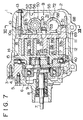
- FIG.7 One example of the scroll-type compressor of the related art is shown in Figs.7 through 13.
- reference numeral 1 denotes a housing.
- the housing 1 comprises a cup-shaped body 2, a front end plate 4 fastened to the cup-shaped body 2 with bolts 3, and a cylindrical member 6 fastened to the front end plate 4 with bolts 5.
- a main shaft 7 passing through the cylindrical member 6 is rotatably supported by the housing 1 via bearings 8 and 9.
- the housing 1 incorporates a fixed scroll 10 and a rotary scroll 14.
- the fixed scroll 10 has an end plate 11 and a spiral lap 12 installed on the inner surface of the end plate 11.
- a discharge port 29 is disposed at the center of the end plate 11 and a pair of bypass ports 33a, 33b communicating with compression chambers 19a and 19b during compression are also disposed.
- the rotary scroll has an end plate 15 and a spiral lap 16 installed on the inner surface of the end plate 15.
- the shape of the spiral lap 16 is substantially the same as that of the spiral lap 12 of the fixed scroll 10.
- the rotary scroll 14 and the fixed scroll 10 are off-centered mutually by the radius of revolution and engaged with each other at a shifted angle of 180° as shown in the figure.
- a tip seal 17 embedded in the tip end of spiral lap 12 is in contact with the inner surface of the end plate 15, while the tip seal 18 embedded in the tip end of spiral lap 16 is in contact with the inner surface of the end plate 11.
- the side surfaces of the spiral laps 12 and 16 are in linear contact with each other at a plurality of places, and a plurality of compression chambers 19a, 19b which are symmetric with respect to the center of spiral are formed.
- a drive bushing 21 is rotatably fitted via a bearing 23.
- an eccentric bore 24 made in the drive bushing 21 an eccentric pin 25 extending eccentrically from the inner end of the main shaft 7 is rotatably inserted.
- a balance weight 27 To this drive bushing 21 is installed a balance weight 27.
- a rotation inhibiting mechanism 40 which is also used as a thrust bearing, is disposed.
- a capacity control block 50 is installed in such a manner as to be in contact with the outer surface of the end plate 11 of the fixed scroll 10.
- the convex portion 51 of the capacity control block 50 is engaged with the concave portion 10a disposed on the fixed scroll 10.
- the capacity control block 50 is fixed together with the fixed scroll 10 in the housing 1 with bolts 13 which pass through the cup-shaped body 2 and bolt holes 52 made in the capacity control block 50, and are screwed in the fixed scroll 10.
- the rear outer peripheral surface of the capacity control block 50 is in contact with the inner peripheral surface of the cup-shaped body 2, by which the inside of the housing 1 is divided into a suction chamber 28 and a discharge cavity 31.
- a discharge hole 53 communicating with the discharge port 29 is provided.
- the discharge hole 53 is opened/closed by a discharge valve 30 which is fastened together with a retainer 35 to the outer surface of control block 50 with a bolt 36, as shown in Fig.11.
- a blind hole shaped cylinder 54 is provided on one side of the discharge hole 53, and a blind hole shaped cavity 55 is provided in parallel to the cylinder 54 on the other side thereof.
- the open ends of the cylinder 54 and the cavity 55 communicate with the suction chamber 28.
- a cup-shaped piston valve 56 is incorporated sealingly and slidably.
- a control pressure chamber 80 is defined, and a suction-side chamber 81 defined on the other end side thereof communicates with the suction chamber 28.
- the piston valve 56 is pushed against the bottom of cylinder 54 by a coil spring 83 interposed between the piston valve 56 and a spring shoe 82.
- An annular groove 93 disposed at the outer peripheral surface of the piston valve 56 always communicates with the suction-side chamber 81 via a plurality of holes 94.
- a control valve 58 is installed in the cavity 55.
- an atmospheric pressure chamber 63 communicates with the atmosphere outside the housing 1 via a through hole 67 and a not illustrated connecting pipe.
- the low pressure chamber 64 communicates with the suction chamber 28 via a through hole 68.
- the control pressure chamber 65 communicates with the control pressure chamber 80 via a through hole 69, a groove 70, and a through hole 71 as shown in Fig.8.
- the high pressure chamber 66 communicates with the discharge cavity 31 via a through hole 72 as shown in Fig.7.
- the control valve 58 incorporates a valve mechanism. This valve mechanism senses high pressure HP in the discharge cavity 31 and low pressure LP in the suction chamber 28, and produces control pressure AP, which is an intermediate pressure between the high pressure and the low pressure and can be represented as a linear function of low pressure LP.
- grooves 70, 90, 91 and recesses 86, 87a, 87b, 88 are formed on the inner surface of the capacity control block 50.
- a land portion 57 surrounding the recesses 86, 87a, 87b, and 88 is provided with a seal groove 84, in which a seal material 85 is installed.
- the recesses 86, 87a, 87b and 88 are divided from each other.
- the recess 87a is divided from the recess 87b by a partition 97.
- the recess 86 communicates with the control pressure chambers 65 and 80 via the groove 70 and through holes 69, 71.
- the recesses 87a, 87b communicate with the compression chamber 19a, 19b during compression via bypass ports 33a, 33b disposed in the end plate 11, respectively, as shown in Fig.7, and communicate with the suction-side chamber 81 via first through holes 89a, 89b provided in the cylinder 54 as shown in Fig.12.
- the recess 88 communicates with the discharge hole 53 via grooves 90, 91, and communicates with the suction-side chamber 81 via a second through hole 92 provided in the cylinder 54, the annular groove 93 provided in the outer peripheral surface of the piston valve 56, and holes 94.
- the bypass ports 33a, 33b are located at a position communicating with the compression chambers 19a, 19b until the suction of gas is completed, the compression stroke starts, and the capacity is reduced to 50%.
- the rotary scroll 14 When the main shaft 7 is rotated, the rotary scroll 14 is driven via a rotation drive mechanism consisting of the eccentric pin 25, the drive bushing 21, the boss 22 and the like.
- the rotary scroll 14 revolves on a circular trajectory with a radius of offset between the main shaft 7 and the eccentric pin 25 while its rotation is inhibited by the rotation inhibiting mechanism 40.
- the linear contact portion between the spiral laps 12 and 16 gradually moves toward the center of spiral; as a result, the compression chambers 19a, 19b move toward the center of spiral while their volumes being reduced.
- a gas flowing into the suction chamber 28 through a not illustrated suction port is introduced into the compression chambers 19a, 19b through the outer peripheral end opening of the spiral laps 12 and 16.
- the gas reaches the central portion while being compressed, passes through the discharge port 29, and is discharged into the discharge cavity 31 by pushing the discharge valve 30 to open it. Then, the gas flows out through a not illustrated discharge port.
- control valve 58 When the capacity of the compressor is set to 0%, the control valve 58 develops a control pressure AP of low value.
- This control pressure AP is introduced into the control pressure chamber 80 via the through hole 69, the groove 70, and the through hole 71.
- the piston valve 56 since its pressure is low, the piston valve 56 is pushed by the restoring force of coil spring 83 and is positioned as shown in Fig.12.
- the first through holes 89a, 89b and the second through hole 92 are all opened, so that the gas being compressed in the compression chambers 19a, 19b enters the suction-side chamber 81 via the bypass ports 33a, 33b, recesses 87a, 87b, and the first through holes 89a, 89b.
- the compressed gas reaching the center of spiral enters the suction-side chamber 81 via the discharge port 29, the discharge hole 53, the recess 88, the grooves 90, 91, the second through hole 92, the groove 93, and the holes 94. These two gases join in the suction-side chamber 81, and are discharged into the suction chamber 28. As a result, the capacity of compressor becomes zero.
- the control valve 58 develops a control pressure AP of high value .
- This control pressure AP of high value enters the control pressure chamber 80, and pushes the end face of the piston valve 56.
- the piston valve 56 retracts against the tension force of the coil spring 83, and is located at the position where its outer end abuts the spring shoe as shown in Fig.8.
- the first through holes 89a, 89b and the second through hole 92 are closed by the piston valve 56, so that the compressed gas reaching the center of spiral passes through the discharge port 29 and the discharge hole 53, pushes the discharge valve 30 to open it, and is discharged into the discharge cavity 31.
- control valve 58 develops a control pressure AP corresponding to the reduction ratio.
- this control pressure AP acts on the end face of piston valve 56 via the control pressure chamber 80, the piston valve 56 stops at the position where the pushing force of control pressure AP balances with the tension force of the coil spring 83. Therefore, when the control pressure AP becomes low, only the first through holes 89a, 89b are opened. The gas being compressed in the compression chamber 19a, 19b is discharged into the suction chamber 28 in the amount corresponding to the degree of opening of the first through holes 89a, 89b, and accordingly the capacity of compressor is decreased.
- EP-A-354867 discloses such a scroll compressor including the features of the preamble of claim 1.
- the conventional capacity control mechanism described above has the following disadvantages:
- the gas being compressed flows into the suction-side chamber 81 via the first through holes 89a, 89b, thereby the pressure in the suction-side chamber 81 changes suddenly. Therefore, a hunting phenomenon, in which the stationary state of the piston valve 56 is not stabilized, occurs; as a result, the operation of compressor becomes unstable, and unusual noise is generated.
- An object of the present invention is to provide a capacity control mechanism for a scroll-type compressor which provides stabilized operation and prevents the generation of unusual noise.
- a capacity control mechanism for a scroll-type compressor comprising a control pressure chamber in which a control pressure developed by a control valve is introduced to one side of a piston valve by fitting the piston valve sealingly and slidably in a cylinder, a suction-side chamber which communicates with a suction chamber on the other side of the piston valve, a first through hole which introduces the gas being compressed in the cylinder to the suction-side chamber, and a second through hole which introduces the compressed gas to the suction-side chamber, wherein the first and second through holes are opened in that order by the movement of the piston valve in the cylinder along with the decrease in the control pressure
- the capacity control mechanism for a scroll-type compressor is so constructed that the first through hole is shaped so that the opening area at the start of the opening increases gradually along with the movement of the piston valve.
- an auxiliary through hole which has a smaller opening area than the first through hole and is opened by the piston valve before the first through hole is opened is provided to introduce the gas being compressed into the suction-side chamber.
- the piston valve moves along with the decrease in control pressure, so that the gas being compressed gradually enters the suction-side chamber. Therefore, the variation in pressure in the suction-side chamber is decreased and the hunting of piston valve is prevented.
- first through holes 95a, 95b are provided in place of the first through holes 89a and 89b shown in Fig.12. These first through holes 95a, 95b take a triangular shape whose vertex lies in the direction of the open end of cylinder 54. These two first through holes 95a, 95b are arranged in parallel so as to open simultaneously by the movement of the piston valve 56. Therefore, at the start of the opening, the opening area increases gradually along with the movement of the piston valve 56. Also, in the cylinder 54 are provided auxiliary through holes 96a, 96b, which are opened by the piston valve 56 before the first through holes 95a, 95b are opened.
- auxiliary through holes 96a, 96b have a smaller opening area than the first through holes 95a, 95b, and is of a circular shape.
- the auxiliary through holes 96a, 96b are arranged in parallel so as to open simultaneously by the movement of the piston valve 56.
- the auxiliary through holes 96a, 96b communicate with a suction-side chamber 81, like a second through hole 92, via an annular groove 93 and a plurality of holes 94 made in the outer peripheral surface of the piston valve 56.
- the other constitution is the same as that of the conventional mechanism shown in Figs.7 through 13, and the same reference numerals are applied to the corresponding elements.
- the control pressure AP developed by a control valve 58 decreases, and this control pressure AP is introduced from a control pressure chamber 65 to a control pressure chamber 80.
- the piston valve 56 is pushed by the restoring force of the coil spring 83, and moves to the right from the position shown in Fig.1.
- the auxiliary through holes 96a, 96b are first opened by aligning with the annular groove 93 as shown in Fig.2(a), and then the first through holes 95a, 95b are opened and expanded gradually as shown in Fig.2(b).
- auxiliary through holes 96a, 96b When the auxiliary through holes 96a, 96b are opened, the gas being compressed in compression chambers 19a, 19b is discharged into a suction chamber 28 via bypass ports 33a, 33b, recesses 87a, 87b, the auxiliary through holes 96a, 96b, the annular groove 93, holes 94, and the suction-side chamber 81.
- the first through holes 95a, 95b are opened, the gas being compressed is discharged into the suction chamber 28 via the first through holes 95a, 95b, and the suction-side chamber 81.
- the gas being compressed flows first into the suction-side chamber 81 via the auxiliary through holes 96a, 96b having a small opening area, then flows into the suction-side chamber 81 via the first through holes 95a, 95b. Since the gas being compressed flows gradually into the suction-side chamber 81, the variation in pressure in the suction-side chamber 81 decreases, thereby the hunting of the piston valve 56 being prevented.
- the second through hole 92 aligns with the annular groove 93 as shown in Fig.2(c), by which the compressed gas in a discharge port 29 is returned to the suction-side chamber 81 via a discharge hole 53, a recess 88, grooves 90, 91, the second through hole 92, the annular groove 93, and the holes 94.
- first through holes 95a, 95b are formed into a triangular shape and the second through holes 96a, 96b are provided in the above-described embodiment, either the first through holes 95a, 95b or the second through holes 96a, 96b are required as shown in Figs.3 and 4 in order to attain the object of the present invention. Also, although the first through holes 95a, 95b is formed into a triangular shape, they may be formed as shown in Fig.5 or Fig.6.
- the variation in pressure in the suction-side chamber can be decreased because the auxiliary through holes having a small opening area open before the first through holes open. Therefore, the hunting of piston valve can be prevented, so that the generation of unusual noise can be prevented and the compressor can be operated stably.
- the first through holes are shaped so that the opening area at the start of the opening increases gradually along with the movement of the piston valve, the variation in pressure in the suction-side chamber at the start of opening of the first through holes can be further decreased.
Landscapes
- Engineering & Computer Science (AREA)
- Mechanical Engineering (AREA)
- General Engineering & Computer Science (AREA)
- Rotary Pumps (AREA)
- Applications Or Details Of Rotary Compressors (AREA)
Applications Claiming Priority (2)
| Application Number | Priority Date | Filing Date | Title |
|---|---|---|---|
| JP54162/92 | 1992-02-06 | ||
| JP4054162A JP2831193B2 (ja) | 1992-02-06 | 1992-02-06 | スクロール型圧縮機の容量制御機構 |
Publications (2)
| Publication Number | Publication Date |
|---|---|
| EP0555945A1 EP0555945A1 (en) | 1993-08-18 |
| EP0555945B1 true EP0555945B1 (en) | 1995-11-15 |
Family
ID=12962856
Family Applications (1)
| Application Number | Title | Priority Date | Filing Date |
|---|---|---|---|
| EP93250040A Expired - Lifetime EP0555945B1 (en) | 1992-02-06 | 1993-02-03 | A capacity control mechanism for scroll-type compressor |
Country Status (8)
| Country | Link |
|---|---|
| US (1) | US5356271A (ko) |
| EP (1) | EP0555945B1 (ko) |
| JP (1) | JP2831193B2 (ko) |
| KR (1) | KR960009865B1 (ko) |
| CN (1) | CN1031010C (ko) |
| AU (1) | AU655706B2 (ko) |
| CA (1) | CA2088824C (ko) |
| DE (1) | DE69300778T2 (ko) |
Families Citing this family (42)
| Publication number | Priority date | Publication date | Assignee | Title |
|---|---|---|---|---|
| US5451146A (en) * | 1992-04-01 | 1995-09-19 | Nippondenso Co., Ltd. | Scroll-type variable-capacity compressor with bypass valve |
| JPH08151991A (ja) * | 1994-11-29 | 1996-06-11 | Sanden Corp | 可変容量型スクロール圧縮機 |
| US5551846A (en) * | 1995-12-01 | 1996-09-03 | Ford Motor Company | Scroll compressor capacity control valve |
| JP3731287B2 (ja) | 1997-05-12 | 2006-01-05 | 松下電器産業株式会社 | 容量制御スクロール圧縮機 |
| JPH11148480A (ja) * | 1997-11-14 | 1999-06-02 | Mitsubishi Heavy Ind Ltd | 圧縮機 |
| EP0924429B1 (en) * | 1997-12-18 | 2003-08-13 | Mitsubishi Heavy Industries, Ltd. | Scroll compressor |
| JP2001153043A (ja) * | 1999-12-01 | 2001-06-05 | Sanden Corp | 容量可変型斜板式圧縮機 |
| JP4094937B2 (ja) | 2001-11-19 | 2008-06-04 | 三星電子株式会社 | モニタ装置 |
| KR100465792B1 (ko) * | 2002-07-06 | 2005-01-13 | 삼성전자주식회사 | 디스플레이장치 |
| KR100630969B1 (ko) * | 2002-08-24 | 2006-10-02 | 삼성전자주식회사 | 디스플레이장치 |
| US6884042B2 (en) * | 2003-06-26 | 2005-04-26 | Scroll Technologies | Two-step self-modulating scroll compressor |
| JP4483236B2 (ja) * | 2003-09-01 | 2010-06-16 | オムロン株式会社 | 無線端末位置検出装置及び無線端末位置検出方法 |
| US7967583B2 (en) * | 2008-05-30 | 2011-06-28 | Emerson Climate Technologies, Inc. | Compressor having capacity modulation system |
| US7976295B2 (en) * | 2008-05-30 | 2011-07-12 | Emerson Climate Technologies, Inc. | Compressor having capacity modulation system |
| EP2307728B1 (en) * | 2008-05-30 | 2016-08-10 | Emerson Climate Technologies, Inc. | Compressor having output adjustment assembly including piston actuation |
| WO2009155105A2 (en) * | 2008-05-30 | 2009-12-23 | Emerson Climate Technologies, Inc. | Compressor having capacity modulation system |
| CN102588277B (zh) | 2008-05-30 | 2014-12-10 | 艾默生环境优化技术有限公司 | 具有容量调节系统的压缩机 |
| US7976296B2 (en) * | 2008-12-03 | 2011-07-12 | Emerson Climate Technologies, Inc. | Scroll compressor having capacity modulation system |
| US7988433B2 (en) * | 2009-04-07 | 2011-08-02 | Emerson Climate Technologies, Inc. | Compressor having capacity modulation assembly |
| US8616014B2 (en) | 2009-05-29 | 2013-12-31 | Emerson Climate Technologies, Inc. | Compressor having capacity modulation or fluid injection systems |
| US8568118B2 (en) * | 2009-05-29 | 2013-10-29 | Emerson Climate Technologies, Inc. | Compressor having piston assembly |
| US8517703B2 (en) * | 2010-02-23 | 2013-08-27 | Emerson Climate Technologies, Inc. | Compressor including valve assembly |
| US9249802B2 (en) | 2012-11-15 | 2016-02-02 | Emerson Climate Technologies, Inc. | Compressor |
| US9651043B2 (en) | 2012-11-15 | 2017-05-16 | Emerson Climate Technologies, Inc. | Compressor valve system and assembly |
| US9435340B2 (en) | 2012-11-30 | 2016-09-06 | Emerson Climate Technologies, Inc. | Scroll compressor with variable volume ratio port in orbiting scroll |
| US9127677B2 (en) | 2012-11-30 | 2015-09-08 | Emerson Climate Technologies, Inc. | Compressor with capacity modulation and variable volume ratio |
| US9739277B2 (en) | 2014-05-15 | 2017-08-22 | Emerson Climate Technologies, Inc. | Capacity-modulated scroll compressor |
| US9989057B2 (en) | 2014-06-03 | 2018-06-05 | Emerson Climate Technologies, Inc. | Variable volume ratio scroll compressor |
| US9790940B2 (en) | 2015-03-19 | 2017-10-17 | Emerson Climate Technologies, Inc. | Variable volume ratio compressor |
| US10378540B2 (en) | 2015-07-01 | 2019-08-13 | Emerson Climate Technologies, Inc. | Compressor with thermally-responsive modulation system |
| CN207377799U (zh) | 2015-10-29 | 2018-05-18 | 艾默生环境优化技术有限公司 | 压缩机 |
| US10801495B2 (en) | 2016-09-08 | 2020-10-13 | Emerson Climate Technologies, Inc. | Oil flow through the bearings of a scroll compressor |
| US10890186B2 (en) | 2016-09-08 | 2021-01-12 | Emerson Climate Technologies, Inc. | Compressor |
| US10753352B2 (en) | 2017-02-07 | 2020-08-25 | Emerson Climate Technologies, Inc. | Compressor discharge valve assembly |
| US11022119B2 (en) | 2017-10-03 | 2021-06-01 | Emerson Climate Technologies, Inc. | Variable volume ratio compressor |
| US10962008B2 (en) | 2017-12-15 | 2021-03-30 | Emerson Climate Technologies, Inc. | Variable volume ratio compressor |
| CN108386357B (zh) * | 2018-04-18 | 2024-05-28 | 北京燕都碧城科技有限公司 | 一种单螺杆压缩机防液击装置 |
| CN108386356B (zh) * | 2018-04-18 | 2024-05-28 | 北京燕都碧城科技有限公司 | 一种移动式单螺杆压缩机 |
| US10995753B2 (en) | 2018-05-17 | 2021-05-04 | Emerson Climate Technologies, Inc. | Compressor having capacity modulation assembly |
| US11656003B2 (en) | 2019-03-11 | 2023-05-23 | Emerson Climate Technologies, Inc. | Climate-control system having valve assembly |
| US11655813B2 (en) | 2021-07-29 | 2023-05-23 | Emerson Climate Technologies, Inc. | Compressor modulation system with multi-way valve |
| US11846287B1 (en) | 2022-08-11 | 2023-12-19 | Copeland Lp | Scroll compressor with center hub |
Family Cites Families (6)
| Publication number | Priority date | Publication date | Assignee | Title |
|---|---|---|---|---|
| DE3617397A1 (de) * | 1986-05-23 | 1987-11-26 | Wankel Gmbh | Steuerung eines rotationskolbenkompressors |
| JPH073235B2 (ja) * | 1986-10-23 | 1995-01-18 | 松下電器産業株式会社 | 能力制御コンプレツサ |
| JPH0794832B2 (ja) * | 1988-08-12 | 1995-10-11 | 三菱重工業株式会社 | 回転式圧縮機 |
| JP2796427B2 (ja) * | 1990-11-14 | 1998-09-10 | 三菱重工業株式会社 | スクロール型圧縮機 |
| CA2052350C (en) * | 1990-11-14 | 2000-01-18 | Takayuki Iio | Scroll type compressor |
| JP2846106B2 (ja) * | 1990-11-16 | 1999-01-13 | 三菱重工業株式会社 | スクロール型圧縮機 |
-
1992
- 1992-02-06 JP JP4054162A patent/JP2831193B2/ja not_active Expired - Fee Related
-
1993
- 1993-02-03 EP EP93250040A patent/EP0555945B1/en not_active Expired - Lifetime
- 1993-02-03 KR KR1019930001427A patent/KR960009865B1/ko not_active IP Right Cessation
- 1993-02-03 DE DE69300778T patent/DE69300778T2/de not_active Expired - Fee Related
- 1993-02-04 US US08/013,422 patent/US5356271A/en not_active Expired - Lifetime
- 1993-02-04 CA CA002088824A patent/CA2088824C/en not_active Expired - Fee Related
- 1993-02-05 AU AU32843/93A patent/AU655706B2/en not_active Ceased
- 1993-02-06 CN CN93100823A patent/CN1031010C/zh not_active Expired - Fee Related
Also Published As
| Publication number | Publication date |
|---|---|
| CN1075192A (zh) | 1993-08-11 |
| EP0555945A1 (en) | 1993-08-18 |
| CN1031010C (zh) | 1996-02-14 |
| DE69300778D1 (de) | 1995-12-21 |
| JPH05223072A (ja) | 1993-08-31 |
| DE69300778T2 (de) | 1996-05-02 |
| AU3284393A (en) | 1993-08-12 |
| US5356271A (en) | 1994-10-18 |
| KR960009865B1 (ko) | 1996-07-24 |
| JP2831193B2 (ja) | 1998-12-02 |
| CA2088824A1 (en) | 1993-08-07 |
| AU655706B2 (en) | 1995-01-05 |
| KR930018158A (ko) | 1993-09-21 |
| CA2088824C (en) | 1999-09-14 |
Similar Documents
| Publication | Publication Date | Title |
|---|---|---|
| EP0555945B1 (en) | A capacity control mechanism for scroll-type compressor | |
| EP0486120B1 (en) | Scroll type compressor | |
| EP0486121B1 (en) | Scroll type compressor | |
| US5993177A (en) | Scroll type compressor with improved variable displacement mechanism | |
| US6428286B1 (en) | Capacity control scroll compressor | |
| KR950013018B1 (ko) | 스크로울형 압축기 | |
| EP0916848B1 (en) | Compressor having capacity-controlling mechanism with abrasion-free cylinder | |
| JP2796426B2 (ja) | スクロール型圧縮機 | |
| JP2516773Y2 (ja) | スクロール型圧縮機 | |
| JP2543591Y2 (ja) | スクロール型圧縮機 | |
| JPH03237285A (ja) | スクロール型圧縮機の容量制御装置 | |
| JPH05223073A (ja) | スクロール型圧縮機の容量制御機構 | |
| JP2529908Y2 (ja) | スクロール型圧縮機 | |
| JPH0784867B2 (ja) | スクロール型圧縮機 | |
| JPH0932782A (ja) | スクロール圧縮機の容量制御装置 | |
| JP2813456B2 (ja) | スクロール型圧縮機 | |
| JPH0784868B2 (ja) | スクロール型圧縮機 | |
| JPH04194392A (ja) | コントロールバルブの取付構造 | |
| JPH11182464A (ja) | スクロール圧縮機 |
Legal Events
| Date | Code | Title | Description |
|---|---|---|---|
| PUAI | Public reference made under article 153(3) epc to a published international application that has entered the european phase |
Free format text: ORIGINAL CODE: 0009012 |
|
| AK | Designated contracting states |
Kind code of ref document: A1 Designated state(s): DE FR GB NL |
|
| 17P | Request for examination filed |
Effective date: 19930823 |
|
| 17Q | First examination report despatched |
Effective date: 19940425 |
|
| GRAA | (expected) grant |
Free format text: ORIGINAL CODE: 0009210 |
|
| AK | Designated contracting states |
Kind code of ref document: B1 Designated state(s): DE FR GB NL |
|
| ET | Fr: translation filed | ||
| REF | Corresponds to: |
Ref document number: 69300778 Country of ref document: DE Date of ref document: 19951221 |
|
| PLBE | No opposition filed within time limit |
Free format text: ORIGINAL CODE: 0009261 |
|
| STAA | Information on the status of an ep patent application or granted ep patent |
Free format text: STATUS: NO OPPOSITION FILED WITHIN TIME LIMIT |
|
| 26N | No opposition filed | ||
| REG | Reference to a national code |
Ref country code: GB Ref legal event code: IF02 |
|
| PGFP | Annual fee paid to national office [announced via postgrant information from national office to epo] |
Ref country code: GB Payment date: 20020206 Year of fee payment: 10 |
|
| PGFP | Annual fee paid to national office [announced via postgrant information from national office to epo] |
Ref country code: FR Payment date: 20020212 Year of fee payment: 10 |
|
| PGFP | Annual fee paid to national office [announced via postgrant information from national office to epo] |
Ref country code: NL Payment date: 20020228 Year of fee payment: 10 |
|
| PG25 | Lapsed in a contracting state [announced via postgrant information from national office to epo] |
Ref country code: GB Free format text: LAPSE BECAUSE OF NON-PAYMENT OF DUE FEES Effective date: 20030203 |
|
| PG25 | Lapsed in a contracting state [announced via postgrant information from national office to epo] |
Ref country code: NL Free format text: LAPSE BECAUSE OF NON-PAYMENT OF DUE FEES Effective date: 20030901 |
|
| GBPC | Gb: european patent ceased through non-payment of renewal fee | ||
| PG25 | Lapsed in a contracting state [announced via postgrant information from national office to epo] |
Ref country code: FR Free format text: LAPSE BECAUSE OF NON-PAYMENT OF DUE FEES Effective date: 20031031 |
|
| NLV4 | Nl: lapsed or anulled due to non-payment of the annual fee |
Effective date: 20030901 |
|
| REG | Reference to a national code |
Ref country code: FR Ref legal event code: ST |
|
| PGFP | Annual fee paid to national office [announced via postgrant information from national office to epo] |
Ref country code: DE Payment date: 20070201 Year of fee payment: 15 |
|
| PG25 | Lapsed in a contracting state [announced via postgrant information from national office to epo] |
Ref country code: DE Free format text: LAPSE BECAUSE OF NON-PAYMENT OF DUE FEES Effective date: 20080902 |