EP0555057B1 - Kompatible Bandkassette und auf Band druckendes Gerät - Google Patents
Kompatible Bandkassette und auf Band druckendes Gerät Download PDFInfo
- Publication number
- EP0555057B1 EP0555057B1 EP93300764A EP93300764A EP0555057B1 EP 0555057 B1 EP0555057 B1 EP 0555057B1 EP 93300764 A EP93300764 A EP 93300764A EP 93300764 A EP93300764 A EP 93300764A EP 0555057 B1 EP0555057 B1 EP 0555057B1
- Authority
- EP
- European Patent Office
- Prior art keywords
- tape
- cassette
- printing device
- printing
- Prior art date
- Legal status (The legal status is an assumption and is not a legal conclusion. Google has not performed a legal analysis and makes no representation as to the accuracy of the status listed.)
- Expired - Lifetime
Links
- 230000015572 biosynthetic process Effects 0.000 claims description 8
- 239000012790 adhesive layer Substances 0.000 claims description 5
- 230000013011 mating Effects 0.000 claims description 3
- 230000001419 dependent effect Effects 0.000 claims 1
- 239000002390 adhesive tape Substances 0.000 description 13
- 230000002787 reinforcement Effects 0.000 description 13
- 238000004804 winding Methods 0.000 description 11
- 238000000034 method Methods 0.000 description 5
- 238000009434 installation Methods 0.000 description 2
- 239000010837 adhesive waste Substances 0.000 description 1
- 239000004973 liquid crystal related substance Substances 0.000 description 1
- 238000012986 modification Methods 0.000 description 1
- 230000004048 modification Effects 0.000 description 1
- 230000003014 reinforcing effect Effects 0.000 description 1
Images


Classifications
-
- B—PERFORMING OPERATIONS; TRANSPORTING
- B41—PRINTING; LINING MACHINES; TYPEWRITERS; STAMPS
- B41J—TYPEWRITERS; SELECTIVE PRINTING MECHANISMS, i.e. MECHANISMS PRINTING OTHERWISE THAN FROM A FORME; CORRECTION OF TYPOGRAPHICAL ERRORS
- B41J35/00—Other apparatus or arrangements associated with, or incorporated in, ink-ribbon mechanisms
- B41J35/28—Detachable carriers or holders for ink-ribbon mechanisms
-
- B—PERFORMING OPERATIONS; TRANSPORTING
- B41—PRINTING; LINING MACHINES; TYPEWRITERS; STAMPS
- B41J—TYPEWRITERS; SELECTIVE PRINTING MECHANISMS, i.e. MECHANISMS PRINTING OTHERWISE THAN FROM A FORME; CORRECTION OF TYPOGRAPHICAL ERRORS
- B41J15/00—Devices or arrangements of selective printing mechanisms, e.g. ink-jet printers or thermal printers, specially adapted for supporting or handling copy material in continuous form, e.g. webs
- B41J15/04—Supporting, feeding, or guiding devices; Mountings for web rolls or spindles
- B41J15/044—Cassettes or cartridges containing continuous copy material, tape, for setting into printing devices
Definitions
- the present invention relates to a tape cassette and to a tape printing device.
- a tape printing device which detachably loads a tape cassette housing a single-sided adhesive tape with a releasable sheet on one surface and a method for forming a tape-like printed medium by sticking the print surface to a surface of a double-sided adhesive tape without a releasable sheet after printing a reverse image on a print surface of a transparent film is known in the field of tape printing devices.
- a tape printing device having two modes, including a normal mode for forming a tape-like printed medium after printing a normal image on a transparent film and then sticking the print surface and a surface without a releasable sheet of a double-sided adhesive tape together, and a reverse mode for printing a reverse image on said print surface, has been disclosed in Japanese utility model unexamined provisional publication No. 3-68443.
- the tape-like printed medium formed by the former tape printing device and a tape-like printed medium formed by the latter tape printing device represent normal images when the sheets are peeled away and are adhesively secured to objects such as the back of file notes.
- the tape-like printed medium formed in the normal print mode represents a normal image when the medium is stuck to the inner side of a window pane and viewed from outside.
- a tape cassette with a cassette case identical to that of latter tape printing device has been available for the purpose of normal image printing, and the tape cassette has a single-sided adhesive tape with a surface for printing and an opposite surface with an adhesive layer instead of a transparent film and a double-sided adhesive tape.
- the latter tape printing device forms a tape-like printed medium in the normal print mode when the tape cassette for normal image printing is loaded to the printing device.
- the tape-like printing medium formed in this process carries a normal image on its surface when it is adhesively secured to a object.
- a tape cassette for normal image printing employs a cassette case identical to that of a tape cassette having a transparent tape and a double-sided adhesive tape inside, the tape cassette is compatibly loaded into a tape printing device without a normal image print mode.
- the former tape printing device mistakenly loaded with a tape cassette for the normal image printing mode prints a reverse image on the print surface of the single-sided adhesive tape and wastes tape medium.
- EP-A-0 467 414 upon which the preambles of claims 1 and 7 are based, discloses a tape printing device operable in a reverse image print mode.
- the base surface of the cassette is provided with two slots.
- the printing device is provided with positioning projections which are positioned to be received in the slots upon engagement of the cassette with the printing device.
- a tape cassette for use with a tape printing device, the cassette comprising a cassette housing for housing a tape-like print medium compatible with only one of a reverse image print mode and a normal image print mode, characterised in that the cassette further comprises prohibition means associated with said housing for prohibiting engagement of the tape cassette with a tape printing device incapable of printing in said one print mode, yet allowing engagement of the tape cassette with a tape printing device capable of printing in said one print mode.
- a tape printing device for printing on a compatible tape-like print medium in at least one of a normal and reverse image print node, the device comprising:
- the normal image printing mode refers to the mode in which a normal image is printed on a print medium thereby representing a normal image when it is read from the side of the print surface
- the reverse image printing mode refers to the mode in which the printed image represents a normal image when it is read from the opposite side to the print surface.
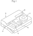
- a type-1 tape printing device 10 has a character input dial 12 on its upper face, and an operator can input characters by rotating it.
- the type-1 tape printing device 10 has a reverse image printing mode.
- the tape printing device also has a function key group 16 including, for example, a power switch 13, a print execution key 14 for setting various conditions with the tape printing device 10 and a liquid crystal display (abbreviated as LCD) 18.
- a function key group 16 including, for example, a power switch 13, a print execution key 14 for setting various conditions with the tape printing device 10 and a liquid crystal display (abbreviated as LCD) 18.
- LCD liquid crystal display
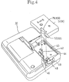
- a ribbon winding cam 22 and a tape sending roller cam 24 are driven by a motor (not shown) which drives the cams 22 and 24 in respective directions indicated by arrows in the figure.
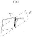
- thermal head 26 Inside the supporting member 20 is a thermal head 26 provided upright on the member.
- the thermal head 26 is so positioned that it is located inside of an aperture 75 of a tape cassette 51 when the tape cassette is installed onto the supporting member 20.
- thermal element 27 On the tip of the thermal head 26 is a thermal element 27 set across the width of the tape medium as illustrated in Fig.9.
- a reinforcement rib 28 stretching perpendicular to the direction the tape medium is sent.
- the reinforcement rib 28 is located in the groove 87 (shown in Fig. 5) of the tape cassette 51 when the tape cassette is installed to the supporting member 20.
- the type-2 tape printing device 30 which has a normal image printing mode, the mode not provided in the type-1 tape printing device 10, has a character input dial 32, a function key group 36 and a LCD 38.
- the type-2 tape printing device 30 has a printing mode selection key 35 in the function key group 36.
- the type-1 tape printing device 10 does not have a printing mode selection key 35 as found in the type-2 tape printing device 30, the type-1 tape printing device 10 has no optional mode other than the reverse image printing mode.
- the reinforcement rib 48 is molded into a different shape compared with the reinforcement rib 28 of the type-1 tape printing device 10.
- the reinforcement rib 48 of the type-2 tape printing device 30 has a notch 49 on the opposite side to the tape sending roller cam 44.
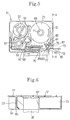
- the tape cassette 51 which can be installed to the supporting member 20 or 40 of the type-1 tape printing device 10 or the type-2 tape printing device 30 has a tape spool 55 to which tape print medium 53 consisting of a tape-like transparent film is wound. As shown in Fig. 5, the tape spool 55 is rotatably installed around a rotation shaft 57 provided upright from the main body of the tape cassette 51. Since the tape print medium consists of a transparent film, a reverse image printed on the print surface represents a normal image when it is viewed from the opposite side of the tape. The tape print medium is used as a print medium in the embodiment of the present invention.
- a ribbon supply spool 61 on which an ink ribbon 59 is wound.
- the ribbon supply spool 61 is rotatably installed on a rotation shaft 63 provided upright from the main body of the tape cassette 51.
- a winding up spool 65 which winds up the ink ribbon 59.
- the winding up spool 65 is rotatably supported in hole 67 provided on the main body of the tape cassette 51.
- engagement projections 68 Inside the bore of the winding up spool 65 are engagement projections 68, and the engagement projections engage with the ribbon winding cam 22 or 42 when the tape cassette is installed on the supporting member 20 or 40.
- a double-sided tape spool 69 On the right hand portion of the tape cassette 51 is a double-sided tape spool 69 rotatably installed around a rotation shaft 71 provided upright from the main body of the tape cassette 51.
- a double-sided adhesive tape 73 with a releasable sheet 72 stuck only on one side is wound up to the double-sided tape spool 69 with the releasable sheet 72 facing outward.
- an aperture 75 is provided in the center bottom portion of the tape cassette 51.
- the print medium 53 and the ink ribbon 59 are guided toward the aperture 75 with the print surface of the tape print medium and ink-coated surface of the ink ribbon 59 kept in confrontation.
- the tape print medium 53 and the ink ribbon 59 are welded with pressure by the thermal head 26 or 46 and a crimp release member 77. During this process the print surface of the tape print medium 53 faces the thermal head 26 or 46.
- a tape sending roller 79 On the right side of said aperture 75 is a tape sending roller 79 rotatably supported in hole 81 formed on the main body of the tape cassette 51. Engagement projections 82 are molded inside the bore of the tape sending roller 79.
- a rotation roller 83 supported by the crimp release member 77 is arranged at the location where the tape cassette 51 and the tape sending roller 79 are set in confrontation after a tape cassette 51 is installed to said supporting member 20 or 40.
- the print surface of the tape print medium 53 and the surface without a releasable sheet of the double-sided adhesive tape 73 are kept in confrontation and guided between the tape sending roller 79 and the rotation roller 83.
- the tape print medium 53 and the double-sided adhesive tape 73 are stuck to each other by the tape sending roller 79 and the rotation roller 83.
- reception mount 85 On the right of said tape sending roller 79, in other words, at the right side bottom of the tape cassette 51 is a reception mount 85, which a movable blade (not shown) is pressable against. Above the reception mount 85 is a groove 87 provided with its aperture facing the back of the tape cassette 51, into which the reinforcement rib 28 or 48 is inserted when tape cassette is installed into the supporting member 20 or- 40. The reception mount 85 is thus reinforced against the pressure of said movable blade by the reinforcement rib 28 or 48 inserted in the groove 87.
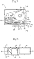
- the normal image tape cassette 91 shown in Fig. 7 is molded into the same appearance as the tape cassette 51.
- a tape spool 95 rotatably installed around a rotation shaft 97 extending from the main body of the cassette.
- the print tape medium 93 has an adhesive layer on an opposite side to the print surface and a releasable sheet 94 stuck on the adhesive layer.
- the tape print medium 93 is wound to the tape spool 95 with the releasable sheet 94 facing outward.
- the tape print medium 93 constitutes the single-sided adhesive tape used in this embodiment of the invention.
- a ribbon supply spool 101 to which an ink ribbon is wound, rotatably installed around a rotation shaft 103 extending from the main body of the normal image tape cassette 91.
- a winding up spool 105 On the right side of the ribbon supply spool 101 is a winding up spool 105 rotatably installed in hole 107 formed on the main body of the normal image tape cassette 91. Engagement projections 108 are molded inside the bore of the winding up spool 105.
- the ribbon winding up cam 42 is inserted into the winding up spool 105, and engages with the engagement projection 108 when the normal image tape cassette is installed on the supporting member of the type-2 tape printing device 30.
- an aperture 109 is provided in the center bottom of the tape cassette 91.
- the tape print medium 93 and the ink ribbon 99 are guided to the aperture 109 with the print surface of the tape print medium 93 and the ink-coated surface of ribbon 99 kept in confrontation.
- the tape print medium 93 and the ink ribbon 99 are welded with pressure by the thermal head 49 and the crimp release member 77 at the aperture 109. In this process, the print surface of the tape print medium 93 faces the thermal head 46.
- a tape sending roller 111 On the right side of the aperture 109 is a tape sending roller 111 rotatably installed in hole 113 formed on the main body of the normal image tape cassette 91. Engagement projections 115 are molded inside the bore of the tape sending roller 111.
- reception mount 117 On the right side of the tape sending roller 111, in other words, lower right portion of the normal image tape cassette is a reception mount 117 which a movable blade (not shown) is pressable against. As shown in Fig. 7 and 8, above the reception mount 117 is a groove 119. The reinforcement rib 48 is installed into the groove 119 thereby reinforcing the reception mount 117 against the pressure of said movable blade.
- a rib 121 is molded inside the groove 119.
- the rib abuts the upper end of the reinforcement rib 28 and prevents the normal image tape cassette 91 from being installed to the supporting member 20 of the tape printing device 10. Meanwhile, when the normal image tape cassette 91 is installed to the supporting member 40 of the type-2 tape printing device 30, the rib 121 corresponds to the notch 49 provided on the reinforcement rib 48, thus the normal image tape cassette 91 can be installed to the supporting member 40 of the tape printing device 30 without hindrance.
- the tape cassette 51 can be installed either to the supporting member 20 of the type-1 tape printing device 10 or to the support member 40 of the type-2 tape printing device 30. Since the type-1 tape printing device 10 operates only in the reverse image print mode, an instruction to print characters "ABC” causes the printing device 10 to drive the thermal head 26 and print a reversed image of characters "ABC” as shown in Fig. 10B on the print surface of the tape print medium 53. The surface of the tape print medium 53 carrying characters printed thereon is stuck to the surface without a releasable sheet of the double-sided adhesive tape 73, and the tape is discharged out of the tape cassette 51.
- the instruction to print characters "ABC” causes the type-2 tape printing device 30 to drive thermal head 46 and print a normal image of characters "ABC" on the surface of the tape print medium 53 as shown in Fig. 10A.
- the surface of the tape printing medium on which characters are printed is stuck to the surface without a releasable sheet 72 of the double-sided adhesive tape 73, and the tape is discharged from the tape cassette 51.
- the tape print medium made in this process represents a reverse image when viewed from the non-stick side of the tape print medium 53.
- the tape print medium represents a normal image when the tape is stuck to inside of a window pane and viewed from outside.
- the normal image tape cassette 91 has a rib 121 in its groove 119.
- the rib 121 abuts the reinforcement rib 28 provided in the supporting member 20 and prevents the tape cassette from being installed to the type-1 tape printing device 10.
- the prohibiting member eliminates the chance of the improper installation of the normal image tape cassette 91 to the type-1 tape printing device 10 without the normal image print mode, thereby saving print medium which otherwise would be wasted.
- the reinforcement rib 48 of the type-2 tape printing device 30 has a notch 49.
- the notch 49 allows the normal image tape cassette to be installed to the type-2 tape printing device 30. Giving the instruction to print characters "ABC" to the type-2 tape printing device in the normal image print mode causes the printing device to print a normal image on the print surface of the tape print medium 93 as shown in the Fig. 10A.
- the present embodiment of the invention provides a normal print mode tape cassette which prohibits improper installation of a tape cassette to a tape printing device without a normal image print mode.
Landscapes
- Printers Characterized By Their Purpose (AREA)
- Impression-Transfer Materials And Handling Thereof (AREA)
- Handling Of Continuous Sheets Of Paper (AREA)
- Dot-Matrix Printers And Others (AREA)
- Electronic Switches (AREA)
Claims (14)
- Bandkassette (91) zur Verwendung mit einer Banddruckvorrichtung, wobei die Kassette ein Kassettengehäuse zum Aufnehmen eines bandartigen Druckmediums (93), das nur mit einem Druckmodus, einem Umkehrbilddruckmodus oder einem Normalbilddruckmodus, kompatibel ist, aufweist,
dadurch gekennzeichnet,
daß die Kassette weiter Sperrmittel (121) aufweist, die dem Gehäuse zugeordnet sind, zum Sperren eines Eingriffs der Bandkassette mit einer Banddruckvorrichtung, die nicht zum Drucken in dem einen Druckmodus in der Lage ist, und zum Ermöglichen eines Eingriffs der Bandkassette in einer Banddruckvorrichtung, die zum Drucken in dem einen Druckmodus in der Lage ist. - Bandkassette nach Anspruch 1, bei der
das bandartige Druckmedium (93) eine Druckoberfläche auf einer Seite derselben, eine Klebeschicht auf einer dieser gegenüberliegenden Seite und eine Abziehschutzfolie, die an der Klebeschicht haftet, aufweist und das bandartige Druckmedium nur mit dem Normalbilddruckmodus kompatibel ist. - Bandkassette nach Anspruch 1 oder 2, bei der
das Sperrmittel eine nach außen vorstehende Rippe (121) ist. - Bandkassette nach einem der Ansprüche 1 bis 3, bei der
das Sperrmittel (121) ein integral geformtes Gebilde auf dem Gehäuse ist. - Bandkassette nach einem der vorhergehenden Ansprüche, bei der
das Kassettengehäuse in sich eine Nut (119) zum Empfangen eines Stützteils (48), das auf der Banddruckvorrichtung vorgesehen ist, aufweist und das Sperrmittel (121) ein Gebilde in der Nut ist. - Bandkassette nach einem der vorhergehenden Ansprüche, die weiter eine Schneideoberfläche (117) aufweist, gegen die Schneidemittel, die der Banddruckvorrichtung zugeordnet sind, im Gebrauch zum Schneiden angeordnet werden, um das bandartige Druckmedium (93), das sich nach einem Drucken von der Bandkassette erstreckt, abzutrennen, und das Sperrmittel (121) hinter der Schneideoberfläche zum Verstärken der Schneideoberfläche gegen die Wirkung des Schneidemittels positioniert ist.
- Banddruckvorrichtung (30) zum Drucken auf ein kompatibles bandartiges Druckmedium (93) in mindestens einem Druckmodus aus einem Normalbilddruckmodus und einem Umkehrbilddruckmodus, die aufweist:Druckmittel (46) zum Drucken auf ein kompatibles bandartiges Druckmedium (93), undHaltemittel (40) zum Empfangen einer Bandkassette (91), die ein kompatibles bandartiges Druckmedium (93), das zu bedrucken ist, enthält, wobei das Haltemittel Rippenmittel (48) zum Ineinadergreifen mit der Bandkassette (91), die das kompatible bandartige Druckmedium (93) enthält, aufweist, dadurch gekennzeichnet,
daß das Rippenmittel (48) in sich ein Gebilde (49) zum Empfangen eines dazu passenden Gebildes (121) auf der kompatiblen Bandkassette aufweist. - Banddruckvorrichtung nach Anspruch 7, bei der
die Druckvorrichtung (30) zum Drucken in sowohl dem Normalbilddruckmodus als auch dem Umkehrbilddruckmodus in der Lage ist. - Banddruckvorrichtung nach Anspruch 7, bei der
das Gebilde (49) der Banddruckvorrichtung eine Kerbe, die in dem Rippenmittel (48) ausgebildet ist, ist und die Kerbe (49) kompatibel mit einer Rippe (121) auf der kompatiblen Bandkassette ist. - Banddruckaufbau, der eine Kombination aus einer Kassette (91), wie sie in einem der Ansprüche 1 bis 6 beansprucht ist, und einer Banddruckvorrichtung (30), wie sie in einem der Ansprüche 7 bis 9 beansprucht ist, aufweist.
- Aufbau nach Anspruch 10, bei dem
die Kassette in der Druckvorrichtung aufgenommen wird und das Rippenmittel der Druckvorrichtung in einem zueinander passenden Eingriff mit dem Sperrmittel (121) der Kassette (91) ist. - Banddruckaufbau, der aufweist:eine Bandkassette (91), wie sie in einem der Ansprüche 1 bis 6 beansprucht ist, und eine Banddruckvorrichtung (30), die zum Drucken in mindestens einem Druckmodus in der Lage ist, wobei die VorrichtungDruckmittel (46) zum Drucken in mindestens dem einen Druckmodus auf das bandartige Druckmedium und Haltemittel (40) zum Empfangen der Bandkassette (91), die das zu bedruckende Druckmedium enthält, aufweist, und die in sich Rippenmittel (48) zum Ineinandergreifen mit dem Kassettengehäuse enthält, wobei das Rippenmittel (48) in sich ein Gebilde (49) zum Empfangen des Sperrmittels (121) der Bandkassette aufweist.
- Banddruckaufbau nach Anspruch 12, wenn dieser von Anspruch 5 abhängig ist, bei dem die Kassettengehäusenut (119) zum Empfangen des Rippenmittels (48) der Banddruckvorrichtung vorgesehen ist.
- Banddruckaufbau nach Anspruch 12 oder 13, bei dem
die Druckvorrichtung (30) zum Drucken in sowohl dem Normalbilddruckmodus als auch dem Umkehrbilddruckmodus in der Lage ist.
Applications Claiming Priority (2)
| Application Number | Priority Date | Filing Date | Title |
|---|---|---|---|
| JP22622/92 | 1992-02-07 | ||
| JP4022622A JPH05221064A (ja) | 1992-02-07 | 1992-02-07 | 正像印刷用テープカセット |
Publications (3)
| Publication Number | Publication Date |
|---|---|
| EP0555057A2 EP0555057A2 (de) | 1993-08-11 |
| EP0555057A3 EP0555057A3 (de) | 1994-02-02 |
| EP0555057B1 true EP0555057B1 (de) | 1997-05-07 |
Family
ID=12087933
Family Applications (1)
| Application Number | Title | Priority Date | Filing Date |
|---|---|---|---|
| EP93300764A Expired - Lifetime EP0555057B1 (de) | 1992-02-07 | 1993-02-03 | Kompatible Bandkassette und auf Band druckendes Gerät |
Country Status (4)
| Country | Link |
|---|---|
| US (1) | US5324123A (de) |
| EP (1) | EP0555057B1 (de) |
| JP (1) | JPH05221064A (de) |
| DE (1) | DE69310400T2 (de) |
Families Citing this family (8)
| Publication number | Priority date | Publication date | Assignee | Title |
|---|---|---|---|---|
| GB9212004D0 (en) * | 1992-06-05 | 1992-07-15 | Esselte Dymo Nv | Printing apparatus |
| US5816720A (en) * | 1994-03-15 | 1998-10-06 | Interbold | Printer mechanism for automated teller machine |
| US5657434A (en) * | 1994-10-05 | 1997-08-12 | Brother Kogyo Kabushiki Kaisha | Method and apparatus for inputting, displaying and printing images |
| USD379638S (en) * | 1995-11-10 | 1997-06-03 | Verbatim Corporation | Extended tape cartridge |
| DE59608999D1 (de) * | 1995-11-10 | 2002-05-08 | Esselte Nv | Satz von Bandkassetten und Druckgerät |
| JPH10291707A (ja) * | 1997-04-15 | 1998-11-04 | Brother Ind Ltd | ウエッブロール及びウエッブロール収納カセット |
| JP3843959B2 (ja) * | 2003-03-28 | 2006-11-08 | ブラザー工業株式会社 | テープ印字装置 |
| JP2006110814A (ja) * | 2004-10-13 | 2006-04-27 | Seiko Epson Corp | カートリッジ装着システムおよびこれに用いられる第2カートリッジ |
Family Cites Families (9)
| Publication number | Priority date | Publication date | Assignee | Title |
|---|---|---|---|---|
| US4511721A (en) * | 1982-03-03 | 1985-04-16 | Southern Research Institute | Intermediate for preparing antifungal 1,2-dihydropyrido[3,4-b]-pyrazines |
| JPS6147659U (ja) * | 1984-08-31 | 1986-03-31 | シチズン時計株式会社 | リボンカ−トリツジ |
| JPH0655539B2 (ja) * | 1986-01-27 | 1994-07-27 | 日本電気株式会社 | 印字装置の多色インクリボン切替機構 |
| JPH0630449Y2 (ja) * | 1986-09-08 | 1994-08-17 | ブラザー工業株式会社 | 印字装置 |
| US4927278A (en) * | 1987-12-29 | 1990-05-22 | Brother Kogyo Kabushiki Kaisha | Tape cassette and tape printer for use therewith |
| JPH0434048Y2 (de) * | 1988-10-17 | 1992-08-13 | ||
| JPH0719805Y2 (ja) * | 1989-02-08 | 1995-05-10 | ブラザー工業株式会社 | 印字装置 |
| DE4022696A1 (de) * | 1989-07-18 | 1991-01-31 | Canon Kk | Verfahren und vorrichtung zur ausbildung von aufzeichnungen mittels eines mehrfarben-farbbandes |
| JPH0368443A (ja) * | 1989-08-08 | 1991-03-25 | Babcock Hitachi Kk | 気―個系接触反応装置およびその充填層の焼損防止法 |
-
1992
- 1992-02-07 JP JP4022622A patent/JPH05221064A/ja active Pending
- 1992-11-24 US US07/980,721 patent/US5324123A/en not_active Expired - Fee Related
-
1993
- 1993-02-03 DE DE69310400T patent/DE69310400T2/de not_active Expired - Fee Related
- 1993-02-03 EP EP93300764A patent/EP0555057B1/de not_active Expired - Lifetime
Also Published As
| Publication number | Publication date |
|---|---|
| US5324123A (en) | 1994-06-28 |
| JPH05221064A (ja) | 1993-08-31 |
| EP0555057A3 (de) | 1994-02-02 |
| EP0555057A2 (de) | 1993-08-11 |
| DE69310400D1 (de) | 1997-06-12 |
| DE69310400T2 (de) | 1997-09-18 |
Similar Documents
| Publication | Publication Date | Title |
|---|---|---|
| EP1502757B1 (de) | Bandkassette | |
| US6149325A (en) | Tape printing device and tape cartridge used therein | |
| CA2108332A1 (en) | Tape cartridge and printing device | |
| US5492282A (en) | Refillable tape cassettes of varying thicknesses with unique spool mounting structures | |
| EP0555954B1 (de) | Bandkassette | |
| EP0555057B1 (de) | Kompatible Bandkassette und auf Band druckendes Gerät | |
| EP0607025A2 (de) | Druckvorrichtung mit Kassette | |
| EP0835812B1 (de) | Abziehvorrichtung für den Rand eines mit Trennpapier versehenen Blattes | |
| EP0551208B1 (de) | Druckvorrichtung und Bandkassetten unterschiedlicher Dicke | |
| JP2879636B2 (ja) | 印字シートカートリッジおよび印字機器 | |
| JP3041516B2 (ja) | 印字シートカートリッジ | |
| JP2811174B2 (ja) | 印字テープカートリッジ | |
| JP2893499B2 (ja) | テープカートリッジおよびテープライタ | |
| JP3129546B2 (ja) | インクリボンカートリッジおよび印字機器 | |
| JP3002817B2 (ja) | テープ印字装置 | |
| JP2916912B2 (ja) | 印字機器 | |
| JP3041518B2 (ja) | 印字装置 | |
| JP3472203B2 (ja) | テープ印字装置及びインクリボンカセット | |
| JP3041517B2 (ja) | 印字シートカートリッジ | |
| JP3041521B2 (ja) | 印字シートカートリッジ | |
| JP3002815B2 (ja) | 印字シートカートリッジ | |
| JP3091175B2 (ja) | テープ印字装置 | |
| JP3041519B2 (ja) | テープカートリッジ | |
| JP2995655B2 (ja) | 印字機器 | |
| JP2002113914A (ja) | テープ印刷装置 |
Legal Events
| Date | Code | Title | Description |
|---|---|---|---|
| PUAI | Public reference made under article 153(3) epc to a published international application that has entered the european phase |
Free format text: ORIGINAL CODE: 0009012 |
|
| AK | Designated contracting states |
Kind code of ref document: A2 Designated state(s): BE DE FR GB |
|
| PUAL | Search report despatched |
Free format text: ORIGINAL CODE: 0009013 |
|
| AK | Designated contracting states |
Kind code of ref document: A3 Designated state(s): BE DE FR GB |
|
| 17P | Request for examination filed |
Effective date: 19940415 |
|
| 17Q | First examination report despatched |
Effective date: 19950803 |
|
| GRAG | Despatch of communication of intention to grant |
Free format text: ORIGINAL CODE: EPIDOS AGRA |
|
| GRAH | Despatch of communication of intention to grant a patent |
Free format text: ORIGINAL CODE: EPIDOS IGRA |
|
| GRAH | Despatch of communication of intention to grant a patent |
Free format text: ORIGINAL CODE: EPIDOS IGRA |
|
| GRAA | (expected) grant |
Free format text: ORIGINAL CODE: 0009210 |
|
| AK | Designated contracting states |
Kind code of ref document: B1 Designated state(s): BE DE FR GB |
|
| PG25 | Lapsed in a contracting state [announced via postgrant information from national office to epo] |
Ref country code: BE Effective date: 19970507 |
|
| REF | Corresponds to: |
Ref document number: 69310400 Country of ref document: DE Date of ref document: 19970612 |
|
| ET | Fr: translation filed | ||
| PGFP | Annual fee paid to national office [announced via postgrant information from national office to epo] |
Ref country code: GB Payment date: 19980126 Year of fee payment: 6 |
|
| PGFP | Annual fee paid to national office [announced via postgrant information from national office to epo] |
Ref country code: DE Payment date: 19980206 Year of fee payment: 6 |
|
| PGFP | Annual fee paid to national office [announced via postgrant information from national office to epo] |
Ref country code: FR Payment date: 19980210 Year of fee payment: 6 |
|
| PLBE | No opposition filed within time limit |
Free format text: ORIGINAL CODE: 0009261 |
|
| STAA | Information on the status of an ep patent application or granted ep patent |
Free format text: STATUS: NO OPPOSITION FILED WITHIN TIME LIMIT |
|
| 26N | No opposition filed | ||
| PG25 | Lapsed in a contracting state [announced via postgrant information from national office to epo] |
Ref country code: GB Free format text: LAPSE BECAUSE OF NON-PAYMENT OF DUE FEES Effective date: 19990203 |
|
| GBPC | Gb: european patent ceased through non-payment of renewal fee |
Effective date: 19990203 |
|
| PG25 | Lapsed in a contracting state [announced via postgrant information from national office to epo] |
Ref country code: FR Free format text: LAPSE BECAUSE OF NON-PAYMENT OF DUE FEES Effective date: 19991029 |
|
| PG25 | Lapsed in a contracting state [announced via postgrant information from national office to epo] |
Ref country code: DE Free format text: LAPSE BECAUSE OF NON-PAYMENT OF DUE FEES Effective date: 19991201 |
|
| REG | Reference to a national code |
Ref country code: FR Ref legal event code: ST |