EP0552592A1 - Rotary vice for application on the rotary table of a transfer apparatus - Google Patents
Rotary vice for application on the rotary table of a transfer apparatus Download PDFInfo
- Publication number
- EP0552592A1 EP0552592A1 EP92830597A EP92830597A EP0552592A1 EP 0552592 A1 EP0552592 A1 EP 0552592A1 EP 92830597 A EP92830597 A EP 92830597A EP 92830597 A EP92830597 A EP 92830597A EP 0552592 A1 EP0552592 A1 EP 0552592A1
- Authority
- EP
- European Patent Office
- Prior art keywords
- vice
- shaft
- rotary
- locking ring
- workpiece
- Prior art date
- Legal status (The legal status is an assumption and is not a legal conclusion. Google has not performed a legal analysis and makes no representation as to the accuracy of the status listed.)
- Withdrawn
Links
Images


Classifications
-
- B—PERFORMING OPERATIONS; TRANSPORTING
- B23—MACHINE TOOLS; METAL-WORKING NOT OTHERWISE PROVIDED FOR
- B23Q—DETAILS, COMPONENTS, OR ACCESSORIES FOR MACHINE TOOLS, e.g. ARRANGEMENTS FOR COPYING OR CONTROLLING; MACHINE TOOLS IN GENERAL CHARACTERISED BY THE CONSTRUCTION OF PARTICULAR DETAILS OR COMPONENTS; COMBINATIONS OR ASSOCIATIONS OF METAL-WORKING MACHINES, NOT DIRECTED TO A PARTICULAR RESULT
- B23Q1/00—Members which are comprised in the general build-up of a form of machine, particularly relatively large fixed members
- B23Q1/25—Movable or adjustable work or tool supports
- B23Q1/26—Movable or adjustable work or tool supports characterised by constructional features relating to the co-operation of relatively movable members; Means for preventing relative movement of such members
- B23Q1/28—Means for securing sliding members in any desired position
- B23Q1/287—Means for securing sliding members in any desired position using a hydraulically controlled membrane acting directly upon a sliding member
-
- B—PERFORMING OPERATIONS; TRANSPORTING
- B23—MACHINE TOOLS; METAL-WORKING NOT OTHERWISE PROVIDED FOR
- B23Q—DETAILS, COMPONENTS, OR ACCESSORIES FOR MACHINE TOOLS, e.g. ARRANGEMENTS FOR COPYING OR CONTROLLING; MACHINE TOOLS IN GENERAL CHARACTERISED BY THE CONSTRUCTION OF PARTICULAR DETAILS OR COMPONENTS; COMBINATIONS OR ASSOCIATIONS OF METAL-WORKING MACHINES, NOT DIRECTED TO A PARTICULAR RESULT
- B23Q39/00—Metal-working machines incorporating a plurality of sub-assemblies, each capable of performing a metal-working operation
- B23Q39/04—Metal-working machines incorporating a plurality of sub-assemblies, each capable of performing a metal-working operation the sub-assemblies being arranged to operate simultaneously at different stations, e.g. with an annular work-table moved in steps
- B23Q39/042—Metal-working machines incorporating a plurality of sub-assemblies, each capable of performing a metal-working operation the sub-assemblies being arranged to operate simultaneously at different stations, e.g. with an annular work-table moved in steps with circular arrangement of the sub-assemblies
-
- Y—GENERAL TAGGING OF NEW TECHNOLOGICAL DEVELOPMENTS; GENERAL TAGGING OF CROSS-SECTIONAL TECHNOLOGIES SPANNING OVER SEVERAL SECTIONS OF THE IPC; TECHNICAL SUBJECTS COVERED BY FORMER USPC CROSS-REFERENCE ART COLLECTIONS [XRACs] AND DIGESTS
- Y10—TECHNICAL SUBJECTS COVERED BY FORMER USPC
- Y10T—TECHNICAL SUBJECTS COVERED BY FORMER US CLASSIFICATION
- Y10T29/00—Metal working
- Y10T29/51—Plural diverse manufacturing apparatus including means for metal shaping or assembling
- Y10T29/5124—Plural diverse manufacturing apparatus including means for metal shaping or assembling with means to feed work intermittently from one tool station to another
- Y10T29/5127—Blank turret
- Y10T29/5128—Rotary work - vertical axis
-
- Y—GENERAL TAGGING OF NEW TECHNOLOGICAL DEVELOPMENTS; GENERAL TAGGING OF CROSS-SECTIONAL TECHNOLOGIES SPANNING OVER SEVERAL SECTIONS OF THE IPC; TECHNICAL SUBJECTS COVERED BY FORMER USPC CROSS-REFERENCE ART COLLECTIONS [XRACs] AND DIGESTS
- Y10—TECHNICAL SUBJECTS COVERED BY FORMER USPC
- Y10T—TECHNICAL SUBJECTS COVERED BY FORMER US CLASSIFICATION
- Y10T29/00—Metal working
- Y10T29/51—Plural diverse manufacturing apparatus including means for metal shaping or assembling
- Y10T29/5124—Plural diverse manufacturing apparatus including means for metal shaping or assembling with means to feed work intermittently from one tool station to another
- Y10T29/5127—Blank turret
- Y10T29/5129—Rotary work - horizontal axis
Definitions
- the present invention relates to a rotary vice which can be specifically applied on the rotary table of a transfer machining apparatus.
- prior rotary-table transfer apparatus including for example a vertical table having a horizontal rotary axis, there subsists frequently the need of causing the workpieces to be turned, said workpieces being mounted on the apparatus table according to preset axes, so as to subsequently perform thereon the several desired machining operations.
- the aim of the present invention is to overcome the above mentioned drawbacks, by providing a rotary vice which can be specifically applied on a rotary table of a transfer machining apparatus, which allows a workpiece to be easily and quickly locked and unlocked by means which do not hinder the provided machining operations.
- a main object of the present invention is to provide such a rotary vice in which the hydraulic circuit for controlling the cylinder assembly for unlocking the angular divider of the rotary jaws of the vice is completely arranged inside the rotary vice.
- Another object of the present invention is to provide such a rotary vice which is very reliable and safe in operation.
- Yet another object of the present invention is to provide such a vice which can be easily made starting from easily available elements and materials and which, moreover, is very competitive from a mere economic standpoint.
- a rotary vice provided for application on a rotary table of a transfer machining apparatus, characterized in that said vice comprises a first and second opposite vice bodies, cooperating for holding therebetween a workpiece to be machined, said vice being supported on a rotary table of said apparatus, inside each said body there being rotatably supported a shaft in turn supporting a jaw element for holding the workpiece, a removable locking ring element being moreover provided for locking said shaft, hydraulic cylinder means being also provided for disengaging said locking ring element, gear means being connected to one of said shaft, on a side thereof, opposite to said jaw, said gear means being provided for connection with an outer divider assembly for rotating said shaft.
- the rotary vice construction specifically designed for application on the rotary table of a transfer machining apparatus, according to the present invention, which has been generally indicated at the reference number 1, comprises a first and second vice bodies, respectively 2 and 3, which are connected to the rotary table 4 of a transfer machining apparatus.
- Each body 2 and 3 rotatably supports, in its inside, a shaft 10 which, at one end thereof, projecting from the body 1, supports jaw elements which can be of any suitable types.
- the opposite bodies 2 and 3 practically provide a rotary vice which has aligned axes 10.
- a piston 15 which can be connected to a hydraulic circuit, which is tightly housed in a chamber 16, defined inside the body and, at its front axial end portion operating on pins 17 which, at the other end portion, engage with a block 18 which is keyed on the shaft 10 through the interposition of a sleeve 19 also keyed on the shaft 10.
- a pressure spring 21 which operates by pressure on the locking ring element 20, in order to lock the shaft with respect to the related body in which the shaft is arranged.
- an outer gear 30 which is adapted to be removably coupled with the gear 40 of an outer drive assembly, indicated at the reference number 41.
- the piston 15 will be caused to translate and, by overcoming the resilient biassing action provided by the cup springs 21, it will remove the axial compression on the locking ring 20, thereby the shaft will be free of rotating.
- the shaft can either rotate with respect to the body 2 or 3, or can be locked, and it can also be provided, at the end portion thereof or in its inside, with suitable fittings for connection with other devices, such as, for example clamp assemblies, drive assemblies for quickly engaging or disengaging the clamps, sensors, cams, transducers, and the like.
- the rotation of the shaft is applied from outside by means of a gear transmission and the shaft, which is supported by suitable bearings, as is rotated, affords the possibility of re-arranging a workpiece at well defined angular position, or causing the workpiece to be fed with an angular type of motion, or it is also adapted to cause said workpiece to turn.
- the locking is obtained by means of the above mentioned locking ring which is compressed by the pack springs 21.
- the shaft can be easily and quickly locked.
- the locking ring element in addition to angularly locking the shaft, will subject said shaft to an axial force, which will be discharged on the main thrust bearing, and will be added to the forces already operating on this bearing because of the workpiece locking effect provided by the vice.
- the shaft is unlocked by removing the axial pressure of the bush by means of the pins 17 which affect the block arranged at the pack springs.
- the front region is that where operates the expansion bush and where there are arranged the bearings for properly locating the shaft.
- the shaft can be located with a very great accuracy, both during its turning movements and during its indexing movements.
- the outer drive assembly 41 substantially comprises a device which provides four functions, that is an approaching, by means of a numeric control unit, which allows the mechanic drive to be arranged with a sufficient accuracy, with respect to the divider device, and causes the gear 30 to mesh with the gear wheel 41, in a ripetitive way and with a very good accuracy, both with respect to the gear inter-axes and with respect to the load acting thereon.
- the centering operation is performed by a suitable means allowing the mechanical drive to be located with a sufficient precision with respect to divider device.
- the rotation of the clamps is performed by a numeric control unit, having a transducer which is rigidly connected to the last wheel of the gear wheel chain.
- the wheel which directly engages with the outer gear 30, connected to the rotary clamps, as stated, provides the possibility of obtaining several movements, such as an angular feeding movement, an indexing movement, to an infinite series of angular positions, as well as of holding the workpiece locked in the vice.
- the used materials, as well as the contingent size and shape can be any, according to requirements.
Abstract
Description
- The present invention relates to a rotary vice which can be specifically applied on the rotary table of a transfer machining apparatus.
- As is known, prior rotary-table transfer apparatus, including for example a vertical table having a horizontal rotary axis, there subsists frequently the need of causing the workpieces to be turned, said workpieces being mounted on the apparatus table according to preset axes, so as to subsequently perform thereon the several desired machining operations.
- At present the adopted approaches have been found to be rather unsatisfactory and involve great constructional problems, mainly with respect to the arrangement of the means for removably preventing the workpiece from being rotated, and the means provided for rotatably driving said workpiece, according to preset angles and procedures.
- Accordingly, the aim of the present invention is to overcome the above mentioned drawbacks, by providing a rotary vice which can be specifically applied on a rotary table of a transfer machining apparatus, which allows a workpiece to be easily and quickly locked and unlocked by means which do not hinder the provided machining operations.
- Within the above mentioned aim, a main object of the present invention is to provide such a rotary vice in which the hydraulic circuit for controlling the cylinder assembly for unlocking the angular divider of the rotary jaws of the vice is completely arranged inside the rotary vice.
- Another object of the present invention is to provide such a rotary vice which is very reliable and safe in operation.
- Yet another object of the present invention is to provide such a vice which can be easily made starting from easily available elements and materials and which, moreover, is very competitive from a mere economic standpoint.
- According to one aspect of the present invention, the above mentioned aim and objects, as well as yet other objects, which will become more apparent hereinafter, are achieved by a rotary vice, provided for application on a rotary table of a transfer machining apparatus, characterized in that said vice comprises a first and second opposite vice bodies, cooperating for holding therebetween a workpiece to be machined, said vice being supported on a rotary table of said apparatus, inside each said body there being rotatably supported a shaft in turn supporting a jaw element for holding the workpiece, a removable locking ring element being moreover provided for locking said shaft, hydraulic cylinder means being also provided for disengaging said locking ring element, gear means being connected to one of said shaft, on a side thereof, opposite to said jaw, said gear means being provided for connection with an outer divider assembly for rotating said shaft.
- Further characteristics and advantages of the invention will become more apparent from the following detailed disclosure of a preferred, though not exclusive, embodiment thereof, which is illustrated, by way of an indicative, but not limitative example, in the figures of the accompanying drawings, where:
- Figure 1 is a schematic front view illustrating the rotary table on which there is applied the rotary vice according to the present invention;
- Figure 2 is a schematic elevation view illustrating the transfer apparatus with the related rotary table;
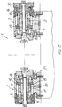
and - Figure 3 is a schematic cross-sectional view illustrating the rotary vice.
- With reference to the number references of the figures of the accompanying drawings, the rotary vice construction, specifically designed for application on the rotary table of a transfer machining apparatus, according to the present invention, which has been generally indicated at the reference number 1, comprises a first and second vice bodies, respectively 2 and 3, which are connected to the rotary table 4 of a transfer machining apparatus.
- Each
body shaft 10 which, at one end thereof, projecting from the body 1, supports jaw elements which can be of any suitable types. - The
opposite bodies axes 10. - If with the word "front portion" there are called the mutually opposite portions of the
bodies piston 15, which can be connected to a hydraulic circuit, which is tightly housed in achamber 16, defined inside the body and, at its front axial end portion operating onpins 17 which, at the other end portion, engage with ablock 18 which is keyed on theshaft 10 through the interposition of asleeve 19 also keyed on theshaft 10. - On the
block 18 operates apressure spring 21 which operates by pressure on thelocking ring element 20, in order to lock the shaft with respect to the related body in which the shaft is arranged. - On one of the
shafts 10 and, making specific reference to the drawings, on theshaft 10 of thebody 3, there is keyed anouter gear 30, which is adapted to be removably coupled with thegear 40 of an outer drive assembly, indicated at thereference number 41. - With the disclosed arrangement, as the
chamber 16 is pressurized, thepiston 15 will be caused to translate and, by overcoming the resilient biassing action provided by thecup springs 21, it will remove the axial compression on thelocking ring 20, thereby the shaft will be free of rotating. - Owing to the connect.ion with the drive assembly, it will be possible to cause said shaft to rotate as desired.
- In order to lock the shaft, it is sufficient to remove the pressure from the
chamber 16, so as to cause thecup springs 21 to axially press on the locking ring, so as to hold said shaft in a set locked position. - It should be apparent that the shaft can either rotate with respect to the
body - The rotation of the shaft is applied from outside by means of a gear transmission and the shaft, which is supported by suitable bearings, as is rotated, affords the possibility of re-arranging a workpiece at well defined angular position, or causing the workpiece to be fed with an angular type of motion, or it is also adapted to cause said workpiece to turn.
- The locking is obtained by means of the above mentioned locking ring which is compressed by the
pack springs 21. - Thus, by the disclosed ring element, the shaft can be easily and quickly locked.
- The locking ring element, in addition to angularly locking the shaft, will subject said shaft to an axial force, which will be discharged on the main thrust bearing, and will be added to the forces already operating on this bearing because of the workpiece locking effect provided by the vice.
- As stated, the shaft is unlocked by removing the axial pressure of the bush by means of the
pins 17 which affect the block arranged at the pack springs. - This provision affords the possibility of arranging hydraulic cylinders at the rear of the shaft and outside of the framework of the apparatus.
- The front region is that where operates the expansion bush and where there are arranged the bearings for properly locating the shaft.
- Since the unlocking cylinder is not arranged at the front of the apparatus, the shaft can be located with a very great accuracy, both during its turning movements and during its indexing movements.
- The
outer drive assembly 41 substantially comprises a device which provides four functions, that is an approaching, by means of a numeric control unit, which allows the mechanic drive to be arranged with a sufficient accuracy, with respect to the divider device, and causes thegear 30 to mesh with thegear wheel 41, in a ripetitive way and with a very good accuracy, both with respect to the gear inter-axes and with respect to the load acting thereon. - Moreover, it is possible to easily wash the gear teeth and the locking and reference surface, by means of suitable nozzles.
- The centering operation is performed by a suitable means allowing the mechanical drive to be located with a sufficient precision with respect to divider device.
- Moreover, the rotation of the clamps is performed by a numeric control unit, having a transducer which is rigidly connected to the last wheel of the gear wheel chain.
- The wheel, which directly engages with the
outer gear 30, connected to the rotary clamps, as stated, provides the possibility of obtaining several movements, such as an angular feeding movement, an indexing movement, to an infinite series of angular positions, as well as of holding the workpiece locked in the vice. - The invention as disclosed is suceptible to several modifications and variations all of which will come within the scope of the inventive idea.
- Moreover,, all of the details can be replaced by other technically equivalent elements.
- In practicing the invention, the used materials, as well as the contingent size and shape, can be any, according to requirements.
Claims (5)
- A rotary vice, provided for application on a rotary table of a transfer machining apparatus,
characterized in that said vice comprises a first and second opposite vice bodies, cooperating for holding therebetween a workpiece to be machined, said vice being supported on a rotary table of said apparatus, inside each said body there being rotatably supported a shaft in turn supporting a jaw element for holding the workpiece, a removable locking ring element being moreover provided for locking said shaft, hydraulic cylinder means being provided for disengaging said locking ring element, gear means being connected to one of said shaft, on a side thereof, opposite to said jaw, said gear means being provided for connection with an outer divider assembly for rotating said shaft. - A rotary vice, according to Claim 1,
characterized in that the hydraulic cylinder is housed in said body on a side thereof opposite to the jaw forming end portions. - A rotary vice, according to Claim 2,
characterized in that said hydraulic cylinder operates, at a front end portion thereof, on pin means engaging with a block element which is rotatively rigid with said shaft, on said block operating pressure springs for axially pressing said locking ring. - A rotary vice, according to Claim 3,
characterized in that said locking ring operates between the inside of the body and the outer surface of a sleeve which is rigidly connected to said shaft. - A rotary vice, according to Claim 1,
characterized in that the drive assembly of said shaft is so arranged as to provide an approaching displacement for coupling with the outer gear, a washing of the gear teeth, a centering operation, and being moreover adapted to provide a rotary drive according to a plurality of preset angular positions, and a continuous rotary movement.
Applications Claiming Priority (2)
| Application Number | Priority Date | Filing Date | Title |
|---|---|---|---|
| ITMI913230A IT1252152B (en) | 1991-12-03 | 1991-12-03 | REVOLVING VICE STRUCTURE, APPLICABLE IN PARTICULAR TO THE ROTARY TABLE OF A TRANSFER MACHINE |
| ITMI913230 | 1991-12-03 |
Publications (1)
| Publication Number | Publication Date |
|---|---|
| EP0552592A1 true EP0552592A1 (en) | 1993-07-28 |
Family
ID=11361239
Family Applications (1)
| Application Number | Title | Priority Date | Filing Date |
|---|---|---|---|
| EP92830597A Withdrawn EP0552592A1 (en) | 1991-12-03 | 1992-10-30 | Rotary vice for application on the rotary table of a transfer apparatus |
Country Status (3)
| Country | Link |
|---|---|
| US (1) | US5261148A (en) |
| EP (1) | EP0552592A1 (en) |
| IT (1) | IT1252152B (en) |
Cited By (3)
| Publication number | Priority date | Publication date | Assignee | Title |
|---|---|---|---|---|
| US5832590A (en) * | 1995-08-08 | 1998-11-10 | Wuerthner; Holger | System for machining workpieces |
| CN103495868A (en) * | 2013-09-30 | 2014-01-08 | 无锡众望四维科技有限公司 | Lock cylinder automatic machining device |
| CN103495867A (en) * | 2013-09-30 | 2014-01-08 | 无锡众望四维科技有限公司 | Lock body automatic machining device |
Families Citing this family (5)
| Publication number | Priority date | Publication date | Assignee | Title |
|---|---|---|---|---|
| US5421072A (en) * | 1993-10-26 | 1995-06-06 | Kurt Manufacturing Company, Inc. | Machining carousel |
| DE19533320C2 (en) * | 1995-09-08 | 1999-01-28 | Ottobeurer Facondreherei Alois | Rotary transfer machine |
| ITMI20012072A1 (en) * | 2001-10-05 | 2003-04-05 | Porta S P A | PERFECTED DEVICE FOR THE CONTROL OF THE LOCKING AND RELEASING MOVEMENT OF A ROTATING DISC WITH TOOTHED CROWN SYSTEM AND PROVIDED MACHINE |
| US7331093B2 (en) * | 2004-04-08 | 2008-02-19 | Dm2 Di Duina Gianfranco S.R.L. | Pieces hold-unit for workstations, transfer machines and like |
| US8028976B2 (en) * | 2007-10-15 | 2011-10-04 | Ocenco, Inc. | Machining fixture with self-contained hydraulics |
Citations (5)
| Publication number | Priority date | Publication date | Assignee | Title |
|---|---|---|---|---|
| US3153276A (en) * | 1961-08-24 | 1964-10-20 | Pipe Machinery Company | Multi-station machine including workholding and positioning apparatus |
| US3244028A (en) * | 1964-07-14 | 1966-04-05 | Cincinnati Milling Machine Co | Spindle clamping mechanism |
| CH461219A (en) * | 1967-08-05 | 1968-08-15 | Posalux Sa | Rotary table transfer machine |
| US3552240A (en) * | 1967-07-21 | 1971-01-05 | Werkzeugmaschinenfabrik Gildom | Work support for multi-station machine tools |
| AT372900B (en) * | 1980-04-23 | 1983-11-25 | Massak Franz Dipl Ing | DEVICE FOR THE MACHINE MANUFACTURING OF ROTATIONALLY SYMMETRIC FURNITURE KNOBS |
Family Cites Families (8)
| Publication number | Priority date | Publication date | Assignee | Title |
|---|---|---|---|---|
| US2876527A (en) * | 1956-06-22 | 1959-03-10 | Alfred H Schutte | Arresting device for the work spindles of multiple-spindle automatic lathes |
| DK99402C (en) * | 1961-12-04 | 1964-08-03 | F G M & Co Ved Per Gelbjerg Ha | Machine for placing a preferably membranous coating on the inside of capsules and similar cup-shaped articles. |
| SU539739A1 (en) * | 1975-06-02 | 1976-12-25 | Днепропетровский завод шахтной автоматики | Combined Metalworking Machine |
| US4351096A (en) * | 1980-08-28 | 1982-09-28 | White Consolidated Industries, Inc. | Multiple spindle rotary indexing machine tool |
| US4798276A (en) * | 1983-01-17 | 1989-01-17 | The Firestone Tire & Rubber Company | Shaping turret |
| JPS61192453A (en) * | 1985-02-19 | 1986-08-27 | Disco Abrasive Sys Ltd | Continuous machining device |
| EP0277713B1 (en) * | 1987-01-29 | 1991-08-28 | A.E. Bishop & Associates Pty. Limited | Indexing and transporting mechanism |
| MY106219A (en) * | 1989-02-22 | 1995-04-29 | Mitsubishi Mat Coporation | Apparatus for rotating top ends of cans |
-
1991
- 1991-12-03 IT ITMI913230A patent/IT1252152B/en active IP Right Grant
-
1992
- 1992-10-30 EP EP92830597A patent/EP0552592A1/en not_active Withdrawn
- 1992-12-01 US US07/983,657 patent/US5261148A/en not_active Expired - Fee Related
Patent Citations (5)
| Publication number | Priority date | Publication date | Assignee | Title |
|---|---|---|---|---|
| US3153276A (en) * | 1961-08-24 | 1964-10-20 | Pipe Machinery Company | Multi-station machine including workholding and positioning apparatus |
| US3244028A (en) * | 1964-07-14 | 1966-04-05 | Cincinnati Milling Machine Co | Spindle clamping mechanism |
| US3552240A (en) * | 1967-07-21 | 1971-01-05 | Werkzeugmaschinenfabrik Gildom | Work support for multi-station machine tools |
| CH461219A (en) * | 1967-08-05 | 1968-08-15 | Posalux Sa | Rotary table transfer machine |
| AT372900B (en) * | 1980-04-23 | 1983-11-25 | Massak Franz Dipl Ing | DEVICE FOR THE MACHINE MANUFACTURING OF ROTATIONALLY SYMMETRIC FURNITURE KNOBS |
Cited By (4)
| Publication number | Priority date | Publication date | Assignee | Title |
|---|---|---|---|---|
| US5832590A (en) * | 1995-08-08 | 1998-11-10 | Wuerthner; Holger | System for machining workpieces |
| CN103495868A (en) * | 2013-09-30 | 2014-01-08 | 无锡众望四维科技有限公司 | Lock cylinder automatic machining device |
| CN103495867A (en) * | 2013-09-30 | 2014-01-08 | 无锡众望四维科技有限公司 | Lock body automatic machining device |
| CN103495868B (en) * | 2013-09-30 | 2015-09-16 | 无锡众望四维科技有限公司 | A kind of lock core automatic machining device |
Also Published As
| Publication number | Publication date |
|---|---|
| US5261148A (en) | 1993-11-16 |
| ITMI913230A0 (en) | 1991-12-03 |
| ITMI913230A1 (en) | 1993-06-03 |
| IT1252152B (en) | 1995-06-05 |
Similar Documents
| Publication | Publication Date | Title |
|---|---|---|
| US3483796A (en) | Angularly adjustable headstock attachment for use on machine tools | |
| US6629345B2 (en) | Chucking device | |
| US4657453A (en) | Milling device with universal gear and automatic indexation | |
| US5261148A (en) | Rotary vice for rotary table | |
| US4411440A (en) | Swinging chuck for turning machines | |
| US4437328A (en) | Crankshaft glaze or smooth rolling machine | |
| US4270375A (en) | Forming machine including rotary drive mechanism | |
| EP1083026A2 (en) | Operating unit with an automatic tool changing device and transfer tool machine including the same | |
| US3825387A (en) | Quick-change die and roller assembly | |
| US3790181A (en) | Swivel chuck for machining workpieces with a plurality of axes crossing each other | |
| US4026191A (en) | Machine tool | |
| JP2916165B2 (en) | Spindle device with phase indexing mechanism | |
| US2874595A (en) | Power turret indexing | |
| US4528876A (en) | Universal single spindle pin crankshaft lathe | |
| JPS62292304A (en) | Chuck with two opposite clamping pawl | |
| EP0900629B1 (en) | Apparatus for crankpin phase indexing | |
| JPH0420732B2 (en) | ||
| US7143665B2 (en) | Mechanical-hydraulic control device for controlling the locking and unlocking movements of rotary disk in a rotary disc table workpiece processing apparatus | |
| JPS62224541A (en) | Angle head | |
| HU177660B (en) | Punch bench for forming pipe ingots and method for working the rollers belonging to the punch bench | |
| EP0978335A1 (en) | Rotator for a machine for machining metal sheets | |
| WO1991003335A1 (en) | Turret punch press | |
| JPH05245574A (en) | Forging machine | |
| US4468893A (en) | Machine for machining and in particular grinding cylindrical surfaces | |
| JPH0525795Y2 (en) |
Legal Events
| Date | Code | Title | Description |
|---|---|---|---|
| PUAI | Public reference made under article 153(3) epc to a published international application that has entered the european phase |
Free format text: ORIGINAL CODE: 0009012 |
|
| AK | Designated contracting states |
Kind code of ref document: A1 Designated state(s): CH DE ES FR GB LI |
|
| 17P | Request for examination filed |
Effective date: 19931123 |
|
| 17Q | First examination report despatched |
Effective date: 19940919 |
|
| GRAG | Despatch of communication of intention to grant |
Free format text: ORIGINAL CODE: EPIDOS AGRA |
|
| GRAH | Despatch of communication of intention to grant a patent |
Free format text: ORIGINAL CODE: EPIDOS IGRA |
|
| GRAH | Despatch of communication of intention to grant a patent |
Free format text: ORIGINAL CODE: EPIDOS IGRA |
|
| STAA | Information on the status of an ep patent application or granted ep patent |
Free format text: STATUS: THE APPLICATION IS DEEMED TO BE WITHDRAWN |
|
| 18D | Application deemed to be withdrawn |
Effective date: 19970403 |