EP0900629B1 - Apparatus for crankpin phase indexing - Google Patents
Apparatus for crankpin phase indexing Download PDFInfo
- Publication number
- EP0900629B1 EP0900629B1 EP96937554A EP96937554A EP0900629B1 EP 0900629 B1 EP0900629 B1 EP 0900629B1 EP 96937554 A EP96937554 A EP 96937554A EP 96937554 A EP96937554 A EP 96937554A EP 0900629 B1 EP0900629 B1 EP 0900629B1
- Authority
- EP
- European Patent Office
- Prior art keywords
- shaft
- phase indexing
- phasing
- coupling
- main spindle
- Prior art date
- Legal status (The legal status is an assumption and is not a legal conclusion. Google has not performed a legal analysis and makes no representation as to the accuracy of the status listed.)
- Expired - Lifetime
Links
Images


Classifications
-
- B—PERFORMING OPERATIONS; TRANSPORTING
- B24—GRINDING; POLISHING
- B24B—MACHINES, DEVICES, OR PROCESSES FOR GRINDING OR POLISHING; DRESSING OR CONDITIONING OF ABRADING SURFACES; FEEDING OF GRINDING, POLISHING, OR LAPPING AGENTS
- B24B5/00—Machines or devices designed for grinding surfaces of revolution on work, including those which also grind adjacent plane surfaces; Accessories therefor
- B24B5/36—Single-purpose machines or devices
- B24B5/42—Single-purpose machines or devices for grinding crankshafts or crankpins
-
- B—PERFORMING OPERATIONS; TRANSPORTING
- B23—MACHINE TOOLS; METAL-WORKING NOT OTHERWISE PROVIDED FOR
- B23Q—DETAILS, COMPONENTS, OR ACCESSORIES FOR MACHINE TOOLS, e.g. ARRANGEMENTS FOR COPYING OR CONTROLLING; MACHINE TOOLS IN GENERAL CHARACTERISED BY THE CONSTRUCTION OF PARTICULAR DETAILS OR COMPONENTS; COMBINATIONS OR ASSOCIATIONS OF METAL-WORKING MACHINES, NOT DIRECTED TO A PARTICULAR RESULT
- B23Q16/00—Equipment for precise positioning of tool or work into particular locations not otherwise provided for
- B23Q16/02—Indexing equipment
-
- Y—GENERAL TAGGING OF NEW TECHNOLOGICAL DEVELOPMENTS; GENERAL TAGGING OF CROSS-SECTIONAL TECHNOLOGIES SPANNING OVER SEVERAL SECTIONS OF THE IPC; TECHNICAL SUBJECTS COVERED BY FORMER USPC CROSS-REFERENCE ART COLLECTIONS [XRACs] AND DIGESTS
- Y10—TECHNICAL SUBJECTS COVERED BY FORMER USPC
- Y10T—TECHNICAL SUBJECTS COVERED BY FORMER US CLASSIFICATION
- Y10T409/00—Gear cutting, milling, or planing
- Y10T409/30—Milling
- Y10T409/30868—Work support
- Y10T409/308792—Indexable
-
- Y—GENERAL TAGGING OF NEW TECHNOLOGICAL DEVELOPMENTS; GENERAL TAGGING OF CROSS-SECTIONAL TECHNOLOGIES SPANNING OVER SEVERAL SECTIONS OF THE IPC; TECHNICAL SUBJECTS COVERED BY FORMER USPC CROSS-REFERENCE ART COLLECTIONS [XRACs] AND DIGESTS
- Y10—TECHNICAL SUBJECTS COVERED BY FORMER USPC
- Y10T—TECHNICAL SUBJECTS COVERED BY FORMER US CLASSIFICATION
- Y10T74/00—Machine element or mechanism
- Y10T74/14—Rotary member or shaft indexing, e.g., tool or work turret
-
- Y—GENERAL TAGGING OF NEW TECHNOLOGICAL DEVELOPMENTS; GENERAL TAGGING OF CROSS-SECTIONAL TECHNOLOGIES SPANNING OVER SEVERAL SECTIONS OF THE IPC; TECHNICAL SUBJECTS COVERED BY FORMER USPC CROSS-REFERENCE ART COLLECTIONS [XRACs] AND DIGESTS
- Y10—TECHNICAL SUBJECTS COVERED BY FORMER USPC
- Y10T—TECHNICAL SUBJECTS COVERED BY FORMER US CLASSIFICATION
- Y10T82/00—Turning
- Y10T82/19—Lathe for crank or crank pin
- Y10T82/195—Lathe for crank or crank pin having work oscillator
- Y10T82/198—Lathe for crank or crank pin having work oscillator having work driver
Definitions
- the present invention relates to a crank pin phase indexing apparatus which is suitably embodied in crank pin grinding machines and the like.
- crank pin phase indexing apparatus there is known, for example, one having a constitution as disclosed in Japanese Unexamined Patent Publication No. Hei 3-19757.
- a chuck body is attached to the nose of each main spindle, and the chuck supports a phasing rotary shaft rotatable about an axis offset from the axis of the main spindle.
- a phase indexing shaft is supported in the main spindle along the center thereof to rotate relative to the main spindle on the same axis, and the distal end of the phase indexing shaft is connected to the phasing rotary shaft via a first coupling.
- a second coupling is located between the main spindle and the phase indexing shaft and releasably connects them.
- a differential gear mechanism is located between a drive motor and the main spindle and phase indexing shaft, and the main spindle and the phase indexing shaft are rotated, with the rotation of the drive motor, integrally or relative to each other via the differential gear mechanism. Further, a braking mechanism is connectable either to the main spindle or the phase indexing shaft.
- Indexing of a work crankshaft with respect to the axis of the main spindle is carried out after the second coupling is disengaged from the main spindle and after the main spindle is engaged with the braking mechanism. Since the main spindle is locked against rotation in this state, if the drive motor is driven, the phase indexing shaft is rotated relative to the main spindle via the differential gear mechanism. This rotation of the phase indexing shaft is transmitted to the phasing rotary shaft to achieve indexing of the workpiece supported by the chuck body at a predetermined phase with respect to the center of the workpiece.
- the second coupling is engaged with the main spindle and the braking mechanism is disengaged from the main spindle. Since the main spindle and the phase indexing shaft are connected to each other integrally in this state, the main spindle and the phase indexing shaft are rotated integrally via the differential gear mechanism when the drive motor is driven. Thus, the workpiece supported by the chuck bodies is rotated on the axis of the main spindle with a predetermined indexed phase. The workpiece chucked by the chuck body is rotated and machined.
- crank pin phase indexing apparatus a differential gear mechanism is located between the drive motor and the main spindle and phase indexing shaft, and the main spindle and the phase indexing shaft are rotated via this differential gear mechanism integrally or relative to each other for machining or indexing. Accordingly, a differential gear mechanism having a multiplicity of gears must be incorporated into the apparatus, which complicates the apparatus, degrades the working environment with gear beating noise and lowers the accuracy of the apparatus due to abrasion of the gears.
- US-A-2297926 discloses a crank pin phase indexing apparatus having a pair of toothed coupling plates.
- crank pin phase indexing apparatus as set out in claim 1.
- the invention provides a crank pin phase indexing apparatus that may have a simple constitution, a small size as a whole and can accurately index workpieces at predetermined phases.
- the invention may also prevent degradation of the working environment by gear beating noises. Further, the present invention may ensure clamping of workpieces and carry out accurate and smooth phase indexing of workpieces.
- the main spindle is rotated, the coupling is engaged and the locking means is deactuated. Since the chuck body and the phasing rotary shaft are connected integrally to each other in this state, the chuck body and the phasing rotary shaft are rotated integrally when the main spindle is rotated by the drive motor. Thus, the crankshaft, which is supported by the chuck body, is rotated on the axis of the main spindle while it maintains a predetermined indexed phase.
- the coupling can be a Curvic coupling having a pair of coupling plates, which can be moved closer to and farther from each other. Opposing faces of these coupling plates have teeth that can be meshed with their counterparts when the coupling plates are moved close to each other.
- a Curvic coupling having teeth and tooth spaces, which are brought together, constitutes the coupling between the phasing rotary shaft and the chuck in the present invention
- connection of the phasing rotary shaft with the chuck is secure.
- the Curvic coupling is designed such that the teeth thereof each have a trapezoidal cross section and that the tooth spaces each have a triangular or trapezoidal cross section, the accuracy of meshing between the teeth and tooth spaces is improved.
- the Curvic coupling is located between the phasing rotary shaft and the front end of the chuck, the rotation of the main spindle is transmitted directly to the chuck during machining, which contributes to high-accuracy machining.
- a bed 17 has on its upper surface a slide base 18 carrying a pair of saddles 19 and 20.
- One saddle 19 is fixed, and the other saddle 20 is slidable crosswise on the slide base 18.
- a first chuck body 25 is attached to the nose of the main spindle 22 in the drive side head 21, and a second chuck body 26 is attached to the nose of the main spindle 24 in the driven side head 23 to oppose the first chuck body 25.
- a work'crankshaft 27 has journals 271 and 272 at both end portions and a plurality of crank pins between the journals 271 and 272.
- the journals 271 and 272 are aligned on the same axis, and the crank pins 273 are arranged around the axis of the journals 271 and 272 at regular phase intervals.
- the crankshaft 27 is chucked between the chuck bodies 25 and 26 at both end journals 271 and 272.
- the space between the drive head 21 and the driven head 23 is adjusted by moving the saddle 20, depending on the length of the crankshaft 27.
- a first drive motor 30 is provided in the drive side head 21, and the main spindle 22 is rotated via a coupling 31 and a plurality of gears 32, 33, 34 and 35 by the rotation of the first drive motor 30.
- An encoder 36 is housed in the drive motor 30 and detects the rotational position of the main spindle 22 and synchronism of the main spindle 22 with respect to the main spindle 24.
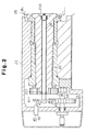
- a phase indexing shaft 39 forms part of the locking means, is supported via a pair of bearings 210 and 211 in the main spindle 22 to share the axis of the bearings 210, 211 to rotate relative to the main spindle 22, and a locking mechanism 40, also forming part of the locking means, is attached to the rear end of the shaft 39.
- This locking mechanism 40 is provided with a locking disc 41 fixed to the rear end portion of the phase indexing shaft 39, a locking pin 42 which is engageable with a plurality of engaging holes 411, and a locking cylinder 43 for engaging and disengaging the locking pin 42 with and from the locking holes 411.
- the phase indexing shaft 39 is non-rotatably locked.
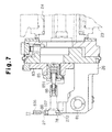
- the first chuck body 25 is made of a light-weight metallic material such as high-tension aluminum and has a clamping device 47 at its front end.
- this clamping device 47 is equipped with a fixed clamp member 48 fixed on the first chuck 25, a pivotal arm 49 pivotally attached to the first chuck 25 with a pivot 90, a movable clamp member 50 attached to the distal end portion of the pivotal arm 49, a clamping cylinder 51 for pivoting the pivotal arm 49, and a pivot turning device 98.
- the movable clamp member 50 is attached to the distal end portion of the pivotal arm 49 such that the clamp member 50 can swivel about a shaft 106.
- the movable clamp member 50 is forked to have two fingers, and a roller 107 is supported at the distal end portion of each finger to roll freely.
- the pivot 90 is supported at a medium-diameter portion 902 thereof via a bearing in a pivot supporting hole 211 defined in the chuck 21, and a large-diameter portion 901 of the pivot 90 rotatably supports the pivotal arm 49.
- the large-diameter portion 901 of the pivot 90 is offset by the distance ⁇ relative to the medium-diameter portion 902.
- the pivot 90 is turned via a gear 101 attached to a motor 100 of the pivot turning device 98 and a gear 102 attached to a small-diameter portion 903 of the pivot 90.
- the fixed clamp member 48 has an arcuate journal receiving face 108 which is hardened and is embedded with a plurality of chips 109 made of a hard metal.
- the chips 109 also constitute the receiving face 108.
- a movable piece 105 is located in the first chuck body 25 to move in a radial direction with respect to the axis of the main spindle 22.
- a phasing rotary shaft 53 is supported rotatably by the movable piece 105 via a pair of bearings 54 to be able to move in the radial direction closer to and farther from the axis of the main spindle 22 as the movable piece 105 moves.
- a Schmidt coupling (trade name) 55 is located between the phasing rotary shaft 53 and the phase indexing shaft 39 so that the phasing rotary shaft 53 can be aligned with the journal 271 of the crankshaft 27, which is clamped by the clamping device 47.
- the phasing rotary shaft 53 and the phase indexing shaft 39 are connected to each other via this Schmidt coupling 55, and the phasing rotary shaft 53 is adapted to be turned together with the phase indexing shaft 39 in the same direction by the same angle.
- the Schmidt coupling 55 consists of a pair of end discs 56 and 57, an intermediate disc 58 between these two end discs 56 and 57, and two pairs of links 59, which connect the intermediate disc 58 with the end discs 56 and 57, respectively.
- the first chuck body 25 contains a disengaging cylinder 61 such that its housing surrounds the phasing rotary shaft 53, and a piston 60 is movably contained in the cylinder 61.
- a connecting pin 62 protrudes from the circumference of the phasing rotary shaft 53 to be parallel to the axis of the shaft 53.
- An engaging portion is provided, at the distal end portion of the pin 62, to engage with an engaging hole 611 formed on the piston 60.
- a Curvic coupling (trade name) 63 which is a meshing coupling, is located between the first chuck body 25 and the piston 60 so that it is positioned between the phasing rotary shaft 53 and the front end of the first chuck body 25.
- This Curvic coupling 63 has a coupling plate 64 fixed to the first chuck body 25 and a coupling plate 65 fixed to the piston 60.
- Teeth 641 and teeth 651, which engage with each other, are formed on the opposing faces of these coupling plates 64 and 65, respectively.
- the teeth 641 and 651 each have a trapezoidal cross section. Further, triangular spaces are defined between the teeth 641 and between the teeth 651, respectively, so that the tooth spaces between the teeth 641 (651) may be engaged with the teeth 651 (641) in a male-female relationship.
- the teeth 641 of the coupling plate 64 mesh intimately with the teeth 651 of the coupling plate 65, and the first chuck body 25 and the phasing rotary shaft 53 are connected integrally via the piston 60, the engagement between the engaging hole 611 and the connecting pin 62, and the Curvic coupling 63.
- the teeth 641 of the coupling plate 64 are disengaged from the teeth 651 of the coupling plate 65 to disconnect the first chuck body 25 from the phasing rotary shaft 53.
- a connector 66 is connected to the front end of the phasing rotary shaft 53 to be rotatable integrally therewith.
- An engaging pin 67 having a seat 671 protrudes from the front end of the connector 66.
- the crankshaft 27 is connected to the phasing rotary shaft 53 to be rotatable integrally therewith when the engaging pin 67 is engaged with an engaging hole 68 formed on the end face of the journal 271 of the crankshaft 27.
- a restrictor 69 is located in a recess defined at the front end of the phasing rotary shaft 53 to be axially movable, which is to the right and left, in Figure 4, and is urged by a spring 70 in the protruding direction, which is to the right in the drawing.
- a drive mechanism for the driven side head 23 is the same as that of the drive side head 21.
- the driven side head 23 includes members corresponding to various members in the drive side head 21 including a second drive motor 73 and an encoder 74 corresponding to the first drive motor 30 and encoder 36, respectively, a main spindle 24 corresponding to the main spindle 22, and other members corresponding those in the drive side head 21, excluding the phase indexing shaft 39 and the locking mechanism 40.
- the second drive motor 73 is driven synchronously with the first drive motor 30 to rotate the main spindle 24 at the same speed and in the same direction as the main spindle 22.
- the second chuck body 26 is made of a light-weight metallic material such as high-tension aluminum, and a clamping device 77 is attached to the front end of the second chuck body 26.
- This clamping device 77 is the same as that of the clamping device 47 of the first chuck body 25 and consists of a fixed clamp member 78, a pivotal arm 79, a movable clamp member 80, a clamping cylinder 81 and a pivot turning device 99.
- a supporting block 83 is located at the front end of the driven side head 23 to move in a direction perpendicular to the axis of the main spindle 24.
- a thrusting cylinder 85 for thrusting the crankshaft 27 is fitted in the supporting block 83 so that it is aligned with the axis of the phasing rotary shaft 53, and a piston rod 851 of the cylinder 85 rotatably supports a pusher 86 at its distal end.
- crankshaft 27 pushes the tip of the engaging pin 67 of the restrictor 69, which is urged in the protruding direction by the spring 70 in the first chuck body 25, and engages with the pin 67 to be restricted to a predetermined position in the axial direction.
- the main spindle 22 and the main spindle 24 are stopped at home positions, and the engaging pin 67,which is on the connector 66 connected to the phasing rotary shaft 53, is indexed to the initial phase position.
- the Curvic coupling 63 located between the first chuck body 25 and the phasing rotary shaft 53 is engaged, and the phase indexing shaft 39 is not locked by the locking mechanism 40.
- the pivotal arms 49 and 79 of the chuck bodies 25, 26 are in the position 201 where the arms 49, 79 are wide open, as shown in Figure 8, and a crankshaft 27 is located between the chuck bodies 25, 26 by a carrying mechanism (not shown).
- the clamping cylinder 51 is operated to lower the pivotal arm 49 to the position 202 to temporarily rotatably support the crankshaft 27 at the journals 271 and 272 between the clamp members 48 and 50 and between the clamp members 78, 80 of the respective clamping devices 47, 77.
- the engaging hole 68 formed on the end face of the journal 271 is engaged with the engaging pin 67, the crank pin 273 to be machined first is indexed to the axis of the main spindle 22 and the axis of the phase indexing shaft 39.
- the motors 100 are driven to descend the pivotal arms 49, 79 to the position 203, the journals 271, 272 are non-rotatably clamped by the clamping devices 47 and 77, respectively. Further, the Curvic coupling 63 is engaged, and the locking mechanism 40 is opened to unlock the phase indexing shaft 39 and the phasing rotary shaft 53. In this state, the crank shaft 27 is rotated about the indexed crank pin 273, which is then subjected to grinding. Unprocessed crank pins are successively indexed to the axis of the main spindles 22, 24 and machined.
- the first chuck body 25 is attached to the nose of the main spindle 22, which is rotated by the drive motor 30, and the phasing rotary shaft 53 is supported on the first chuck body 25 to rotate about an axis offset from the axis of the main spindle 22. Further, the phasing rotary shaft 53 and the first chuck body 25 are releasably connected via the coupling 63, and the rotation of the phasing rotary shaft 53 can be locked by the locking mechanism 40, which serves as a locking means.
- the chuck bodies 25, 26 supporting the crankshaft 27 at the journals 271 and 272 are rotated together with the phasing rotary shaft 53 about the indexed crank pin 273.
- the crank pin 273 is indexed, the chuck bodies 25 and 26 are rotated under the actions of the Curvic coupling 63 and locking mechanism 40 on the phasing rotary shaft 53 and are also rotated about the main spindles 22 and 24.
- crank pin phase indexing apparatus is designed to carry out machining rotation and phase indexing without a differential gear mechanism, the construction of the phase indexing apparatus is simple and the overall size of the indexing apparatus is reduced.
- the indexing apparatus has no differential gear mechanism having a multiplicity of gears, gear beating noises are eliminated, which improves the working environment.
- the absence of a differential gear mechanism having a multiplicity of gears avoids, as much as possible, reduction in the machining accuracy caused by abrasion of gears.
- the main spindle 22 and the phase indexing shaft 39 are arranged concentrically such that the shaft 39 shares the axis of the main spindle 22.
- the phase indexing shaft 39 is housed in the main spindle 22, the entire unit is reduced in size.
- the locking mechanism 40 for locking the phase indexing shaft 39 is located on the opposite end of the phase indexing shaft 39 from the chuck body 25 for chucking a workpiece. Accordingly, the chuck body 25 and the locking mechanism 40 are spaced away from each other to avoid complication of the structure.
- crank pin phase indexing apparatus coupling between the phase indexing shaft 39 and the phasing rotary shaft 53 is achieved by the Schmidt coupling 55.
- the shaft-to-shaft distance between the phase indexing shaft 39 and the phasing rotary shaft 53 in other words, the distance between the main spindle 22 and the phasing rotary shaft 53 can be adjusted easily.
- the present indexing apparatus is compatible with crankshafts 27 having different crank pin strokes, which enables machining of various types of crankshafts 27.
- coupling of the phasing rotary shaft 53 with the chuck body 25 is achieved by a Curvic coupling 63 having the teeth 641, which engage with the teeth 651. Accordingly, connection between the phasing rotary shaft 53 and the chuck 25 is ensured without slippage.
- the teeth 641, 651 of the Curvic coupling 63 each have a trapezoidal cross section, and each tooth space has a triangular cross section. Accordingly, there is no interference between the crests of the teeth 641 and 651 with the bottoms of the tooth spaces when the teeth 641 are meshed with the teeth 651, and thus the meshing accuracy between the teeth 641, 651 and the bottoms of the tooth spaces is improved, which contributes to high-accuracy machining.
- the first chuck body 25 and the second chuck body 26 are made of a metallic material such as a high-tension aluminum. This reduces the weight of the chuck bodies 25, 26 to reduce inertia, increases the rotational accuracy of the main spindles 22 and 24, and reduces imbalance in the shape of the chuck bodies 25, 26 to reduce irregular rotation.
- the journal receiving faces 108 of the fixed clamp members 48, 78 are hardened to reduce abrasion of the faces 108.
- hard metal chips 109 are embedded on the journal receiving faces 108, which further reduces abrasion of the faces 108. Furthermore, since the chips 109 constitute the journal receiving faces 108, damage to the circumference of the journal 271 of the crank shaft 27 is prevented, and the chips 109 are prevented from chipping at the corners.
- the second drive motor 73 in the driven side head 23 may be omitted to employ instead mechanical connecting means between the main spindle 22 and the main spindle 24, so that the spindles 22, 24 may be rotated integrally via the connecting means. This construction simplifies the structure.
- first and second drive motors 30 and 73 are located on external sides of the drive side head 21 and the driven side head 23 in the foregoing embodiment, these motors 30, 73 may be a built-in type, which are located to surround the main spindles 22, 24, respectively, as shown in Fig. 14. Incidentally, the built-in type drive motor on the main spindle 22 side is not shown. This construction reduces the size of the entire unit.
- Engagement and disengagement of the Curvic coupling 63 may be carried out using other drive means such as a solenoid.
- the tooth spaces between the teeth 641 and between the teeth 651 of the Curvic coupling 63 may each have a trapezoidal cross section. In this case the crests of the teeth 641 and 651 do not contact the bottoms of the tooth spaces.
- phase indexing shaft shares the axis of the main spindle, the entire unit is smaller. Further, since locking of the phase indexing shaft is carried out on the opposite end of the phase indexing shaft from the chuck body for chucking a work, the structure is simpler.
- the shaft-to-shaft distance between the phase indexing shaft and the phasing rotary shaft can be adjusted easily with the aid of a link coupling. Accordingly, various types of crankshafts can be machined.
- the phasing rotary shaft and the chuck body can be connected securely without slippage. Further, the meshing coupling is located between the phasing rotary shaft and the front end of the chuck body, so that the rotation of the main spindle can be transmitted directly to the chuck, which contributes to high-accuracy machining.
- journal receiving faces of the fixed clamp members are prevented by a hard metal, and since the hard metal does not protrude from the journal receiving faces, the journals are not damaged.
- each journal of a crankshaft is clamped at two positions in the circumferential direction with the aid of a pair of rollers, the force components are concentrated toward the centers of the journals. Accordingly, with the force components of the rollers directed toward the center of the journal, clamping is more stable.
Description
When a crankshaft is to be indexed, the coupling is disengaged and the locking means is actuated. Since the phasing rotary shaft is locked against rotation in this state, the chuck body is rotated relative to the phasing rotary shaft and is also rotated on the main spindle when the main spindle is rotated by the drive motor. Thus, the crankshaft supported by the chuck body is indexed to a predetermined phase while it maintains the posture it had before indexing relative to the axis of the main spindle.
Claims (9)
- A crank pin phase indexing apparatus comprising:a main spindle (22) rotated by a drive motor;a chuck (25) attached to a nose of the main spindle, for chucking a crankshaft (27) at a journal (271, 272) thereof;a phasing rotary shaft (53) connected to the chuck, wherein the phasing rotary shaft is rotatable about an axis offset from the axis of the main spindle;a coupling (63) for disengageably connecting the phasing rotary shaft (53) with the chuck (25), the coupling (63) being a meshing coupling having a pair of coupling plates (64, 65) that can be moved closer together and farther apart from each other, the coupling plates having, on opposing faces thereof, teeth (641, 651) which can be meshed with their counterparts when the coupling plates are moved close to each other, characterized by further comprisinglocking means (40, 41, 42, 433, 411) for locking the phasing rotary shaft (53) against rotation, wherein the locking means (40, 41, 42, 43, 411) has a phase indexing shaft (39) coaxial to the main spindle (22), and wherein the phase indexing shaft (39) is connected at one end to the phasing rotary shaft (53) and is locked against rotation at the other end.
- The crank pin phase indexing apparatus according to claim 1, wherein a link coupling (55) is located between the phase indexing shaft (39) and the phasing rotary (53) shaft, the link coupling permitting variation of the shaft-to-shaft distance between an input side and an output side of the link coupling.
- The crank pin phase indexing apparatus according to claim 1 or 2, wherein the meshing coupling (63) is located between the phasing rotary shaft (53) and the distal end of the chuck body (25).
- The crank pin phase indexing apparatus according to claim 1 wherein the chuck (25) has a fixed clamp member (48) for supporting the journal (271) of the crankshaft at a fixed position, a movable clamp member (50) pivotally supported by a shaft (106), and clamp driving means (51) for turning the movable clamp member (50), the movable clamp member (50) being movable to a clamping position, where the movable clamp member (50) clamps the journal (271) placed on the fixed clamp member (48), and to an unclamping position, where the journal (271) is unclamped.
- The crank pin phase indexing apparatus according to claim 4 wherein the shaft (106) of the movable clamp member (50) is an eccentric shaft, which is turned by shaft driving means (100), and the movable clamp member (50), when located at the clamping position, is allowed to assume a semi-clamping state by turning the eccentric shaft (106).
- The crank pin phase indexing apparatus according to claim 4 wherein the fixed clamp member (48) has a journal receiving face, which is embedded with a hard metal.
- The crank pin phase indexing apparatus according to claim 6, wherein the hard metal forms at least part of the journal receiving face.
- The crank pin phase indexing apparatus according to claim 4, wherein the movable clamp member (50) clamps the journal with the aid of a pair of rollers (107).
- The crank pin phase indexing apparatus according to claim 8, wherein an arm (49) is pivotally supported at a distal end portion of the movable clamp member (50), and the rollers (107) are supported at a forked end of the arm (49).
Applications Claiming Priority (1)
| Application Number | Priority Date | Filing Date | Title |
|---|---|---|---|
| PCT/JP1996/003307 WO1998021007A1 (en) | 1996-11-11 | 1996-11-11 | Method and apparatus for crankpin phase indexing |
Publications (3)
| Publication Number | Publication Date |
|---|---|
| EP0900629A1 EP0900629A1 (en) | 1999-03-10 |
| EP0900629A4 EP0900629A4 (en) | 2000-11-29 |
| EP0900629B1 true EP0900629B1 (en) | 2003-02-19 |
Family
ID=14154098
Family Applications (1)
| Application Number | Title | Priority Date | Filing Date |
|---|---|---|---|
| EP96937554A Expired - Lifetime EP0900629B1 (en) | 1996-11-11 | 1996-11-11 | Apparatus for crankpin phase indexing |
Country Status (4)
| Country | Link |
|---|---|
| US (1) | US6070496A (en) |
| EP (1) | EP0900629B1 (en) |
| DE (1) | DE69626318T2 (en) |
| WO (1) | WO1998021007A1 (en) |
Families Citing this family (2)
| Publication number | Priority date | Publication date | Assignee | Title |
|---|---|---|---|---|
| JP2005111593A (en) * | 2003-10-06 | 2005-04-28 | Nsk Ltd | Chuck device and machining device using the same |
| CN109333154A (en) * | 2018-12-14 | 2019-02-15 | 武汉雄驰机电设备有限公司 | The outer end ring damper rod connecting hole drilling tool of motor and application method |
Family Cites Families (15)
| Publication number | Priority date | Publication date | Assignee | Title |
|---|---|---|---|---|
| GB1255746A (en) * | 1968-04-30 | 1971-12-01 | Toyoda Machine Works Ltd | A machine tool for grinding pins of a crank shaft |
| JPS4836396B1 (en) * | 1970-02-26 | 1973-11-05 | ||
| US4023937A (en) * | 1973-08-21 | 1977-05-17 | Landis Lund Limited | Chuck assembly |
| JPS5151080A (en) * | 1974-10-30 | 1976-05-06 | Toshiba Machine Co Ltd | TEEBURUNOINDETSUKUSUSOCHI |
| DE2909227A1 (en) * | 1979-03-09 | 1980-10-09 | Deutsche Ind Anlagen Kolb | FITTING ON MACHINE TOOLS |
| JPS5628811U (en) * | 1979-08-09 | 1981-03-18 | ||
| JPS5880150U (en) * | 1981-11-21 | 1983-05-31 | 豊田工機株式会社 | crankshaft chuck device |
| JPS58121638U (en) * | 1982-02-09 | 1983-08-18 | 豊田工機株式会社 | Crankshaft phase indexing device |
| JPS59132749U (en) * | 1983-02-18 | 1984-09-05 | 豊田工機株式会社 | chuck that holds the crankshaft |
| JP2686141B2 (en) * | 1989-05-07 | 1997-12-08 | 豊田工機株式会社 | Phase indexing method |
| JPH048405A (en) * | 1990-04-27 | 1992-01-13 | Toyoda Mach Works Ltd | Working spindle device |
| US5189846A (en) * | 1992-02-24 | 1993-03-02 | Caterpillar Inc. | Chuck indexing arrangement and method |
| JP3490122B2 (en) * | 1993-09-17 | 2004-01-26 | シチズン時計株式会社 | Structure and manufacturing method of collet chuck or guide bush |
| US5700186A (en) * | 1995-12-04 | 1997-12-23 | Western Atlas Inc. | Motorized spindle with indexing fixture |
| ES2143334B1 (en) * | 1996-02-20 | 2001-01-16 | Danobat | HEAD WITH EXCENTRICAL DISH TO RECTIFY CRANKSHAFT. |
-
1996
- 1996-11-11 EP EP96937554A patent/EP0900629B1/en not_active Expired - Lifetime
- 1996-11-11 US US09/066,431 patent/US6070496A/en not_active Expired - Lifetime
- 1996-11-11 DE DE69626318T patent/DE69626318T2/en not_active Expired - Fee Related
- 1996-11-11 WO PCT/JP1996/003307 patent/WO1998021007A1/en active IP Right Grant
Also Published As
| Publication number | Publication date |
|---|---|
| DE69626318D1 (en) | 2003-03-27 |
| WO1998021007A1 (en) | 1998-05-22 |
| US6070496A (en) | 2000-06-06 |
| EP0900629A1 (en) | 1999-03-10 |
| EP0900629A4 (en) | 2000-11-29 |
| DE69626318T2 (en) | 2003-12-11 |
Similar Documents
| Publication | Publication Date | Title |
|---|---|---|
| USRE33732E (en) | Method of machining a workpiece in a turret lathe and an NC lathe for performing this method | |
| US5882158A (en) | Drive assembly | |
| EP1323493A2 (en) | Rotational indexing device of machine tool | |
| EP0925862A1 (en) | Electric chuck for machine tool and method of opening or closing gripping pawl of same | |
| JP2686141B2 (en) | Phase indexing method | |
| EP0807489B1 (en) | Device and method for indexing the phase of a crank pin | |
| KR100297270B1 (en) | Complex processing equipment and processing method | |
| US5544556A (en) | Reversibly rotatable chuck with internal cam for shifting work axis | |
| EP0900629B1 (en) | Apparatus for crankpin phase indexing | |
| JPS6232061B2 (en) | ||
| JPH0683925B2 (en) | Lathe | |
| GB2146560A (en) | Maintaining the position of a machine tool slide | |
| US6615466B1 (en) | Tool head with spindle bearing arrangement | |
| JP3771264B2 (en) | Multi-axis turning machine | |
| US5261148A (en) | Rotary vice for rotary table | |
| JP3285776B2 (en) | Crank pin phase indexing device | |
| JPH0436804B2 (en) | ||
| US4553885A (en) | Apparatus for the initial and improvement machining of active surface of steer cams, particularly of brake spanners | |
| US4528876A (en) | Universal single spindle pin crankshaft lathe | |
| JP2916165B2 (en) | Spindle device with phase indexing mechanism | |
| JP3265201B2 (en) | Crank pin phase indexing device and phase indexing method | |
| JPH0811001A (en) | Method for machining eccentric work | |
| JP2619922B2 (en) | Turret head device | |
| JPH08318448A (en) | Turntable of machine tool | |
| JP3130783B2 (en) | Synchronous drive |
Legal Events
| Date | Code | Title | Description |
|---|---|---|---|
| PUAI | Public reference made under article 153(3) epc to a published international application that has entered the european phase |
Free format text: ORIGINAL CODE: 0009012 |
|
| 17P | Request for examination filed |
Effective date: 19980415 |
|
| AK | Designated contracting states |
Kind code of ref document: A1 Designated state(s): DE GB IT |
|
| A4 | Supplementary search report drawn up and despatched |
Effective date: 20001013 |
|
| AK | Designated contracting states |
Kind code of ref document: A4 Designated state(s): DE GB IT |
|
| 17Q | First examination report despatched |
Effective date: 20010910 |
|
| RIC1 | Information provided on ipc code assigned before grant |
Free format text: 7B 24B 5/42 A, 7B 23Q 16/02 B |
|
| RTI1 | Title (correction) |
Free format text: APPARATUS FOR CRANKPIN PHASE INDEXING |
|
| GRAG | Despatch of communication of intention to grant |
Free format text: ORIGINAL CODE: EPIDOS AGRA |
|
| GRAH | Despatch of communication of intention to grant a patent |
Free format text: ORIGINAL CODE: EPIDOS IGRA |
|
| GRAH | Despatch of communication of intention to grant a patent |
Free format text: ORIGINAL CODE: EPIDOS IGRA |
|
| GRAA | (expected) grant |
Free format text: ORIGINAL CODE: 0009210 |
|
| AK | Designated contracting states |
Designated state(s): DE GB IT |
|
| REG | Reference to a national code |
Ref country code: GB Ref legal event code: FG4D |
|
| REF | Corresponds to: |
Ref document number: 69626318 Country of ref document: DE Date of ref document: 20030327 Kind code of ref document: P |
|
| PLBE | No opposition filed within time limit |
Free format text: ORIGINAL CODE: 0009261 |
|
| STAA | Information on the status of an ep patent application or granted ep patent |
Free format text: STATUS: NO OPPOSITION FILED WITHIN TIME LIMIT |
|
| 26N | No opposition filed |
Effective date: 20031120 |
|
| PGFP | Annual fee paid to national office [announced via postgrant information from national office to epo] |
Ref country code: DE Payment date: 20071108 Year of fee payment: 12 |
|
| PGFP | Annual fee paid to national office [announced via postgrant information from national office to epo] |
Ref country code: IT Payment date: 20071123 Year of fee payment: 12 |
|
| PGFP | Annual fee paid to national office [announced via postgrant information from national office to epo] |
Ref country code: GB Payment date: 20071107 Year of fee payment: 12 |
|
| GBPC | Gb: european patent ceased through non-payment of renewal fee |
Effective date: 20081111 |
|
| PG25 | Lapsed in a contracting state [announced via postgrant information from national office to epo] |
Ref country code: IT Free format text: LAPSE BECAUSE OF NON-PAYMENT OF DUE FEES Effective date: 20081111 |
|
| PG25 | Lapsed in a contracting state [announced via postgrant information from national office to epo] |
Ref country code: DE Free format text: LAPSE BECAUSE OF NON-PAYMENT OF DUE FEES Effective date: 20090603 |
|
| PG25 | Lapsed in a contracting state [announced via postgrant information from national office to epo] |
Ref country code: GB Free format text: LAPSE BECAUSE OF NON-PAYMENT OF DUE FEES Effective date: 20081111 |