EP0551507B1 - Prozess und apparat zur bestimmung von analyten in flüssigen proben - Google Patents
Prozess und apparat zur bestimmung von analyten in flüssigen proben Download PDFInfo
- Publication number
- EP0551507B1 EP0551507B1 EP92917851A EP92917851A EP0551507B1 EP 0551507 B1 EP0551507 B1 EP 0551507B1 EP 92917851 A EP92917851 A EP 92917851A EP 92917851 A EP92917851 A EP 92917851A EP 0551507 B1 EP0551507 B1 EP 0551507B1
- Authority
- EP
- European Patent Office
- Prior art keywords
- chamber
- tube
- valve
- reagents
- sample
- Prior art date
- Legal status (The legal status is an assumption and is not a legal conclusion. Google has not performed a legal analysis and makes no representation as to the accuracy of the status listed.)
- Expired - Lifetime
Links
Images

Classifications
-
- G—PHYSICS
- G01—MEASURING; TESTING
- G01N—INVESTIGATING OR ANALYSING MATERIALS BY DETERMINING THEIR CHEMICAL OR PHYSICAL PROPERTIES
- G01N35/00—Automatic analysis not limited to methods or materials provided for in any single one of groups G01N1/00 - G01N33/00; Handling materials therefor
- G01N35/10—Devices for transferring samples or any liquids to, in, or from, the analysis apparatus, e.g. suction devices, injection devices
- G01N35/1095—Devices for transferring samples or any liquids to, in, or from, the analysis apparatus, e.g. suction devices, injection devices for supplying the samples to flow-through analysers
- G01N35/1097—Devices for transferring samples or any liquids to, in, or from, the analysis apparatus, e.g. suction devices, injection devices for supplying the samples to flow-through analysers characterised by the valves
-
- G—PHYSICS
- G01—MEASURING; TESTING
- G01N—INVESTIGATING OR ANALYSING MATERIALS BY DETERMINING THEIR CHEMICAL OR PHYSICAL PROPERTIES
- G01N2201/00—Features of devices classified in G01N21/00
- G01N2201/12—Circuits of general importance; Signal processing
- G01N2201/122—Kinetic analysis; determining reaction rate
-
- G—PHYSICS
- G01—MEASURING; TESTING
- G01N—INVESTIGATING OR ANALYSING MATERIALS BY DETERMINING THEIR CHEMICAL OR PHYSICAL PROPERTIES
- G01N35/00—Automatic analysis not limited to methods or materials provided for in any single one of groups G01N1/00 - G01N33/00; Handling materials therefor
- G01N35/08—Automatic analysis not limited to methods or materials provided for in any single one of groups G01N1/00 - G01N33/00; Handling materials therefor using a stream of discrete samples flowing along a tube system, e.g. flow injection analysis
-
- Y—GENERAL TAGGING OF NEW TECHNOLOGICAL DEVELOPMENTS; GENERAL TAGGING OF CROSS-SECTIONAL TECHNOLOGIES SPANNING OVER SEVERAL SECTIONS OF THE IPC; TECHNICAL SUBJECTS COVERED BY FORMER USPC CROSS-REFERENCE ART COLLECTIONS [XRACs] AND DIGESTS
- Y10—TECHNICAL SUBJECTS COVERED BY FORMER USPC
- Y10T—TECHNICAL SUBJECTS COVERED BY FORMER US CLASSIFICATION
- Y10T436/00—Chemistry: analytical and immunological testing
- Y10T436/11—Automated chemical analysis
-
- Y—GENERAL TAGGING OF NEW TECHNOLOGICAL DEVELOPMENTS; GENERAL TAGGING OF CROSS-SECTIONAL TECHNOLOGIES SPANNING OVER SEVERAL SECTIONS OF THE IPC; TECHNICAL SUBJECTS COVERED BY FORMER USPC CROSS-REFERENCE ART COLLECTIONS [XRACs] AND DIGESTS
- Y10—TECHNICAL SUBJECTS COVERED BY FORMER USPC
- Y10T—TECHNICAL SUBJECTS COVERED BY FORMER US CLASSIFICATION
- Y10T436/00—Chemistry: analytical and immunological testing
- Y10T436/25—Chemistry: analytical and immunological testing including sample preparation
- Y10T436/2575—Volumetric liquid transfer
Definitions
- the present invention relates to a process for the determination of analytes in liquid samples, and the relative apparatus.
- an analytical reactor Manifold
- all the reagents necessary for development of the reaction are continuously added, by means of a positive-displacement pump.
- the flow of reagents is divided at regular intervals of time (normally approximately two seconds) by air bubbles, so as to define small segments of liquid, which advance under the thrust of the pump.
- the samples to be analyzed are inserted in sequence, at predetermined intervals, into the flow of segmented reagents. Contact between the samples and the reagents starts development of the reaction, which is accelerated by mixing, performed dynamically on the previously obtained segments of liquid, which are made to flow through coils of suitable length.
- F.I.A. Flow Injection Analysis
- F.I.A. Flow Injection Analysis
- the sample and the reagents are placed in a test tube (or the like), and mechanical mixing is performed using a wide Variety of techniques. After the time required for development of the reaction, the product of said reaction is measured using a detector.
- the analytic systems described above showed not only limits regarding detection and type of reaction, but are also unsuitable, for application to environmental monitoring systems, for example the monitoring of oceans, rivers, lakes, the air and industrial waste disposal areas, said applications being connected to an increasingly widespread need for miniaturization, in any case, due to their large dimensions and the consequent difficulties of transport and positioning. Furthermore, another disadvantage encountered in the devices known to the state of the art is the high consumption of reagents and electricity, which consequently causes logistic problems.
- European Patent EP-A-0 468 896 published on January 29, 1992 discloses, among others, an apparatus for chemical reactions in wet way where a repeated circulation of liquid sample is performed.
- the circuit of the apparatus in which the presence of a microwave heating is mandatory, comprises a reaction chamber, a duct for the delivery of samples, a duct for the delivery of at least one reagent, a duct for the delivery of washing liquid, each of the ducts being provided with a valve and also a duct for discharging the products of reaction.
- an apparatus embodying a new analytical measurement cycle can overcome the disadvantages affecting apparatuses according to the state of the art, in particular as regards the need for miniaturization of the instrumentation and its transportability and ease of installation, while at the same time consuming minimal quantities of reagents. Furthermore, with the apparatus of the present invention, it is possible to reach detection limits lower than those obtainable through the apparatuses known from the state of the art.
- a further object of the present invention is a process for carrying out the determination of analytes in liquid samples making use of the apparatus as claimed in apparatus claims.
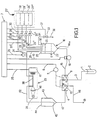
- a means 1 for taking samples draws from a flask 2 (or other equivalent container) containing the sample, a quantity of the same.
- the means 1 for taking sample can also be directly connected to the sample material for continuous monitoring and is connected at the other end through fifth tube 3, to a 2x2-way valve 4 driven by a motor 5.
- a programmer 7 has an output 8 connected to the motor 5 to control its operation. Following actuation of the motor 5, the switch members 9 and 10 are moved from positions 11 and 13 to positions 12 and 14, respectively selecting the apparatus to operate as an open or closed hydraulic circuit.
- the valve 4 is connected by means of a first tube 15 to the bottom input 16a of a first chamber 16.
- the first tube 15 is operatively associated with a peristaltic pump 18 and cooperates with said pump to displace the liquid samples within the apparatus.
- An output 19 of the programmer 7 is connected to the peristaltic pump 18 for the actuation of the same.
- the actuation mode of the pump can define within the circuit of the apparatus according to the present invention a "clockwise" flow direction, from valve 4 towards chamber 16, and a "counterclockwise” flow direction when the liquid within the apparatus according to the present invention is displaced from the chamber 16 towards the valve 4.
- a second tube 21 is inserted into the first chamber 16 through the cover 20, the end 22 of said tube being arranged to draw fluid from within said chamber 16.
- Said first chamber 16 and said cover 20 are sealingly assembled together, i.e. in such a way as to allow an overpressure or negative pressure to be maintained within said chamber.
- the second tube 21 connects the injection chamber 16 to the colorimeter 23 and is operatively associated with the fluid cut-off valve 24.
- the colorimeter can be substituted by another type of detector, without departing from the scope of the present invention. Examples of suitable detectors are photometric, colorimetric, nephelometric, conductometric and/or selective ion detectors. Further, according to the type of determination and the analyte to be determined there can be provided reduction columns, thermostated coils, dialysis units, distillation columns, ionic exchange resins, etc..
- An output 25 and an output 26 of the programmer 7 are connected, respectively, to the colorimeter 23 for signal acquisition and to the cut-off valve 24 for its actuation.
- a container 27 holds a number of compartments 28, 28' .... 28n for reagents or calibrators, said compartments being connected by means of a number of tubes 29, 29' Vietnamese 29n to the first chamber 16 through the cover 20, for the delivery of reagents and/or calibrators, respectively.
- Each tube 29, 29' ... 29n cooperates with a respective cut-off valve 30, 30' ... 30n to adjust and command the delivery of reagents.
- a number of outputs 31, 31' ... 31n of the programmer 7 are connected respectively to each valve 30, 30' ... 30n for their actuation in order to command the consequent delivery of reagents.
- a second valve 33 is arranged close to the injection chamber 16 and cooperates with the elements 34, 35 operating as overflow means. For this purpose the valve 33 cooperates with a tube 34, the end 35 of which draws from the injection chamber 16 at an intermediate point between ends 32, 32' ...32n of the tubes 29, 29' ...29n, and the end 22 of second tube 21.
- the tube 36 connected to the outlet of valve 33, leads to the drain (not shown).
- An output 37 of the programmer 7 is connected to the valve 33 for actuation thereof.
- the second tube 21 is connected to the flow cell 38 within the colorimeter 23, which also contains a light source 39, a condenser 40 and a photodetector 41.
- the flow cell 38 is connected to the fourth tube 42, which enters into the second chamber 43 through the cover 44. Said chamber 43 and said cover 44 are sealingly assembled together, i.e. in such a way as to enable an overpressure or a negative pressure to be maintained therein.
- the exit end 45 of the fourth tube 42 is located inside the second chamber 43.
- the bottom of the chamber 43 is connected by means of the third tube 47 to the 2x2-way valve 4.
- Liquid is taken up by means 1 for taking samples submerged in the flask 2, or in direct contact with the sample to be analyzed, under the action of the peristaltic pump 18.
- the switch member 9 of valve 4 is in position 11, so that fifth tube 3 is connected with first tube 15.
- the sample begins to flow into the first chamber 16, through bottom input 16a, until reaching a level corresponding to the end 22 of the second tube 21.
- the valve 24 is open. Following this, through second tube 21 and valve 24, the sample reaches the colorimeter 23.
- the liquid flows through the second tube 21 until reaching second chamber 43, and, through third tube 47, reaches the valve 4 once again.
- the switch member 10 is in position 13, connecting tube 47 to the drain by means of tube 48.
- the apparatus is selected to operate as an open hydraulic circuit and, a first washing of the apparatus is performed.
- the level of the liquid in injection chamber 16 should be equal to that defined by the end 35 of tube 34.
- the valve 24 is closed and the valve 33 is opened.
- the peristaltic pump 18 which pumps in a clockwise direction, the liquid flows continuously into first chamber 16 until reaching the level defined by the end 35 of tube 34.
- the overflow valve 33 which is open, discharges the excess liquid through end 36 of tube 34 into the drain.
- the valve 33 is closed and the valve 24 is opened.
- the pump 18 continues to suck up the sample through the tube 3 for a time sufficient to guarantee the presence of sample alone within the circuit of the apparatus in question.
- the pump 18 is turned off and at the same time, by means of the programmer 7, the motor 5 moves the switch member 10 from position 13 to position 14 and the switch member 9 from position 11 to position 12, thus setting the apparatus for the measure. At this time the apparatus is selected to operate as a closed circuit.
- sample blank As the whole circuit of the apparatus according to the present invention is now completely filled with the sample, measurement of the "sample blank" can be performed, because the flow cell 38 of the colorimeter 23 is completely filled with said sample.
- the cut-off valve 24 is closed, and the peristaltic pump 18 is actuated in an counterclockwise direction.
- Part of the sample contained in the first chamber 16 is displaced through the 2x2-way valve 4, which is in a measuring position, until reaching second chamber 43. In this way, the liquid is displaced from chamber 16 to chamber 43 without any sample flowing through the inside of the colorimeter 23. Once the liquid inside the first chamber 16 has reached the level 6, the pump 18 is stopped.
- a negative pressure has been set inside the chamber 16 and an overpressure has been produced inside the second chamber 43.
- the valve 30 is opened and the negative pressure inside the chamber 16 causes the dispensing of a metered amount of reagent R 1 or calibrator, contained in the compartment 28, into said chamber 16.
- the opening time of the valve 30 is adjusted, causing dispensing of a metered amount of reagent R 1 or calibrator C 1 according to the type and assumed concentration of analyte under investigation.
- reagent and/or calibrator within the first chamber 16 through the tube 29 produces a reduction of the negative pressure within the chamber 16 and, in order to restore said negative pressure, the peristaltic pump 18 is once again actuated in a counterclockwise direction until level 6 is once again restored inside chamber 16. Following this, and according to the type of analyte, the valve 30' is opened for a period of time sufficient to dispense the required amount of reagent for performance of the measurement reaction. Said reagent R 2 (or calibrator) is transferred from compartment 28', through tube 29', to the inside of the first chamber 16. Once all the required reagents have been delivered inside the chamber 16, the peristaltic pump 18 is actuated in a clockwise direction until the liquid within chamber 16 reaches level 35.
- the reagents and/or calibrators are kept under pressure in the compartments 28, 28', 28n.
- the pressurization in the reagent compartments, upstream of the valves 30, 30', ... 30n, provides an additional guarantee for the working of the injection system.
- the overall volume of liquid contained inside the apparatus is increased by an amount equal to the sum of the amounts of reagents dispensed, thus causing a consequent increase of pressure within the system.
- the switch member 10 of valve 4 is switched from position 14 to position 13, that is to say to drain 49.
- the excess pressure inside the chambers 16 and 43 is eliminated by means of expulsion from second chamber 43 towards the drain 49 of an amount of sample equal to the amount of reagents delivered in chamber 16.
- the switch member 10 of valve 4 is then displaced, again by the action of motor 5, from position 13 to position 14.
- the reagents delivered during the preceding stage in injection chamber 16 are partially diluted in the sample inside chamber 16 itself.
- the peristaltic pump 18 is actuated in a clockwise direction and the circulation of the sample and the reagents begins, allowing a rapid and efficient mixing to take place.
- the variation in absorbancy due to the appearance of reaction products and/or to the disappearance of reagents following development of the chemical reaction is constantly measured, being the flow cell 38 of the colorimeter 23 within the circuit of the apparatus.
- the apparatus On completion of the reaction, the apparatus is adjusted for discharge of the liquid sample contained therein, by displacing, after operation of the motor 5, the switch member 10 of the valve 4 from position 14 to position 13 and, at the same time, actuating the peristaltic pump 18 in a clockwise direction.
- the switch 9 is set to position 11 and is connected by means of tube 3 to the sample or to a supply of washing liquid which thus allows the cleaning of the instrument, while the previous reaction product is being discharged through the tube 48 towards the drain 49. In this way the apparatus is selected to operate as an open hydraulic circuit.
- the apparatus according to the present invention is once again filled with the sample, which is sucked up by means 1 for taking samples, following actuation of the pump 18 in a clockwise direction with switch member 9 of valve 4 set to position 11.
- the first chamber 16 is once again filled up to level 35.
- the sample flows through second tube 21 until reaching the flow cell, passes through it and reaches second chamber 43, pushing the previous reaction product towards the drain.
- the circuit of the apparatus is completely filled with the new sample, and all traces of the previous reaction product have been eliminated. The return to conditions of absence of reaction product can easily be checked by reading data from the colorimeter. At this point the circuit is ready to perform a new cycle of analysis.
- valve 63 Between valve 4 and the peristaltic pump 18, a two-way valve 63 is positioned. In said valve 63, the switch member 62, controlled by the output 61 of the programmer 7, switches between positions 59 and 60.
- valve 4 and the first chamber 16 are in communication; when the switch member 62 is in position 59, the chamber 16 is in communication with the drain 49 through the tube 58 which is connected to the tube 48.
- a two-way valve 64 is connected to position 11 of valve 4 by means of fifth tube 3'.
- the switch member 54 (controlled by output 57 of the programmer 7) of said valve 64 switches between positions 55 and 56.
- the circuit of the apparatus according to the present invention is connected to the flask 52 (or other equivalent recipient) containing washing liquid; when the switch member 54 is in position 55, the circuit of the apparatus according to the present invention is connected to the flask 2' (or other equivalent container) holding the sample with the analytes to be determined.
- the containers holding washing liquid and/or sample with analytes to be determined are more than one.
- evacuation of the circuit of the apparatus according to the present invention is performed.
- the valve 24 is closed and the valve 33 is opened; the switch member 62 in the valve 63 is set to position 59.
- the injection chamber 16 is connected to the drain 49 by means of tubes 58 and 48 and, under the action of the peristaltic pump 18, which pumps in an counterclockwise direction, the contents of first chamber 16 are evacuated.
- valve 64 With the switch member 54 of valve 64 in position 56 it is possible, as an alternative to suction of the sample from flask 2', to suck up a washing liquid from flask 52. After passing through first chamber 16, cut-off valve 24, detector 23 and second chamber 43, the washing liquid reaches valve 4, in which switch member 10 is in position 13 and which is in turn connected, by means of tubes 48' and 48, to the drain 49. In this way washing of the measuring circuit and measurement of the instrument blank is performed.
Landscapes
- General Health & Medical Sciences (AREA)
- Physics & Mathematics (AREA)
- Life Sciences & Earth Sciences (AREA)
- Chemical & Material Sciences (AREA)
- Analytical Chemistry (AREA)
- Biochemistry (AREA)
- Immunology (AREA)
- General Physics & Mathematics (AREA)
- Health & Medical Sciences (AREA)
- Pathology (AREA)
- Automatic Analysis And Handling Materials Therefor (AREA)
- Investigating Or Analysing Biological Materials (AREA)
- Sampling And Sample Adjustment (AREA)
- Optical Measuring Cells (AREA)
Claims (9)
- Vorrichtung zum Bestimmen von Analyten in flüssigen Proben, die umfaßt:eine erste Röhre (15), die mit einer ersten Kammer (16) verbunden ist, wobei die Kammer einem Überdruck und einem Unterdruck in ihrem Inneren widersteht und eine Abdeckung (20) aufweist, die dichtend daran angebracht ist,eine Überlaufeinrichtung (34, 35), die ein Ventil (33) umfaßt und zu der ersten Kammer (16) gehört,einen Reagenzienbehälter (27) für Reagenzien und/oder Kalibratoren, wobei der Reagenzienbehälter (27) in Fluidverbindung mit der ersten Kammer (16) steht,eine Konzentrationsbestimmungseinrichtung (23) zum Bestimmen der Konzentration der Analyte, wobei die Einrichtung über eine zweite Röhre (21) in Fluidverbindung mit der ersten Kammer (16) steht,eine Unterbrechungseinrichtung (24) zum Unterbrechen der Fluidverbindung zwischen der ersten Kammer (16) und der Konzentrationsbestimmungseinrichtung (23),eine dritte Röhre (47), die mit einer zweiten Kammer (43) verbunden ist, wobei die Kammer einem Überdruck und einem Unterdruck in ihrem Inneren widersteht und eine Abdeckung (44) aufweist, die dichtend daran angebracht ist, und wobei die zweite Kammer über eine vierte Röhre (42), die ein Austrittsende (45) aufweist, das im Inneren der zweiten Kammer (43) angeordnet ist, in Fluidverbindung mit der Konzentrationsbestimmungseinrichtung (23) steht,eine Ventileinrichtung (4), über die entweder die erste Röhre (15) mit einer Probe und die dritte Röhre (47) mit einem Abfluß (49) verbunden wird, um so einen offenen hydraulischen Kreis herzustellen, oder die erste Röhre (15) mit der dritten Röhre (47), um so einen geschlossenen hydraulischen Kreis herzustellen,eine Steuereinrichtung (7) zum Betätigen und Steuern der Vorrichtung,eine Zweirichtungs-Pumpeneinrichtung (18), die funktionell mit der ersten Röhre (15) verbunden ist, um die Probe in die erste Kammer (16) zu verdrängen, wenn sie in einer ersten Richtung in dem offenen hydraulischen Kreis betätigt wird, und um Flüssigkeit aus der ersten Kammer (16) in die zweite Kammer (43) zu verdrängen, wenn sie in einer zweiten Richtung in dem geschlossenen hydraulischen Kreis betätigt wird, so daß ein Unterdruck in der ersten Kammer (16) entsteht, der gesteuerte Abgabe der Reagenzien und/oder Kalibratoren in die erste Kammer (16) bewirkt;wobei die Zweirichtungs-Pumpeneinrichtung (18) auch ein Zurückpumpen der flüssigen Proben, die Reagenzien und/oder Kalibratoren enthalten, ermöglicht, wenn sie in dem geschlossenen hydraulischen Kreis betrieben wird;die Zweirichtungs-Pumpeneinrichtung (18) im Zusammenwirken mit der Ventileinrichtung (14) das Entnehmen flüssiger Proben in die Vorrichtung und die Abgabe flüssiger Proben und/oder flüssiger Proben, die Reagenzien und/oder Kalibratoren enthalten, aus der Vorrichtung ermöglicht, wenn sie in dem offenen hydraulischen Kreis betätigt wird.
- Vorrichtung nach Anspruch 1, wobei die Ventileinrichtung (4) durch ein 2x2-Wechselventil gebildet wird.
- Vorrichtung nach Anspruch 1, dadurch gekennzeichnet, daß die Zweirichtungs-Pumpeneinrichtung (18) eine peristaltische Pumpe ist.
- Vorrichtung nach Anspruch 1, wobei der Reagenzbehälter (27) durch eine Reihe separater Zellen (28, 28', 28'' .... 28n) gebildet wird, die jeweils ein Reagens oder einen Kalibrator enthalten und mit der ersten Kammer (16) verbunden sind, wobei zu jeder Zelle ein entsprechendes Absperrventil (30, 30', 30'', ..... 30n) gehört.
- Vorrichtung nach Anspruch 4, wobei in jeder Kammer das entsprechende Reagens und/oder der entsprechende Kalibrator unter Druck gehalten wird.
- Vorrichtung nach Anspruch 1, wobei die Unterbrechungseinrichtung (24) durch ein Absperrventil gebildet wird.
- Vorrichtung nach Anspruch 1, wobei die Konzentrationsbestimmungseinrichtung (23) aus photometrischen und/oder kolorimetrischen Detektoren besteht.
- Vorrichtung nach Anspruch 1, die des weiteren eines oder mehrere Elemente der Klasse enthält, die aus Reduktionssäulen, Thermostatsäulen, Dialyseeinheiten, Kunstharzionenaustauschern besteht, die so angeordnet sind, daß sie mit der Einrichtung zum Bestimmen der Konzentration von Analyten zusammenwirken.
- Verfahren zum Bestimmen von Analyten in flüssigen Proben, das die folgenden Schritte umfaßt:a) Einleiten einer flüssigen Probe, die zu bestimmende Analyte enthält, in eine Vorrichtung, wie sie in Anspruch 1 definiert ist, über eine fünfte Röhre (3, 3') durch die Betätigung der Zweirichtungs-Pumpeneinrichtung (18) und Abgabe der gleichen flüssigen Probe durch Verbindung der dritten Röhre (47) mit dem Abfluß (49), wobei die Vorrichtung als ein offener Kreis arbeitet, so daß die gesamte Vorrichtung ausgewaschen wird und das Vorhandensein der Probe nur in der Vorrichtung gewährleistet ist;b) Einstellen des Pegels der flüssigen Probe im Inneren der ersten Kammer (16) durch Schließen der Unterbrechungseinrichtung (24) und Öffnen des Ventils (33), das zu der Überlaufeinrichtung (34, 35) gehört, um überschüssige Flüssigkeit abzuleiten;c) Ausführen der Vergleichsprobenmessung über die Konzentrationsbestimmungseinrichtung (23), wobei die Vorrichtung als ein geschlossener Kreis arbeitet, das Ventil (33) geschlossen ist und die Unterbrechungseinrichtung (24) offen ist;d) Verschieben eines Volumens der flüssigen Probe, das zwischen dem Pegel der Überlaufeinrichtung (35) und einem Pegel (6) enthalten ist, der so ausgewählt ist, daß das Ende (22) der zweiten Röhre (21) während der Funktion der Vorrichtung in der flüssigen Probe eingetaucht bleibt und daß ein Unterdruck im Inneren der ersten Kammer (16) erzeugt wird, mittels der Zweirichtungs-Pumpeneinrichtung (18) aus der ersten Kammer (16) in die zweite Kammer (43), wobei die Unterbrechungseinrichtung (24) geschlossen ist;e) Zusetzen spezieller Reagenzien und/oder Kalibratoren, die in Zellen (28, 28' ... 28n) enthalten sind, in die erste Kammer (16) über die Wirkung des Unterdrucks, der in der ersten Kammer (16) erzeugt wird;f) Wiederholen von Schrift d) nach etwaigem weiteren Zusetzen von Reagenzien und/oder Kalibratoren;g) Wiederherstellen eines Pegels der flüssigen Probe in der ersten Kammer (16), der dem Pegel der Überlaufeinrichtung (35) entspricht, mittels der Zweirichtungs-Pumpeneinrichtung (18);h) Wiederherstellen des Drucks der vor dem Zusetzen von Reagenzien und/oder Kalibratoren herrschte, im Inneren der Vorrichtung, indem die Vorrichtung als ein offener Kreis betrieben wird und sie über eine Ventileinrichtung (4), die die dritte Röhre (47) mit dem Abfluß verbindet, mit der äußeren Umgebung verbunden wird;i) Mischen der flüssigen Probe mit den Reagenzien und/oder Kalibratoren, indem sie in der Vorrichtung durch die Wirkung der Zweirichtungs-Pumpeneinrichtung (18) umgewälzt werden, wobei die Vorrichtung als ein geschlossener Kreis betrieben wird und die Unterbrechungseinrichtung (24) offen ist;l) kontinuierliches Messen des Ausgangs der Konzentrationsbestimmungseinrichtung (23) während des Ablaufs der Reaktion nach dem Mischen in Schritt i) und Bestimmen der Konzentration der Analyte über die Einrichtung; undm) Abgeben der flüssigen Probe, die die Analyte, Reagenzien und/oder Kalibratoren enthält, durch die Wirkung der Zweirichtungs-Pumpeneinrichtung (18) über eine Ventileinrichtung (4), die die dritte Röhre (47) mit dem Abfluß (49) verbindet, wobei die Vorrichtung als ein offener Kreis betrieben wird.
Applications Claiming Priority (3)
| Application Number | Priority Date | Filing Date | Title |
|---|---|---|---|
| ITRM910601 | 1991-08-06 | ||
| ITRM910601A IT1249433B (it) | 1991-08-06 | 1991-08-06 | Procedimento per il dosaggio di analiti in campioni liquidi e relativaapparecchiatura. |
| PCT/IT1992/000093 WO1993003345A1 (en) | 1991-08-06 | 1992-08-05 | Process and apparatus for the determination of analytes in liquid samples |
Publications (2)
| Publication Number | Publication Date |
|---|---|
| EP0551507A1 EP0551507A1 (de) | 1993-07-21 |
| EP0551507B1 true EP0551507B1 (de) | 2000-10-18 |
Family
ID=11400310
Family Applications (1)
| Application Number | Title | Priority Date | Filing Date |
|---|---|---|---|
| EP92917851A Expired - Lifetime EP0551507B1 (de) | 1991-08-06 | 1992-08-05 | Prozess und apparat zur bestimmung von analyten in flüssigen proben |
Country Status (8)
| Country | Link |
|---|---|
| US (1) | US5411708A (de) |
| EP (1) | EP0551507B1 (de) |
| AT (1) | ATE197093T1 (de) |
| AU (1) | AU2427192A (de) |
| DE (1) | DE69231516T2 (de) |
| ES (1) | ES2152230T3 (de) |
| IT (1) | IT1249433B (de) |
| WO (1) | WO1993003345A1 (de) |
Families Citing this family (49)
| Publication number | Priority date | Publication date | Assignee | Title |
|---|---|---|---|---|
| US6048734A (en) | 1995-09-15 | 2000-04-11 | The Regents Of The University Of Michigan | Thermal microvalves in a fluid flow method |
| US5849592A (en) * | 1997-05-29 | 1998-12-15 | Hach Company | Carrierless sequential injection analysis |
| US6555360B1 (en) * | 1998-03-30 | 2003-04-29 | Friedrich Srienc | Flow injection flow cytometry system for on-line monitoring of biroreactors and method for monitoring |
| US6063634A (en) * | 1998-04-01 | 2000-05-16 | Abbott Laboratories | Fluid assembly and method for diagnostic instrument |
| US6692700B2 (en) | 2001-02-14 | 2004-02-17 | Handylab, Inc. | Heat-reduction methods and systems related to microfluidic devices |
| US7010391B2 (en) | 2001-03-28 | 2006-03-07 | Handylab, Inc. | Methods and systems for control of microfluidic devices |
| US7829025B2 (en) | 2001-03-28 | 2010-11-09 | Venture Lending & Leasing Iv, Inc. | Systems and methods for thermal actuation of microfluidic devices |
| US6852287B2 (en) | 2001-09-12 | 2005-02-08 | Handylab, Inc. | Microfluidic devices having a reduced number of input and output connections |
| US7323140B2 (en) | 2001-03-28 | 2008-01-29 | Handylab, Inc. | Moving microdroplets in a microfluidic device |
| US7270786B2 (en) | 2001-03-28 | 2007-09-18 | Handylab, Inc. | Methods and systems for processing microfluidic samples of particle containing fluids |
| US8895311B1 (en) | 2001-03-28 | 2014-11-25 | Handylab, Inc. | Methods and systems for control of general purpose microfluidic devices |
| US6575188B2 (en) | 2001-07-26 | 2003-06-10 | Handylab, Inc. | Methods and systems for fluid control in microfluidic devices |
| US7192557B2 (en) * | 2001-03-28 | 2007-03-20 | Handylab, Inc. | Methods and systems for releasing intracellular material from cells within microfluidic samples of fluids |
| JP3680167B2 (ja) * | 2001-07-11 | 2005-08-10 | エーザイ株式会社 | 味識別装置及び識別方法 |
| US20040214314A1 (en) * | 2001-11-02 | 2004-10-28 | Friedrich Srienc | High throughput bioreactor |
| ITRM20020356A1 (it) * | 2002-07-03 | 2004-01-05 | Pompeo Moscetta | Apparecchiatura per il dosaggio di analiti contenuti in un campione liquido e relativo procedimento. |
| WO2005011867A2 (en) | 2003-07-31 | 2005-02-10 | Handylab, Inc. | Processing particle-containing samples |
| US8852862B2 (en) | 2004-05-03 | 2014-10-07 | Handylab, Inc. | Method for processing polynucleotide-containing samples |
| WO2005108620A2 (en) | 2004-05-03 | 2005-11-17 | Handylab, Inc. | Processing polynucleotide-containing samples |
| US20060281143A1 (en) * | 2005-04-01 | 2006-12-14 | Msp Corporation | Method and apparatus for automatic cell and biological sample preparation and detection |
| US10900066B2 (en) | 2006-03-24 | 2021-01-26 | Handylab, Inc. | Microfluidic system for amplifying and detecting polynucleotides in parallel |
| US7998708B2 (en) | 2006-03-24 | 2011-08-16 | Handylab, Inc. | Microfluidic system for amplifying and detecting polynucleotides in parallel |
| US8088616B2 (en) | 2006-03-24 | 2012-01-03 | Handylab, Inc. | Heater unit for microfluidic diagnostic system |
| EP3088083B1 (de) | 2006-03-24 | 2018-08-01 | Handylab, Inc. | Methode zur durchführung von pcr mittels einer kartusche mit mehreren bahnen |
| US11806718B2 (en) | 2006-03-24 | 2023-11-07 | Handylab, Inc. | Fluorescence detector for microfluidic diagnostic system |
| US8709787B2 (en) | 2006-11-14 | 2014-04-29 | Handylab, Inc. | Microfluidic cartridge and method of using same |
| WO2008060604A2 (en) | 2006-11-14 | 2008-05-22 | Handylab, Inc. | Microfluidic system for amplifying and detecting polynucleotides in parallel |
| US8105783B2 (en) | 2007-07-13 | 2012-01-31 | Handylab, Inc. | Microfluidic cartridge |
| US20090136385A1 (en) | 2007-07-13 | 2009-05-28 | Handylab, Inc. | Reagent Tube |
| US8133671B2 (en) | 2007-07-13 | 2012-03-13 | Handylab, Inc. | Integrated apparatus for performing nucleic acid extraction and diagnostic testing on multiple biological samples |
| US8287820B2 (en) | 2007-07-13 | 2012-10-16 | Handylab, Inc. | Automated pipetting apparatus having a combined liquid pump and pipette head system |
| US9186677B2 (en) | 2007-07-13 | 2015-11-17 | Handylab, Inc. | Integrated apparatus for performing nucleic acid extraction and diagnostic testing on multiple biological samples |
| US9618139B2 (en) | 2007-07-13 | 2017-04-11 | Handylab, Inc. | Integrated heater and magnetic separator |
| USD621060S1 (en) | 2008-07-14 | 2010-08-03 | Handylab, Inc. | Microfluidic cartridge |
| EP2171460B1 (de) | 2007-07-13 | 2017-08-30 | Handylab, Inc. | Materialien zur erfassung von polynukleotiden und verfahren zu ihrer verwendung |
| US8182763B2 (en) | 2007-07-13 | 2012-05-22 | Handylab, Inc. | Rack for sample tubes and reagent holders |
| US8381169B2 (en) * | 2007-10-30 | 2013-02-19 | International Business Machines Corporation | Extending unified process and method content to include dynamic and collaborative content |
| US8465697B2 (en) * | 2007-12-31 | 2013-06-18 | O.I. Corporation | System and method for regulating flow in fluidic devices |
| USD618820S1 (en) | 2008-07-11 | 2010-06-29 | Handylab, Inc. | Reagent holder |
| USD787087S1 (en) | 2008-07-14 | 2017-05-16 | Handylab, Inc. | Housing |
| US8365616B1 (en) | 2010-09-16 | 2013-02-05 | Wolcott Duane K | Sampling probe for solutions containing soluble solids or high concentrations of dissolved solids |
| AU2012242510B2 (en) | 2011-04-15 | 2015-05-14 | Becton, Dickinson And Company | Scanning real-time microfluidic thermocycler and methods for synchronized thermocycling and scanning optical detection |
| RU2622432C2 (ru) | 2011-09-30 | 2017-06-15 | Бектон, Дикинсон Энд Компани | Унифицированная полоска для реактивов |
| USD692162S1 (en) | 2011-09-30 | 2013-10-22 | Becton, Dickinson And Company | Single piece reagent holder |
| EP2773892B1 (de) | 2011-11-04 | 2020-10-07 | Handylab, Inc. | Vorrichtung zur vorbereitung von polynukleotidproben |
| CN107881219B (zh) | 2012-02-03 | 2021-09-10 | 贝克顿·迪金森公司 | 用于分子诊断测试分配和测试之间兼容性确定的外部文件 |
| CN107907698A (zh) * | 2017-12-14 | 2018-04-13 | 中国科学院深海科学与工程研究所 | 一种用于深海的生物地球化学原位实验装置 |
| CN112156704A (zh) * | 2020-08-18 | 2021-01-01 | 胡森 | 实验室条件下农家肥料中硒元素测定系统 |
| RU2764437C1 (ru) * | 2020-08-20 | 2022-01-17 | Акционерное общество "ТЕХНОЛИНК" | Система автоматической подачи и циркуляции проб суспензий и растворов в проточную измерительную ячейку одноканальных многопоточных анализаторов |
Family Cites Families (14)
| Publication number | Priority date | Publication date | Assignee | Title |
|---|---|---|---|---|
| US3488154A (en) * | 1965-07-02 | 1970-01-06 | Calgon C0Rp | Pressurized flow system |
| US3654113A (en) * | 1969-11-24 | 1972-04-04 | North American Rockwell | Programmed fluid sampling and analysis apparatus |
| ZA784744B (en) * | 1977-08-31 | 1979-08-29 | C Jottier | Apparatus for the treatment of fluids |
| JPS5657954A (en) * | 1979-10-17 | 1981-05-20 | Olympus Optical Co Ltd | Liquid sample diluting apparatus |
| JPS595933A (ja) * | 1982-07-02 | 1984-01-12 | Hitachi Ltd | 液体試料のフロ−分析方法 |
| EP0253519B1 (de) * | 1986-07-11 | 1991-10-09 | Beckman Instruments, Inc. | Probenhandhabungsvorrichtung |
| US5196169A (en) * | 1986-09-02 | 1993-03-23 | Eppendorf North America, Inc. | Method and system for determining free fatty acid content |
| US5230863A (en) * | 1987-07-21 | 1993-07-27 | Si Industrial Instruments, Inc. | Method of calibrating an automatic chemical analyzer |
| US4920056A (en) * | 1988-02-19 | 1990-04-24 | The Dow Chemical Company | Apparatus and method for automated microbatch reaction |
| US5075080A (en) * | 1989-05-19 | 1991-12-24 | Cabot Corporation | Apparatus for measuring the non-porous surface area of carbon black |
| JPH03215742A (ja) * | 1990-01-19 | 1991-09-20 | Tokico Ltd | 金属成分分析装置 |
| JPH03269349A (ja) * | 1990-03-20 | 1991-11-29 | Tokico Ltd | 自動液管理装置 |
| FR2665264A1 (fr) * | 1990-07-24 | 1992-01-31 | Prolabo Sa | Procede pour realiser une reaction chimique par voie humide sur une succession d'echantillons, appareil pour la mise en óoeuvre du procede et utilisation dudit appareil. |
| US5221521A (en) * | 1990-07-26 | 1993-06-22 | Kanzaki Paper Mfg. Co., Ltd. | Sample liquid dilution system for analytical measurements |
-
1991
- 1991-08-06 IT ITRM910601A patent/IT1249433B/it active IP Right Grant
-
1992
- 1992-08-05 AU AU24271/92A patent/AU2427192A/en not_active Abandoned
- 1992-08-05 AT AT92917851T patent/ATE197093T1/de active
- 1992-08-05 DE DE69231516T patent/DE69231516T2/de not_active Expired - Lifetime
- 1992-08-05 US US08/039,101 patent/US5411708A/en not_active Expired - Lifetime
- 1992-08-05 WO PCT/IT1992/000093 patent/WO1993003345A1/en not_active Ceased
- 1992-08-05 ES ES92917851T patent/ES2152230T3/es not_active Expired - Lifetime
- 1992-08-05 EP EP92917851A patent/EP0551507B1/de not_active Expired - Lifetime
Also Published As
| Publication number | Publication date |
|---|---|
| AU2427192A (en) | 1993-03-02 |
| ITRM910601A0 (it) | 1991-08-06 |
| US5411708A (en) | 1995-05-02 |
| WO1993003345A1 (en) | 1993-02-18 |
| ATE197093T1 (de) | 2000-11-15 |
| DE69231516T2 (de) | 2001-03-08 |
| IT1249433B (it) | 1995-02-23 |
| ES2152230T3 (es) | 2001-02-01 |
| ITRM910601A1 (it) | 1993-02-06 |
| EP0551507A1 (de) | 1993-07-21 |
| DE69231516D1 (de) | 2000-11-23 |
Similar Documents
| Publication | Publication Date | Title |
|---|---|---|
| EP0551507B1 (de) | Prozess und apparat zur bestimmung von analyten in flüssigen proben | |
| JP3068202B2 (ja) | シリンダー型シリンジユニットを用いた水質自動分析装置 | |
| US4130394A (en) | Short sample detection | |
| US4066412A (en) | Automatic clinical analyzer | |
| KR910004143B1 (ko) | 뇨(尿)성분의 측정방법과 장치 | |
| EP0098550B1 (de) | Verfahren und Vorrichtung zur Durchfluss-Analyse | |
| US4958295A (en) | Analyzing apparatus and method for analysis of liquid samples | |
| EP0022654A1 (de) | Vorrichtung zum Handhaben von Flüssigkeiten | |
| US3186800A (en) | Automatic titrator | |
| US3419358A (en) | Automatic analysis apparatus and method | |
| GB1299613A (en) | Device for use in measuring automatically a parameter of liquid samples | |
| US4025311A (en) | Programmed fluid sampling and analysis apparatus | |
| US3615230A (en) | Device for automatically carrying out chemical analyses | |
| CN113029955A (zh) | 一种多通道多线程CODcr测量系统 | |
| CN217638303U (zh) | 一种微流控水质检测设备 | |
| JPH06130072A (ja) | 自動分析装置 | |
| KR19980025532A (ko) | 실린더형 시린지 유닛을 이용한 수질의 자동 측정장치 | |
| JPS57149950A (en) | Method for determination of hydrogen peroxide | |
| FI57844B (fi) | Foerfarande foer att foerbaettra kemiska analysers doserings- och maetnoggranhet | |
| AU601980B2 (en) | Analyzing apparatus and method for analysis of liquid samples | |
| EP0787990A4 (de) | Automatischer analysevorrichtung | |
| CN208537406U (zh) | 一种基于微流控技术原位氨氮在线监测仪 | |
| CN106290704A (zh) | 滴定系统及滴定方法 | |
| CN204989129U (zh) | 全密闭式在线电位滴定系统 | |
| US20240035956A1 (en) | Optical analysis system and control method of optical analysis system |
Legal Events
| Date | Code | Title | Description |
|---|---|---|---|
| PUAI | Public reference made under article 153(3) epc to a published international application that has entered the european phase |
Free format text: ORIGINAL CODE: 0009012 |
|
| AK | Designated contracting states |
Kind code of ref document: A1 Designated state(s): AT DE ES FR GB |
|
| 17P | Request for examination filed |
Effective date: 19930729 |
|
| 17Q | First examination report despatched |
Effective date: 19950818 |
|
| GRAG | Despatch of communication of intention to grant |
Free format text: ORIGINAL CODE: EPIDOS AGRA |
|
| GRAG | Despatch of communication of intention to grant |
Free format text: ORIGINAL CODE: EPIDOS AGRA |
|
| GRAH | Despatch of communication of intention to grant a patent |
Free format text: ORIGINAL CODE: EPIDOS IGRA |
|
| GRAH | Despatch of communication of intention to grant a patent |
Free format text: ORIGINAL CODE: EPIDOS IGRA |
|
| GRAA | (expected) grant |
Free format text: ORIGINAL CODE: 0009210 |
|
| AK | Designated contracting states |
Kind code of ref document: B1 Designated state(s): AT DE ES FR GB |
|
| PG25 | Lapsed in a contracting state [announced via postgrant information from national office to epo] |
Ref country code: AT Free format text: LAPSE BECAUSE OF FAILURE TO SUBMIT A TRANSLATION OF THE DESCRIPTION OR TO PAY THE FEE WITHIN THE PRESCRIBED TIME-LIMIT Effective date: 20001018 |
|
| REF | Corresponds to: |
Ref document number: 197093 Country of ref document: AT Date of ref document: 20001115 Kind code of ref document: T |
|
| REF | Corresponds to: |
Ref document number: 69231516 Country of ref document: DE Date of ref document: 20001123 |
|
| REG | Reference to a national code |
Ref country code: ES Ref legal event code: FG2A Ref document number: 2152230 Country of ref document: ES Kind code of ref document: T3 |
|
| RAP2 | Party data changed (patent owner data changed or rights of a patent transferred) |
Owner name: MOSCETTA, POMPEO |
|
| RIN2 | Information on inventor provided after grant (corrected) |
Free format text: MOSCETTA, POMPEO |
|
| ET | Fr: translation filed | ||
| PLBE | No opposition filed within time limit |
Free format text: ORIGINAL CODE: 0009261 |
|
| 26N | No opposition filed | ||
| REG | Reference to a national code |
Ref country code: FR Ref legal event code: CA |
|
| REG | Reference to a national code |
Ref country code: GB Ref legal event code: IF02 |
|
| PGFP | Annual fee paid to national office [announced via postgrant information from national office to epo] |
Ref country code: ES Payment date: 20100825 Year of fee payment: 19 |
|
| PGFP | Annual fee paid to national office [announced via postgrant information from national office to epo] |
Ref country code: FR Payment date: 20100901 Year of fee payment: 19 Ref country code: DE Payment date: 20100823 Year of fee payment: 19 |
|
| PGFP | Annual fee paid to national office [announced via postgrant information from national office to epo] |
Ref country code: GB Payment date: 20100819 Year of fee payment: 19 |
|
| GBPC | Gb: european patent ceased through non-payment of renewal fee |
Effective date: 20110805 |
|
| REG | Reference to a national code |
Ref country code: FR Ref legal event code: ST Effective date: 20120430 |
|
| REG | Reference to a national code |
Ref country code: DE Ref legal event code: R119 Ref document number: 69231516 Country of ref document: DE Effective date: 20120301 |
|
| PG25 | Lapsed in a contracting state [announced via postgrant information from national office to epo] |
Ref country code: GB Free format text: LAPSE BECAUSE OF NON-PAYMENT OF DUE FEES Effective date: 20110805 Ref country code: FR Free format text: LAPSE BECAUSE OF NON-PAYMENT OF DUE FEES Effective date: 20110831 |
|
| REG | Reference to a national code |
Ref country code: ES Ref legal event code: FD2A Effective date: 20130530 |
|
| PG25 | Lapsed in a contracting state [announced via postgrant information from national office to epo] |
Ref country code: DE Free format text: LAPSE BECAUSE OF NON-PAYMENT OF DUE FEES Effective date: 20120301 |
|
| PG25 | Lapsed in a contracting state [announced via postgrant information from national office to epo] |
Ref country code: ES Free format text: LAPSE BECAUSE OF NON-PAYMENT OF DUE FEES Effective date: 20110806 |