EP0551241B1 - Abbildender Spektralapparat mit hoher örtlicher Auflösung - Google Patents
Abbildender Spektralapparat mit hoher örtlicher Auflösung Download PDFInfo
- Publication number
- EP0551241B1 EP0551241B1 EP93630001A EP93630001A EP0551241B1 EP 0551241 B1 EP0551241 B1 EP 0551241B1 EP 93630001 A EP93630001 A EP 93630001A EP 93630001 A EP93630001 A EP 93630001A EP 0551241 B1 EP0551241 B1 EP 0551241B1
- Authority
- EP
- European Patent Office
- Prior art keywords
- mirror
- spherical mirror
- light
- imaging spectrograph
- radiation
- Prior art date
- Legal status (The legal status is an assumption and is not a legal conclusion. Google has not performed a legal analysis and makes no representation as to the accuracy of the status listed.)
- Expired - Lifetime
Links
- 238000003384 imaging method Methods 0.000 title claims description 37
- 230000003595 spectral effect Effects 0.000 claims description 29
- 239000013307 optical fiber Substances 0.000 claims description 17
- 230000005855 radiation Effects 0.000 claims description 14
- 230000003287 optical effect Effects 0.000 claims description 12
- 238000001514 detection method Methods 0.000 claims 7
- 238000013461 design Methods 0.000 description 9
- 201000009310 astigmatism Diseases 0.000 description 7
- 239000000835 fiber Substances 0.000 description 6
- 238000001228 spectrum Methods 0.000 description 5
- 239000011248 coating agent Substances 0.000 description 3
- 238000000576 coating method Methods 0.000 description 3
- 230000001419 dependent effect Effects 0.000 description 3
- 239000006185 dispersion Substances 0.000 description 3
- 238000005259 measurement Methods 0.000 description 3
- 230000004075 alteration Effects 0.000 description 2
- 238000012937 correction Methods 0.000 description 2
- 238000009826 distribution Methods 0.000 description 2
- 230000000694 effects Effects 0.000 description 2
- 206010010071 Coma Diseases 0.000 description 1
- 230000001154 acute effect Effects 0.000 description 1
- 238000004458 analytical method Methods 0.000 description 1
- 238000013459 approach Methods 0.000 description 1
- 238000003491 array Methods 0.000 description 1
- 238000010276 construction Methods 0.000 description 1
- 238000007405 data analysis Methods 0.000 description 1
- 238000013500 data storage Methods 0.000 description 1
- 238000005530 etching Methods 0.000 description 1
- 230000002349 favourable effect Effects 0.000 description 1
- 238000003331 infrared imaging Methods 0.000 description 1
- 238000004519 manufacturing process Methods 0.000 description 1
- 238000000034 method Methods 0.000 description 1
- 238000000386 microscopy Methods 0.000 description 1
- 238000012986 modification Methods 0.000 description 1
- 230000004048 modification Effects 0.000 description 1
- 238000012545 processing Methods 0.000 description 1
- 238000002310 reflectometry Methods 0.000 description 1
- 238000011160 research Methods 0.000 description 1
- 230000035945 sensitivity Effects 0.000 description 1
- 238000004611 spectroscopical analysis Methods 0.000 description 1
- 238000012546 transfer Methods 0.000 description 1
- 238000013519 translation Methods 0.000 description 1
Images

Classifications
-
- G—PHYSICS
- G01—MEASURING; TESTING
- G01J—MEASUREMENT OF INTENSITY, VELOCITY, SPECTRAL CONTENT, POLARISATION, PHASE OR PULSE CHARACTERISTICS OF INFRARED, VISIBLE OR ULTRAVIOLET LIGHT; COLORIMETRY; RADIATION PYROMETRY
- G01J3/00—Spectrometry; Spectrophotometry; Monochromators; Measuring colours
- G01J3/02—Details
- G01J3/0205—Optical elements not provided otherwise, e.g. optical manifolds, diffusers, windows
- G01J3/0208—Optical elements not provided otherwise, e.g. optical manifolds, diffusers, windows using focussing or collimating elements, e.g. lenses or mirrors; performing aberration correction
-
- G—PHYSICS
- G01—MEASURING; TESTING
- G01J—MEASUREMENT OF INTENSITY, VELOCITY, SPECTRAL CONTENT, POLARISATION, PHASE OR PULSE CHARACTERISTICS OF INFRARED, VISIBLE OR ULTRAVIOLET LIGHT; COLORIMETRY; RADIATION PYROMETRY
- G01J3/00—Spectrometry; Spectrophotometry; Monochromators; Measuring colours
- G01J3/02—Details
- G01J3/0205—Optical elements not provided otherwise, e.g. optical manifolds, diffusers, windows
- G01J3/0218—Optical elements not provided otherwise, e.g. optical manifolds, diffusers, windows using optical fibers
- G01J3/0221—Optical elements not provided otherwise, e.g. optical manifolds, diffusers, windows using optical fibers the fibers defining an entry slit
-
- G—PHYSICS
- G01—MEASURING; TESTING
- G01J—MEASUREMENT OF INTENSITY, VELOCITY, SPECTRAL CONTENT, POLARISATION, PHASE OR PULSE CHARACTERISTICS OF INFRARED, VISIBLE OR ULTRAVIOLET LIGHT; COLORIMETRY; RADIATION PYROMETRY
- G01J3/00—Spectrometry; Spectrophotometry; Monochromators; Measuring colours
- G01J3/02—Details
- G01J3/0205—Optical elements not provided otherwise, e.g. optical manifolds, diffusers, windows
- G01J3/0243—Optical elements not provided otherwise, e.g. optical manifolds, diffusers, windows having a through-hole enabling the optical element to fulfil an additional optical function, e.g. a mirror or grating having a throughhole for a light collecting or light injecting optical fiber
-
- G—PHYSICS
- G01—MEASURING; TESTING
- G01J—MEASUREMENT OF INTENSITY, VELOCITY, SPECTRAL CONTENT, POLARISATION, PHASE OR PULSE CHARACTERISTICS OF INFRARED, VISIBLE OR ULTRAVIOLET LIGHT; COLORIMETRY; RADIATION PYROMETRY
- G01J3/00—Spectrometry; Spectrophotometry; Monochromators; Measuring colours
- G01J3/02—Details
- G01J3/0291—Housings; Spectrometer accessories; Spatial arrangement of elements, e.g. folded path arrangements
-
- G—PHYSICS
- G01—MEASURING; TESTING
- G01J—MEASUREMENT OF INTENSITY, VELOCITY, SPECTRAL CONTENT, POLARISATION, PHASE OR PULSE CHARACTERISTICS OF INFRARED, VISIBLE OR ULTRAVIOLET LIGHT; COLORIMETRY; RADIATION PYROMETRY
- G01J3/00—Spectrometry; Spectrophotometry; Monochromators; Measuring colours
- G01J3/28—Investigating the spectrum
- G01J3/2803—Investigating the spectrum using photoelectric array detector
-
- G—PHYSICS
- G01—MEASURING; TESTING
- G01J—MEASUREMENT OF INTENSITY, VELOCITY, SPECTRAL CONTENT, POLARISATION, PHASE OR PULSE CHARACTERISTICS OF INFRARED, VISIBLE OR ULTRAVIOLET LIGHT; COLORIMETRY; RADIATION PYROMETRY
- G01J3/00—Spectrometry; Spectrophotometry; Monochromators; Measuring colours
- G01J3/28—Investigating the spectrum
- G01J3/2823—Imaging spectrometer
-
- G—PHYSICS
- G01—MEASURING; TESTING
- G01J—MEASUREMENT OF INTENSITY, VELOCITY, SPECTRAL CONTENT, POLARISATION, PHASE OR PULSE CHARACTERISTICS OF INFRARED, VISIBLE OR ULTRAVIOLET LIGHT; COLORIMETRY; RADIATION PYROMETRY
- G01J3/00—Spectrometry; Spectrophotometry; Monochromators; Measuring colours
- G01J3/28—Investigating the spectrum
- G01J2003/283—Investigating the spectrum computer-interfaced
Definitions
- the present invention relates to a multichannel spectrograph, and, more particularly, to a spectrograph optimized to provide the largest possible number of independent spatial channels in the vertical plane and more modest spectral resolution in the horizontal plane.
- Spectrographs and more recently scanning monochromators, have been in use for some time in an increasingly large number of applications. However, until quite recently, these instruments were limited to gathering and processing information through one channel. Light entered the instrument from a single source, and the instrument physically separated the light according to its wavelengths and presented as the output a single spectrum, most often dispersed in the horizontal plane.
- dioptric optics were replaced by mirrors, which are easy to produce with broad band reflectivity. While dioptric optics work naturally on axis, mirrors are easier to use at an angle leading to very large astigmatic deformation of the image, an effect that becomes very important with fast instruments which require wide open beams and closely packaged elements.
- a high spatial resolution imaging spectrograph is provided which will provide greatly enhanced spatial resolution for land and sea remote sensing.
- Another object of the present invention is to provide a high spatial resolution imaging spectrograph capable of continuous high speed measurement of spectral distribution information simultaneously at hundreds of points in a sample.
- a high spatial resolution imaging spectrograph in accordance with the present invention provides the highest possible spatial resolution in the vertical plane at the expense of more modest spectral resolution.
- An instrument of the present invention can achieve 400 to 1000 spatial channels at the spectrograph output focal plane. Each such spatial channel is resolved into 100 spectral channels across a wavelength range of, for example, 400-800 nm.
- the information channels can be arranged either to privilege the horizonal, or spectral, direction (as is the case for modern and conventional spectrographs) or the vertical, or spatial, direction (as is the case for a spectrograph in accordance with the present invention).
- FIGURE 3 A high spatial resolution imaging spectrograph provided in accordance with the present invention can be seen in FIGURE 3. Illustrated is a ray-path schematic view of an f/4 instrument capable of providing 400 spatial channels and 100 spectral channels across a wavelength range of 400 to 800 nm.
- a collimating mirror 10 and a focusing mirror 12 are illustrated, each permanently attached to the base of the spectrograph.
- the mirrors are conventional 110 mm diameter spherical mirrors with a focal length of 250 mm facing a plane diffraction grating 14.
- the grating is also permanently affixed to the base of the spectrograph and at an acute angle ⁇ to the perpendicular to the optic axis.
- the angle ⁇ is somewhat dependent upon the grating selected in order not to work too far from the Littrow configuration, which allows for maximum throughput.
- ⁇ will be in the range of 5 to 35 degrees depending on the groove density of the grating.
- the grating 14 is approximately 60 x 60 mm in size.
- An elongated slot 16, 4 x 20 mm in size, is cut through approximately the center of the grating 14, allowing the light source 18 to pass through the slot 16 and onto collimating mirror 10.
- the light source 18 is placed at the focus of the collimating mirror 10 and at a point where radiation can illuminate the collimating mirror.
- Turning mirror 20 is a plane mirror, 10 x 20 mm in size, which also is fixed to the base of the spectrograph and positioned to reflect light from the focus of the focusing mirror 12 onto the camera mirror 22.
- the turning mirror is positioned as close as possible to the elongated slot 16, thus receiving an image as close as possible to the object. This placement of the turning mirror allows the spherical mirrors to work "almost on axis" in an angular range where angular dependent aberrations, particularly astigmatism, are negligible.
- the camera mirror 22 is a conventional 110 mm diameter spherical mirror with a focal length of 150 mm which focuses a final image 25 mm outside the instrument enclosure onto a detector 24. As with the other instrument components, the camera mirror is also fixed to the base of the spectrograph and works "almost on axis".
- the light source to the instrument is preferably provided by an optical fiber ribbon, with individual fiber diameters commonly in a range of 7-250 microns.
- Optical fibers with a diameter of 50 microns provide good spatial resolution and generally acceptable light levels. Larger diameter optical fibers provide more light, but at the expense of less resolution. Smaller diameter fibers limit the number of photons traveling through the fiber, although several layers of smaller diameter fibers (7-20 microns) are also acceptable.
- 400 fibers can each transmit light through the elongated slot 16 in the grating 14, allowing 400 channels of data to be imaged by the instrument.
- the detector 24 will commonly be a CCD or CID 2-D detector array, having commonly the ability to resolve 1028 x 516 pixels. These devices permit the simultaneous measurement of spectral distribution of a spatial profile. Output from the detector is commonly sent through a RS-232 bus connector to a detector controller and then on to a computer for data storage and analysis. Modern detectors offer full programmability in two dimensions, low noise, high quantum efficiency, high dynamic range, and reasonable readout speeds. Further, the configuration of the detectors may be changed by software, an important requirement for a multichannel spectrograph. This is particularly the case for CID detectors where individual pixels are addressable.
- the high spatial resolution imaging spectrograph in accordance with the present invention requires no power input, has no moving parts, and is completely passive with no operating controls or adjustments.
- the various components can be assembled in an instrument enclosure having a footprint of 0.1 m 2 (1.1 ft 2 ) and a volume of less than 0.0198 m 3 (0.7 ft 3 ). Total weight for the system is approximately 10 pounds.
- the instrument as disclosed and illustrated in FIGURE 3 is linearly scalable upward or downward to the desired size.
- a high spatial resolution imaging spectrograph in accordance with the present invention is selected compatible with the spatial resolution requirements of the application.
- Light from the object(s) to be analyzed is brought to the instrument by means of an optical fiber ribbon, which is placed at the focus of the collimating mirror 10.
- Light from individual fibers passes through the elongated slit 16 in the grating 14 and falls onto the collimating mirror 10, which reflects the light in parallel beams onto the grating 14.
- Light diffracted by the grating is collected by the focusing mirror 12, which focuses the light as close as possible to the incoming light from the object and onto the turning mirror 20.
- Light then travels into the camera mirror 22, which then focuses the image in the plane of a detector 24.
- the angle between incoming and outgoing rays onto the collimating mirror 10 and the focusing mirror 12 is limited by the size of the turning mirror 20.
- the size of the turning mirror is defined by the spectral resolution required. The smaller the transverse dimension of the turning mirror, the smaller the number of independent channels of spectral information available and also the smaller the astigmatism introduced by spherical mirrors working slightly off axis, and, hence, the higher the spatial resolution of the instrument.
- a high spatial resolution imaging spectrograph may be designed with a combination mirror 26, which serves both as a collimating mirror and a focusing mirror.
- This mirror, and the other components of the instrument, are the same as discussed above in connection with FIGURE 3, although in this embodiment the grating works very close to the Littrow configuration.
- a high spatial resolution imaging spectrograph is limited in spectral resolution, or throughput, and this design optimizes throughput.
- the instrument can perform adequately with the use of a low dispersion plane diffraction grating, such as a 50 g/mm grating.
- the successive orders of the grating will be close to normal, allowing the functions performed by the collimating and focusing mirrors to be combined in a combination mirror 26.
- the use of a combination mirror allows the grating 14 to be positioned almost perpendicular to the optical axis of the instrument, a favorable configuration to introduce light through the grating.
- the ray path for a combination mirror system is illustrated in FIGURE 4.
- a combination mirror design for a high spatial resolution imaging spectrograph is especially appropriate for applications where the need for spectral resolution is low.
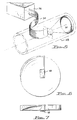
- FIGURE 5 a significant commercial application of the high spatial resolution spectrograph in accordance with the present invention is illustrated, showing an earth science remote imaging system.
- a reflecting telescope 28 of a conventional design is shown, with an optical fiber ribbon 30 mounted vertically at the primary focus 32 of an 20.32 cm (8 inch) primary mirror 34.
- the optical fiber ribbon 30 consists, for example, of 400 50 micron diameter optical fibers affixed together to form a vertical ribbon which is routed into the high spatial imaging spectrograph enclosure 36 and placed at the focus of the collimating mirror.
- the use of an optical fiber ribbon allows for the mechanical decoupling of the two instruments, affording flexibility in the design and use of the system.
- the compact size and light weight of the earth science remote imaging system allows for its use in satellites or aircraft for terrestrial and oceanographic remote sensing research. Further, the use of a flexible optical fiber ribbon between the spectrograph and the telescope provides a soft link between the instruments, which facilitates their placement in the narrow confines of an aircraft or a satellite.
- an airborne or spaceborne system images an elongated area of the ground or sea along the vertical direction of the instrument in order to achieve high definition analysis of features on the surface.
- Spectral data are then collected for each independent spatial channel in a time short enough to use the natural translation of the carrier in the direction perpendicular to the area as a scanning device.
- An optical mask 38 is shown positioned in front of a collimating mirror 10 or a combination mirror 26, in the general shape of the turning mirror 20.
- the mask is carefully positioned in front of the mirror so as to suppress light which would fall on the turning mirror in the first pass of light from the collimating mirror, or combination mirror, to the grating.
- the mask is coated with a non-reflective coating to reduce light falling onto the turning mirror.
- the same effect can be achieved by coating an area of the collimating mirror or combination mirror with a non-reflective coating or etching the surface of the mirror.
Landscapes
- Physics & Mathematics (AREA)
- Spectroscopy & Molecular Physics (AREA)
- General Physics & Mathematics (AREA)
- Spectrometry And Color Measurement (AREA)
Claims (11)
- Abbildender Spektrograph mit:einem ersten sphärischen Spiegel (10);einem zweiten sphärischen Spiegel (12);einem optischen Gitter (14) mit einer langgestreckten Schlitzöffnung (16) darin, das so angeordnet ist, daß es Strahlung von dem ersten sphärischen Spiegel empfängt und auf den zweiten sphärischen Spiegel richtet;einem Lichtumlenkspiegel (20), der benachbart zu der Öffnung (16) und in dem Brennpunkt des zweiten sphärischen Spiegels (12) angeordnet ist, um Strahlung von dem zweiten sphärischen Spiegel zu empfangen;einem dritten sphärischen Spiegel (22), der so angeordnet ist, daß er Strahlung von dem Lichtumlenkspiegel (20) empfängt; und einer Lichterfassungseinrichtung (24) zum Empfangen von Licht von dem dritten sphärischen Spiegel (22);wodurch Strahlung, die von einem Objekt (18) kommt, das in dem Brennpunkt des ersten sphärischen Spiegels (10) angeordnet ist, durch die Öffnung hindurchgeht, um den ersten sphärischen Spiegel zu beleuchten und eine Spektralabbildung auf der Lichterfassungseinrichtung (24) zu bilden.
- Abbildender Spektrograph mit:einem ersten sphärischen Spiegel (26);einem optischen Gitter (14) mit einer langgestreckten Schlitzöffnung (16) darin, das so angeordnet ist, daß es Strahlung von dem ersten sphärischen Spiegel (26) empfängt und richtet und die Strahlung zu dem ersten sphärischen Spiegel (26) zurückleitet;einem Lichtumlenkspiegel (20), der in einem achsenversetzten Brennpunkt des ersten sphärischen Spiegels (26) angeordnet ist;einem zweiten sphärischen Spiegel (22) zum Empfangen von Strahlung von dem Lichtumlenkspiegel (20); undeiner Lichterfassungseinrichtung (24) zum Empfangen von Licht von dem zweiten sphärischen Spiegel (22);wodurch Strahlung, die von einem Objekt kommt, das in dem Brennpunkt des ersten sphärischen Spiegels (26) angeordnet ist, durch die Öffnung (16) hindurchgeht, um den ersten sphärischen Spiegel (26) zu beleuchten und eine Spektralabbildung auf der Lichterfassungseinrichtung (24) zu bilden.
- Abbildender Spektrograph nach Anspruch 1 oder 2, wobei die langgestreckte Schlitzöffnung (16) ungefähr in dem Zentrum des Gitters (14) angeordnet ist.
- Abbildender Spektrograph nach Anspruch 3, wobei das Gitter (14) ein ebenes Beugungsgitter ist.
- Abbildender Spektrograph nach Anspruch 1 oder 2, wobei der Lichtumlenkspiegel ein ebener Spiegel ist, der benachbart zu dem Weg der ankommenden Strahlung angeordnet ist.
- Abbildender Spektrograph nach Anspruch 1 oder 2, wobei die Lichterfassungseinrichtung (24) aus einem zweidimensionalen CCD-Detektor besteht.
- Abbildender Spektrograph nach Anspruch 1 oder 2, wobei die Lichterfassungseinrichtung (24) aus einem zweidimensionalen CID-Detektor besteht.
- Abbildender Spektrograph nach Anspruch 1 oder 2, wobei ein Ende einer Lichtleitfaser in dem Brennpunkt des ersten sphärischen Spiegels (10) angeordnet ist, wodurch Licht aus einem entfernt angeordneten Objekt, das an dem entgegengesetzten Ende der Lichtleitfaser gesammelt wird, als die ankommende Strahlung dienen kann.
- Abbildender Spektrograph nach Anspruch 8, wobei eine Vielzahl von Lichtleitfasern vorgesehen ist, die ein Lichtleitfaserband (30) bilden, wodurch die ankommende Strahlung aus mehreren Kanälen vertikal dargestellter Strahlung besteht und räumlich separate, vertikal dargestellte Spektralabbildungen auf der Lichterfassungseinrichtung gebildet werden.
- Abbildender Spektrograph nach Anspruch 9, wobei ein Ende des Lichtleitfaserbandes (30) in dem Brennpunkt des ersten sphärischen Spiegels (10) angeordnet ist.
- Abbildender Spektrograph nach Anspruch 1 oder 2, weiter mit einer optischen Maske, die so angeordnet ist, daß bei dem ersten Gang von Licht von dem ersten sphärischen Spiegel (10; 26) zu dem Gitter (14) auf den Lichtumlenkspiegel fallende Strahlung unterdrückt wird.
Applications Claiming Priority (2)
| Application Number | Priority Date | Filing Date | Title |
|---|---|---|---|
| US07/819,368 US5305082A (en) | 1992-01-08 | 1992-01-08 | High spatial resolution imaging spectrograph |
| US819368 | 1992-01-08 |
Publications (2)
| Publication Number | Publication Date |
|---|---|
| EP0551241A1 EP0551241A1 (de) | 1993-07-14 |
| EP0551241B1 true EP0551241B1 (de) | 1997-05-28 |
Family
ID=25227965
Family Applications (1)
| Application Number | Title | Priority Date | Filing Date |
|---|---|---|---|
| EP93630001A Expired - Lifetime EP0551241B1 (de) | 1992-01-08 | 1993-01-07 | Abbildender Spektralapparat mit hoher örtlicher Auflösung |
Country Status (4)
| Country | Link |
|---|---|
| US (1) | US5305082A (de) |
| EP (1) | EP0551241B1 (de) |
| CA (1) | CA2086864C (de) |
| DE (1) | DE69310940T2 (de) |
Cited By (1)
| Publication number | Priority date | Publication date | Assignee | Title |
|---|---|---|---|---|
| DE10061765A1 (de) * | 2000-12-12 | 2003-03-06 | Colour Control Farbmestechnik | Mikromechanischer Monochromator mit integrierten Spaltblenden |
Families Citing this family (38)
| Publication number | Priority date | Publication date | Assignee | Title |
|---|---|---|---|---|
| DE4410036B4 (de) * | 1994-03-23 | 2004-09-02 | Berthold Gmbh & Co. Kg | Zweistrahl-Polychromator |
| US6459425B1 (en) | 1997-08-25 | 2002-10-01 | Richard A. Holub | System for automatic color calibration |
| US5757483A (en) * | 1997-08-06 | 1998-05-26 | Stellarnet, Inc. | Dual beam optical spectrograph |
| US6151112A (en) * | 1997-11-17 | 2000-11-21 | Innovative Lasers Corp. | High-resolution, compact intracavity laser spectrometer |
| USH1925H (en) * | 1998-08-18 | 2000-12-05 | The United States Of America As Represented By The Secretary Of The Navy | Apparatus and method for monitoring steel decarburization by remote flame emission spatial imaging spectroscopy |
| DE10131684C1 (de) * | 2001-06-29 | 2002-12-12 | Zeiss Carl Jena Gmbh | Vorrichtung und Verfahren zur ortsaufgelösten Messung einer Schichtdicke |
| US6788407B1 (en) * | 2002-03-18 | 2004-09-07 | Itt Manufacturing Enterprises, Inc. | Laser interrogation of surface agents |
| US6813018B2 (en) * | 2002-11-07 | 2004-11-02 | The Boeing Company | Hyperspectral imager |
| US20050020073A1 (en) * | 2003-07-22 | 2005-01-27 | Lam Research Corporation | Method and system for electronic spatial filtering of spectral reflectometer optical signals |
| US7291824B2 (en) * | 2005-12-22 | 2007-11-06 | Palo Alto Research Center Incorporated | Photosensing throughout energy range and in subranges |
| US7522786B2 (en) * | 2005-12-22 | 2009-04-21 | Palo Alto Research Center Incorporated | Transmitting light with photon energy information |
| US7199877B2 (en) * | 2004-10-20 | 2007-04-03 | Resonon Inc. | Scalable imaging spectrometer |
| US8437582B2 (en) | 2005-12-22 | 2013-05-07 | Palo Alto Research Center Incorporated | Transmitting light with lateral variation |
| US7433552B2 (en) * | 2005-12-22 | 2008-10-07 | Palo Alto Research Center Incorporated | Obtaining analyte information |
| US7547904B2 (en) * | 2005-12-22 | 2009-06-16 | Palo Alto Research Center Incorporated | Sensing photon energies emanating from channels or moving objects |
| US7315667B2 (en) * | 2005-12-22 | 2008-01-01 | Palo Alto Research Center Incorporated | Propagating light to be sensed |
| US7420677B2 (en) * | 2005-12-22 | 2008-09-02 | Palo Alto Research Center Incorporated | Sensing photon energies of optical signals |
| US7358476B2 (en) * | 2005-12-22 | 2008-04-15 | Palo Alto Research Center Incorporated | Sensing photons from objects in channels |
| US7386199B2 (en) * | 2005-12-22 | 2008-06-10 | Palo Alto Research Center Incorporated | Providing light to channels or portions |
| US7345760B2 (en) * | 2006-01-13 | 2008-03-18 | Thermo Electron Scientific Instruments Llc | Grating monochromator/spectrograph |
| US7652792B2 (en) | 2006-03-15 | 2010-01-26 | Quad/Tech, Inc. | Virtual ink desk and method of using same |
| DE102006045624A1 (de) * | 2006-09-27 | 2008-04-03 | Giesecke & Devrient Gmbh | Vorrichtung und Verfahren zur optischen Untersuchung von Wertdokumenten |
| US9164037B2 (en) | 2007-01-26 | 2015-10-20 | Palo Alto Research Center Incorporated | Method and system for evaluation of signals received from spatially modulated excitation and emission to accurately determine particle positions and distances |
| US8821799B2 (en) | 2007-01-26 | 2014-09-02 | Palo Alto Research Center Incorporated | Method and system implementing spatially modulated excitation or emission for particle characterization with enhanced sensitivity |
| US7817274B2 (en) * | 2007-10-05 | 2010-10-19 | Jingyun Zhang | Compact spectrometer |
| US8345226B2 (en) | 2007-11-30 | 2013-01-01 | Jingyun Zhang | Spectrometers miniaturized for working with cellular phones and other portable electronic devices |
| US8320983B2 (en) | 2007-12-17 | 2012-11-27 | Palo Alto Research Center Incorporated | Controlling transfer of objects affecting optical characteristics |
| US8629981B2 (en) | 2008-02-01 | 2014-01-14 | Palo Alto Research Center Incorporated | Analyzers with time variation based on color-coded spatial modulation |
| US8373860B2 (en) | 2008-02-01 | 2013-02-12 | Palo Alto Research Center Incorporated | Transmitting/reflecting emanating light with time variation |
| US8422013B2 (en) * | 2008-11-11 | 2013-04-16 | Bae Systems Information And Electronic Systems Integration Inc. | Optical multiplexer/demultiplexer |
| US9029800B2 (en) | 2011-08-09 | 2015-05-12 | Palo Alto Research Center Incorporated | Compact analyzer with spatial modulation and multiple intensity modulated excitation sources |
| US8723140B2 (en) | 2011-08-09 | 2014-05-13 | Palo Alto Research Center Incorporated | Particle analyzer with spatial modulation and long lifetime bioprobes |
| CN103292902B (zh) * | 2013-05-29 | 2015-04-15 | 南京信息工程大学 | 一种昼气辉温度光度计及其探测气辉光谱强度和温度的方法 |
| CN103776785A (zh) * | 2014-02-20 | 2014-05-07 | 上海师范大学 | 一种集成型便携式超微光谱仪的光学系统 |
| CN105737983B (zh) * | 2016-03-30 | 2017-10-31 | 首都师范大学 | 一种超分重建的斜模高光谱成像地面试验装置及方法 |
| CN108362379B (zh) * | 2018-03-15 | 2023-05-26 | 中国科学院西安光学精密机械研究所 | 一种宽谱段高分辨率光谱色散方法及装置 |
| CN109239916B (zh) * | 2018-10-10 | 2023-09-12 | 中国科学院上海技术物理研究所 | 基于施密特望远镜和奥夫纳分光的高光谱成像仪光学系统 |
| CN114112033B (zh) * | 2021-11-22 | 2024-07-23 | 杭州谱育科技发展有限公司 | 全波段光谱仪及其工作方法 |
Family Cites Families (8)
| Publication number | Priority date | Publication date | Assignee | Title |
|---|---|---|---|---|
| US3025744A (en) * | 1960-01-20 | 1962-03-20 | Barnes Eng Co | Spectrometer |
| US4329050A (en) * | 1979-10-30 | 1982-05-11 | Ball Corporation | Strip-field spectroradiometer |
| DK156381A (da) * | 1980-04-08 | 1981-10-09 | Instruments Sa | Monokromator |
| SU1185113A1 (ru) * | 1983-10-13 | 1985-10-15 | Ленинградский Ордена Трудового Красного Знамени Институт Точной Механики И Оптики | Оптическа система спектрального прибора |
| US4650321A (en) * | 1985-07-05 | 1987-03-17 | The Perkin-Elmer Corporation | Spatial/spectral real time imaging |
| DE3614639A1 (de) * | 1986-04-30 | 1987-11-05 | Messerschmitt Boelkow Blohm | Abbildendes spektrometer |
| JPH02216019A (ja) * | 1989-02-17 | 1990-08-28 | Hitachi Ltd | モノクロメータ |
| US4936684A (en) * | 1989-03-24 | 1990-06-26 | Pacific Scientific Company | Spectrometer with photodetector array detecting uniform bandwidth intervals |
-
1992
- 1992-01-08 US US07/819,368 patent/US5305082A/en not_active Expired - Lifetime
-
1993
- 1993-01-07 EP EP93630001A patent/EP0551241B1/de not_active Expired - Lifetime
- 1993-01-07 DE DE69310940T patent/DE69310940T2/de not_active Expired - Fee Related
- 1993-01-07 CA CA002086864A patent/CA2086864C/en not_active Expired - Fee Related
Cited By (1)
| Publication number | Priority date | Publication date | Assignee | Title |
|---|---|---|---|---|
| DE10061765A1 (de) * | 2000-12-12 | 2003-03-06 | Colour Control Farbmestechnik | Mikromechanischer Monochromator mit integrierten Spaltblenden |
Also Published As
| Publication number | Publication date |
|---|---|
| DE69310940T2 (de) | 1997-09-04 |
| DE69310940D1 (de) | 1997-07-03 |
| CA2086864A1 (en) | 1993-07-09 |
| US5305082A (en) | 1994-04-19 |
| CA2086864C (en) | 1999-11-30 |
| EP0551241A1 (de) | 1993-07-14 |
Similar Documents
| Publication | Publication Date | Title |
|---|---|---|
| EP0551241B1 (de) | Abbildender Spektralapparat mit hoher örtlicher Auflösung | |
| US6100974A (en) | Imaging spectrometer/camera having convex grating | |
| US7518722B2 (en) | Multi-channel, multi-spectrum imaging spectrometer | |
| US5559597A (en) | Spectrograph with multiplexing of different wavelength regions onto a single opto-electric detector array | |
| US7080912B2 (en) | High-resolution, all-reflective imaging spectrometer | |
| US8520204B2 (en) | Dyson-type imaging spectrometer having improved image quality and low distortion | |
| US5260767A (en) | Compact all-reflective imaging spectrometer | |
| US5127728A (en) | Compact prism spectrograph suitable for broadband spectral surveys with array detectors | |
| Hearnshaw et al. | The hercules echelle spectrograph at mt. john | |
| US7262845B2 (en) | Diffractive imaging spectrometer | |
| US7315371B2 (en) | Multi-channel spectrum analyzer | |
| US5768040A (en) | Wide field-of-view imaging spectrometer | |
| US20100238440A1 (en) | Airborne hyperspectral imaging system | |
| Thomas | Toroidal varied-line-space (TVLS) gratings | |
| US5452085A (en) | Spectrographic astigmatism correction system | |
| Thatte et al. | SINFONI: a near-infrared AO-assisted integral field spectrometer for the VLT | |
| Broadfoot et al. | Panchromatic spectrograph with supporting monochromatic imagers | |
| Irani et al. | DeepSpec: a broad-band R~ 650 spectrograph with multiplexing capabilities | |
| Witteborn et al. | A cryogenically cooled, multidetector spectrometer for infrared astronomy | |
| Lepine et al. | SIFUS: SOAR integral field unit spectrograph | |
| US7019833B2 (en) | Miniature optical spectrometer | |
| GB2317446A (en) | Fourier transform spectrometer | |
| Chen et al. | Optical design and wavelength calibration of a DMD-based multi-object spectrograph | |
| Kappelmann et al. | The high resolution spectrograph for spectrum UV | |
| Dopita et al. | WiFeS: the wide field spectrograph |
Legal Events
| Date | Code | Title | Description |
|---|---|---|---|
| PUAI | Public reference made under article 153(3) epc to a published international application that has entered the european phase |
Free format text: ORIGINAL CODE: 0009012 |
|
| AK | Designated contracting states |
Kind code of ref document: A1 Designated state(s): DE FR GB SE |
|
| 17P | Request for examination filed |
Effective date: 19940113 |
|
| 17Q | First examination report despatched |
Effective date: 19950725 |
|
| GRAG | Despatch of communication of intention to grant |
Free format text: ORIGINAL CODE: EPIDOS AGRA |
|
| GRAH | Despatch of communication of intention to grant a patent |
Free format text: ORIGINAL CODE: EPIDOS IGRA |
|
| GRAH | Despatch of communication of intention to grant a patent |
Free format text: ORIGINAL CODE: EPIDOS IGRA |
|
| GRAA | (expected) grant |
Free format text: ORIGINAL CODE: 0009210 |
|
| AK | Designated contracting states |
Kind code of ref document: B1 Designated state(s): DE FR GB SE |
|
| ET | Fr: translation filed | ||
| REF | Corresponds to: |
Ref document number: 69310940 Country of ref document: DE Date of ref document: 19970703 |
|
| PLBE | No opposition filed within time limit |
Free format text: ORIGINAL CODE: 0009261 |
|
| STAA | Information on the status of an ep patent application or granted ep patent |
Free format text: STATUS: NO OPPOSITION FILED WITHIN TIME LIMIT |
|
| 26N | No opposition filed | ||
| REG | Reference to a national code |
Ref country code: GB Ref legal event code: IF02 |
|
| REG | Reference to a national code |
Ref country code: FR Ref legal event code: TP |
|
| REG | Reference to a national code |
Ref country code: GB Ref legal event code: 732E |
|
| PGFP | Annual fee paid to national office [announced via postgrant information from national office to epo] |
Ref country code: FR Payment date: 20051208 Year of fee payment: 14 |
|
| PGFP | Annual fee paid to national office [announced via postgrant information from national office to epo] |
Ref country code: DE Payment date: 20051215 Year of fee payment: 14 |
|
| PGFP | Annual fee paid to national office [announced via postgrant information from national office to epo] |
Ref country code: SE Payment date: 20051221 Year of fee payment: 14 |
|
| PG25 | Lapsed in a contracting state [announced via postgrant information from national office to epo] |
Ref country code: SE Free format text: LAPSE BECAUSE OF NON-PAYMENT OF DUE FEES Effective date: 20070108 |
|
| PG25 | Lapsed in a contracting state [announced via postgrant information from national office to epo] |
Ref country code: DE Free format text: LAPSE BECAUSE OF NON-PAYMENT OF DUE FEES Effective date: 20070801 |
|
| EUG | Se: european patent has lapsed | ||
| REG | Reference to a national code |
Ref country code: FR Ref legal event code: ST Effective date: 20070930 |
|
| PG25 | Lapsed in a contracting state [announced via postgrant information from national office to epo] |
Ref country code: FR Free format text: LAPSE BECAUSE OF NON-PAYMENT OF DUE FEES Effective date: 20070131 |
|
| PGFP | Annual fee paid to national office [announced via postgrant information from national office to epo] |
Ref country code: GB Payment date: 20090122 Year of fee payment: 17 |
|
| GBPC | Gb: european patent ceased through non-payment of renewal fee |
Effective date: 20100107 |
|
| PG25 | Lapsed in a contracting state [announced via postgrant information from national office to epo] |
Ref country code: GB Free format text: LAPSE BECAUSE OF NON-PAYMENT OF DUE FEES Effective date: 20100107 |