EP0549911A1 - Dispositif de surveillance d'une inductivité - Google Patents
Dispositif de surveillance d'une inductivité Download PDFInfo
- Publication number
- EP0549911A1 EP0549911A1 EP92120662A EP92120662A EP0549911A1 EP 0549911 A1 EP0549911 A1 EP 0549911A1 EP 92120662 A EP92120662 A EP 92120662A EP 92120662 A EP92120662 A EP 92120662A EP 0549911 A1 EP0549911 A1 EP 0549911A1
- Authority
- EP
- European Patent Office
- Prior art keywords
- coil
- control
- signal
- circuit
- resonant circuit
- Prior art date
- Legal status (The legal status is an assumption and is not a legal conclusion. Google has not performed a legal analysis and makes no representation as to the accuracy of the status listed.)
- Granted
Links
- 238000012544 monitoring process Methods 0.000 title claims abstract description 7
- 239000000725 suspension Substances 0.000 claims abstract description 25
- 239000003990 capacitor Substances 0.000 claims abstract description 22
- 230000001939 inductive effect Effects 0.000 claims abstract description 7
- 239000004020 conductor Substances 0.000 claims description 2
- 238000002955 isolation Methods 0.000 claims description 2
- 239000000696 magnetic material Substances 0.000 claims description 2
- 238000002347 injection Methods 0.000 claims 1
- 239000007924 injection Substances 0.000 claims 1
- 238000000926 separation method Methods 0.000 description 7
- 238000005259 measurement Methods 0.000 description 6
- 238000010586 diagram Methods 0.000 description 4
- 239000000872 buffer Substances 0.000 description 2
- 230000005669 field effect Effects 0.000 description 2
- 230000004907 flux Effects 0.000 description 2
- 239000004065 semiconductor Substances 0.000 description 2
- 229910000831 Steel Inorganic materials 0.000 description 1
- 239000011149 active material Substances 0.000 description 1
- 238000013459 approach Methods 0.000 description 1
- 238000005452 bending Methods 0.000 description 1
- 238000011109 contamination Methods 0.000 description 1
- 238000001739 density measurement Methods 0.000 description 1
- 230000006698 induction Effects 0.000 description 1
- 238000005339 levitation Methods 0.000 description 1
- 239000000314 lubricant Substances 0.000 description 1
- 238000005461 lubrication Methods 0.000 description 1
- 239000000463 material Substances 0.000 description 1
- 238000000034 method Methods 0.000 description 1
- 239000013641 positive control Substances 0.000 description 1
- 238000012545 processing Methods 0.000 description 1
- 230000002285 radioactive effect Effects 0.000 description 1
- 239000007787 solid Substances 0.000 description 1
- 230000003019 stabilising effect Effects 0.000 description 1
- 239000010959 steel Substances 0.000 description 1
- 231100000331 toxic Toxicity 0.000 description 1
- 230000002588 toxic effect Effects 0.000 description 1
Images


Classifications
-
- F—MECHANICAL ENGINEERING; LIGHTING; HEATING; WEAPONS; BLASTING
- F16—ENGINEERING ELEMENTS AND UNITS; GENERAL MEASURES FOR PRODUCING AND MAINTAINING EFFECTIVE FUNCTIONING OF MACHINES OR INSTALLATIONS; THERMAL INSULATION IN GENERAL
- F16C—SHAFTS; FLEXIBLE SHAFTS; ELEMENTS OR CRANKSHAFT MECHANISMS; ROTARY BODIES OTHER THAN GEARING ELEMENTS; BEARINGS
- F16C32/00—Bearings not otherwise provided for
- F16C32/04—Bearings not otherwise provided for using magnetic or electric supporting means
- F16C32/0406—Magnetic bearings
- F16C32/044—Active magnetic bearings
- F16C32/0444—Details of devices to control the actuation of the electromagnets
- F16C32/0446—Determination of the actual position of the moving member, e.g. details of sensors
- F16C32/0448—Determination of the actual position of the moving member, e.g. details of sensors by using the electromagnet itself as sensor, e.g. sensorless magnetic bearings
-
- G—PHYSICS
- G01—MEASURING; TESTING
- G01D—MEASURING NOT SPECIALLY ADAPTED FOR A SPECIFIC VARIABLE; ARRANGEMENTS FOR MEASURING TWO OR MORE VARIABLES NOT COVERED IN A SINGLE OTHER SUBCLASS; TARIFF METERING APPARATUS; MEASURING OR TESTING NOT OTHERWISE PROVIDED FOR
- G01D5/00—Mechanical means for transferring the output of a sensing member; Means for converting the output of a sensing member to another variable where the form or nature of the sensing member does not constrain the means for converting; Transducers not specially adapted for a specific variable
- G01D5/12—Mechanical means for transferring the output of a sensing member; Means for converting the output of a sensing member to another variable where the form or nature of the sensing member does not constrain the means for converting; Transducers not specially adapted for a specific variable using electric or magnetic means
- G01D5/14—Mechanical means for transferring the output of a sensing member; Means for converting the output of a sensing member to another variable where the form or nature of the sensing member does not constrain the means for converting; Transducers not specially adapted for a specific variable using electric or magnetic means influencing the magnitude of a current or voltage
- G01D5/20—Mechanical means for transferring the output of a sensing member; Means for converting the output of a sensing member to another variable where the form or nature of the sensing member does not constrain the means for converting; Transducers not specially adapted for a specific variable using electric or magnetic means influencing the magnitude of a current or voltage by varying inductance, e.g. by a movable armature
- G01D5/2006—Mechanical means for transferring the output of a sensing member; Means for converting the output of a sensing member to another variable where the form or nature of the sensing member does not constrain the means for converting; Transducers not specially adapted for a specific variable using electric or magnetic means influencing the magnitude of a current or voltage by varying inductance, e.g. by a movable armature by influencing the self-induction of one or more coils
- G01D5/2013—Mechanical means for transferring the output of a sensing member; Means for converting the output of a sensing member to another variable where the form or nature of the sensing member does not constrain the means for converting; Transducers not specially adapted for a specific variable using electric or magnetic means influencing the magnitude of a current or voltage by varying inductance, e.g. by a movable armature by influencing the self-induction of one or more coils by a movable ferromagnetic element, e.g. a core
-
- G—PHYSICS
- G01—MEASURING; TESTING
- G01R—MEASURING ELECTRIC VARIABLES; MEASURING MAGNETIC VARIABLES
- G01R27/00—Arrangements for measuring resistance, reactance, impedance, or electric characteristics derived therefrom
- G01R27/02—Measuring real or complex resistance, reactance, impedance, or other two-pole characteristics derived therefrom, e.g. time constant
- G01R27/26—Measuring inductance or capacitance; Measuring quality factor, e.g. by using the resonance method; Measuring loss factor; Measuring dielectric constants ; Measuring impedance or related variables
- G01R27/2611—Measuring inductance
Definitions
- the present invention relates to apparatus for monitoring the inductance of a coil.
- the present invention may be employed in apparatus for the electromagnetic control of the suspension of an object.
- One aspect of the present invention is concerned with systems for the electromagnetic control of the suspension of an object which are suitable for use in such applications and which systems are of the kind including an electromagnet comprising an inductive control coil, a source of electric power for the electromagnet which source includes a controllable electric supply device capable of delivering a controlled electric supply to the electromagnet, a control signal producer for generating an error control signal in response to an incremental change in a parameter related to the position of the object relative to the electromagnet and a negative feedback control loop for feeding an error control signal generated by the control signal producer to the electric supply device to adjust the electrical supply to the coil so as to stabilise the suspension of the object relative to the electromagnet.
- transducer forming part of the control signal generator for the feedback loop.
- transducers have included devices which are photocells (detecting the interruption of a light beam by movement of the object); magnetic (comprising a gap flux density measurement device, eg Hall plate); inductive (employing two coils in a Maxwell bridge which is in balance when the inductance of the coils is equal); I/B detectors (in which the ratio of the electromagnet coil current and magnetic flux produced is determined to provide a measure of the gap between electromagnet and object; for small disturbances the division may be replaced by a subtraction); and capacitive (employing an oscillator circuit whose output frequency varies with suspension gap).
- the electromagnet coil herein called the "control coil” may be provided on a magnetic core.
- the said object may be any of the objects of types known to be influenced by the magnetic field generated by a current-carrying coil, eg a magnetic material, a permanent magnet, an electromagnet or a current-carrying conductor.
- a current-carrying coil eg a magnetic material, a permanent magnet, an electromagnet or a current-carrying conductor.
- the amplifier of the said amplifier circuit is preferably a high gain amplifier and may be an amplifier of any one of classes A, B, C, D and E.
- the gain of the amplifier is greater than 200, desirably greater than 500.
- the amplitude of the alternating voltage detected by the said amplitude detector may be compared in an error detector with a reference signal comprising a desired mean level, and the error signal comprising variations between the measured amplitude and the desired mean level may be integrated by an integrator and thereafter employed as a control signal in a closed negative feedback loop (which may be in parallel with one or more other loops) connected to the aforementioned controllable electric supply device, eg power amplifier circuit, to adjust the electrical supply to the control coil to maintain the inductance (and impedance) of the control coil at a desired mean level.
- a closed negative feedback loop which may be in parallel with one or more other loops
- resistors in apparatus embodying the invention may be caused by changes in temperature of the operating environment
- resistors may be variable resistors each controlled to have a fixed resistance value over a range of operating temperatures.
- control of position of the object by measurement of the inductance of the control coil in the manner described provides so-called integral control of the suspension of the object which is a known desirable kind of control in which the relationship between the total force acting upon the object and the time integral of the incremental distance moved by the object is a relationship of positive slope.
- control signal producer and feedback loops may be used in conjunction with one or more arrangements comprising feedback loops to provide other forms of control of the suspension of the object by the control coil.
- proportional and/or derivative control of the suspension of the object may also be provided in the manner described in co-pending UK Patent Applications 9200087.6 and 9219959.5 by the present Applicants (the contents of which are incorporated herein by reference), wherein signals representative of the voltage component due to pure inductance across the coil and the current flowing through the coil are obtained and one is differentiated or integrated as appropriate and balanced against the other to derive an error control signal for use in the feedback loop.
- Such a method of control can provide independent proportional and derivative control of the object suspension in addition to the integral control which may be obtained by use of the present invention.
- the present invention allows the problems associated with separate transducers as described hereinbefore to be avoided. Electromagnetic control of the suspension of an object may be achieved at higher temperatures which could otherwise harm the separate transducers as used in the prior art and greater electromagnetic control force per unit area may be obtained by use of the present invention. As the measurement system can be formed by using less discrete parts, suspension control may be achieved more cheaply and more reliably than with prior art systems.
- the signal S1 across the first mentioned or "first" resonant circuit component which is a measure of the a.c. component of the current flowing through the first coil varies with mark-space ratio of the input waveform and also with separation x between the electromagnet comprising the first coil and the object controlled thereby.
- the signal S2 across the further or "second" resonant circuit component which is a measure of the a.c. component of the current flowing through the fourth coil varies only with mark-space ratio of the input waveform.
- Information on the separation x may be obtained by dividing the signal S1 by the signal S2.
- a signal which is representative of the division of the amplitude of S1 by the amplitude of S2 may be employed as the input of the said error detector as specified hereinbefore and the output employed for feedback loop control of the separation x in the manner as described above.
- the said division may be carried out by applying the respective signals S1, S2 picked up from the said first and second resonant circuits to amplitude detectors and then feeding into an operational amplifier the output of the amplitude detector for signal S2 together with the output of a multiplier whose inputs are the output of the amplitude detector for signal S1 and the output of the operational amplifier.
- the fourth coil does not itself form part of a tuned circuit.
- the apparatus according to the present invention may comprise a plurality of control means for controlling together the suspension of an object by controlling its position in the manner described above, each such means comprising a control coil, an electric supply device, an error control signal producer and a feedback loop from the control signal producer to the supply device all as described hereinbefore.
- An active electromagnetic bearing for a rotating shaft constituting the object being suspended may comprise two pairs of electromagnet coils controlled in the manner described the members of each pair working together to control one dimensional suspension, the overall bearing providing two dimensional suspension.
- a complete suspension system for a shaft may comprise two or more such active bearings acting radially upon the shaft and one active thrust bearing acting upon an end of the shaft.
- the core may be shaped and laminated in known manner.
- it may be a solid ring shape with the object at the axis of the ring.
- the ring shape may have projections facing toward the axis some or all of the projections carrying the control coils.
- the core may be one of the other shapes well known in this field.
- the control signal producer for producing an error control signal for each loop may comprise a single circuit common to the feedback loops associated with both coils.
- the control signal producer may have an output which is applied as a negative signal to the electric supply device of one control coil and as a positive signal to the electric supply device of the other control coil and vice versa (as appropriate).
- the output from the common circuit for each feedback loop may be applied in conjunction with an error control signal from a control signal producer dedicated to the control coil with which it is associated.
- Active bearings embodying the present invention may be employed in any applications requiring contactless, maintenance-free, non-lubricated bearings. Such applications include bearings for moving parts in machines handling dangerous materials, eg radioactive, toxic or biologically active materials, high speed bearings for vacuum pumps, food processing (where lubrications would cause contamination), bearings for high temperature environments and bearings for low temperature environments (where oil and other lubricants would freeze).
- dangerous materials eg radioactive, toxic or biologically active materials
- high speed bearings for vacuum pumps where lubrications would cause contamination
- bearings for high temperature environments and bearings for low temperature environments where oil and other lubricants would freeze.
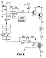
- an electromagnet comprising a control coil represented by its inductance L1 and its resistance R1 is supplied at one of its terminals X1 with a nominally fixed level nominally d.c. supply by a high gain amplifier A1 driving through a resistor R15 a Darlington pair of transistors T1 and T2 connected to a supply voltage +V R .
- Superimposed upon the nominally d.c. output of the amplifier A1 is a 20kHz a.c. signal provided by an oscillator 1 connected to the base of the transistor T1 through a capacitor C3.
- the output of the oscillator 1 and capacitor C3 could alternatively be applied as an input to the amplifier A1.
- the voltage applied to the control coil comprising L1 and R1 contains therefore a 20kHz component of constant voltage amplitude.
- the impedance of the control coil varies with the air gap or separation between the electromagnet comprising the control coil and object being controlled (not shown), and incremental changes in the air gap or separation caused by incremental changes in the total force upon the suspended object result in a varying 20kHz current component passing through the control coil.
- the induced voltage represents a measurement at the applied frequency of the impedance of the control coil and hence any change in the measured induced voltage can be detected to provide control of the gap between the electromagnet comprising the control coil and controlled object.
- the amplitude of the 20kHz component of voltage across the capacitor C2 is detected as follows.
- the voltage is applied via a resistor R20 providing a high input impedance to one input terminal of an amplifier A5 whose other terminal is connected via an isolating capacitor C4 through a resistor R22 to earth.
- a resistor R21 is also connected between the output of the amplifier A5 and the input to the amplifier A5 connected to the capacitor C4.
- the circuit comprising the amplifier A5 acts as a buffer to isolate its output from its input.
- the peak amplitude at the output of the amplifier A5 is detected by a peak level detector 5 and the detected peak level is compared with a reference voltage V REF in an error detector or difference amplifier 7, the difference being provided as an output.
- the output signal from the error detector 7 comprising an error signal is integrated by an integrator 9 whose output ramps until the error signal is zero, and the output of the integrator 9 is applied via a potentiometer P6 and a resistor R23 to the amplifier A1 at an input terminal X3 thereof thereby completing a feedback loop the amplifier A1.
- the other input terminal of the amplifier A1 is connected to earth through a resistor R13.
- the input terminal X3 to the amplifier A1 is also connected through a resistor R121 to the variable contact of a potentiometer P4, the positive end of which is at a positive potential +V and the negative end of which is at a negative potential -V.
- a resistor R14 is connected between the input to the amplifier A1 from the resistor R13 and the output of the amplifier A1.
- control signal applied from the integrator 9 at the terminal X3 is negative so as to increase the gap to its desired mean level to maintain the stable position of the object.
- a positive control signal is applied at the terminal X3 causing the gap to be reduced.
- the level of the reference voltage V REF is selected so as to define the required mean stable gap between the electromagnet and controlled object.
- Circuit Q2 The feedback loop from the transformer M to the input terminal X3 will hereinafter be referred to as "Circuit Q2".
- Control of the suspension of the object by the arrangement comprising the Circuit Q2, as noted above, can be shown to be so-called integral control.
- So-called proportional and/or derivative control of the suspension of the object may also be achieved, eg by an arrangement as described in the aforementioned copending UK Patent Applications and the feedback loop employed in such an arrangement will herein be referred to as "Circuit Q1".
- the Circuits Q1 and Q2 may therefore be in parallel, each generating an error control signal.
- the error control signals generated by the Circuits Q1 and Q2 may be applied together at the terminal X3 as common inputs to the amplifier A1.
- Figures 2 and 3 show alternative ways of deriving the input voltage to the amplifier A5 via resistor R20 in Figure 1.
- the second coil represented by L2 (connected in series with L1) is not part of a transformer but is itself connected to a capacitor C5 selected to give a resonant circuit with the coil L2.
- the voltage across the terminals of coil L2 is isolated via isolating capacitors C6, C7 and forms the input to Circuit Q2 via resistor R20 and amplifier A5 in the manner shown in Figure 1.
- An error control signal (for use in proportional and/or derivative control as in the said copending UK Patent Applications) is generated by the Circuit Q1 with the additional feature, provided by a logic unit (not shown) within Q1 applied to the output of Q1, that where the output to be applied to the amplifier circuit QA is positive the same error control signal but with a negative sign is applied to the amplifier circuit QB, and vice versa.
- an error control signal for use in integral control is generated by the Circuit Q2 in the manner described above with reference to Figure 1, again with the additional feature that this signal is applied both to the amplifier circuit QA and the amplifier circuit QB except that the sense of the signal applied to QA is positive when that applied to QB is negative and vice versa.
- the error control signal outputs of the circuit Q1 shown respectively as A1 and B1 in Figure 4 are equal and of opposite sense, as applied to the respective amplifiers of the amplifier circuits QA, QB, so that the incremental changes required to the input current and voltage applied to the respective coils A, B to provide proportional and/or derivative control of the suspended object are equal and opposite.
- the control signal outputs of the circuit Q2 shown respectively as A2 and B2 are equal and of opposite sense, as applied to the respective amplifiers of the amplifier circuits QA, QB so that the incremental electric supply changes required to the respective coils A, B to give integral control by stabilising the gap between the electromagnet and the controlled object at a selected mean, are equal and opposite.
- Figure 5 shows a circuit embodying the present invention which is a form of circuit alternative to that shown in Figure 1. Items which are the same as in Figure 1 have the same reference numerals.
- the control coil represented by L1 and R1 is energised in a Class D configuration.
- the coil L2 and resistor R2 are again connected in series with the coil represented by L1 and R1 and all are connected between one output terminal of a transistor T3 and one output terminal of a transistor T4.
- the transistors T3 and T4 may be p-n-p or n-p-n bipolar transistors, so the said output terminals may be the collectors or emitters or one of each.
- the transistors T3 and T4 may be replaced by field effect transistors or other semi-conductor devices known by those skilled in the art to be suitable for use in such circuits.
Applications Claiming Priority (4)
| Application Number | Priority Date | Filing Date | Title |
|---|---|---|---|
| GB9200087 | 1992-01-03 | ||
| GB929200087A GB9200087D0 (en) | 1992-01-03 | 1992-01-03 | Apparatus for monitoring inductance |
| GB929222017A GB9222017D0 (en) | 1992-10-20 | 1992-10-20 | Apparatus for monitoring inductance |
| GB9222017 | 1992-10-20 |
Publications (2)
| Publication Number | Publication Date |
|---|---|
| EP0549911A1 true EP0549911A1 (fr) | 1993-07-07 |
| EP0549911B1 EP0549911B1 (fr) | 1997-01-29 |
Family
ID=26300105
Family Applications (1)
| Application Number | Title | Priority Date | Filing Date |
|---|---|---|---|
| EP92120662A Expired - Lifetime EP0549911B1 (fr) | 1992-01-03 | 1992-12-03 | Dispositif de surveillance d'une inductivité |
Country Status (4)
| Country | Link |
|---|---|
| US (1) | US5602711A (fr) |
| EP (1) | EP0549911B1 (fr) |
| JP (1) | JPH05273271A (fr) |
| DE (1) | DE69217194T2 (fr) |
Cited By (9)
| Publication number | Priority date | Publication date | Assignee | Title |
|---|---|---|---|---|
| EP0663538A1 (fr) * | 1993-12-24 | 1995-07-19 | Koyo Seiko Co., Ltd. | Palier magnétique |
| EP0723137A1 (fr) * | 1995-01-17 | 1996-07-24 | Eaton Corporation | Détécteur et régulateur de position à deux fils pour une vanne de néglage de gaz ou pour autres actionneurs électromécanique |
| ES2107948A1 (es) * | 1994-03-17 | 1997-12-01 | Fmc Corp | Dispositivo para medir, sin sensor, el desplazamiento de accionadores electromagneticos. |
| WO1998013612A1 (fr) | 1996-09-24 | 1998-04-02 | British Nuclear Fuels Plc | Dispositif de suspension electromagnetique et procede de commande associe |
| WO2011103406A2 (fr) * | 2010-02-18 | 2011-08-25 | University Of Delaware | Systèmes et procédés de détection d'ondes électromagnétiques |
| US8476900B2 (en) | 2009-05-14 | 2013-07-02 | University Of Delaware | Electromagnetic detection apparatus and methods |
| US8941379B2 (en) | 2009-05-14 | 2015-01-27 | University Of Delaware | Electromagnetic wave detection systems and methods |
| EP2884233A2 (fr) | 2013-12-16 | 2015-06-17 | Eaton Electrical IP GmbH & Co. KG | Mesure de paramètres dans un entraînement électromagnétique d'un appareil de commutation |
| EP2980429A1 (fr) * | 2014-07-28 | 2016-02-03 | Skf Magnetic Mechatronics | Dispositif de détection de position améliorée de biopuce AMB |
Families Citing this family (14)
| Publication number | Priority date | Publication date | Assignee | Title |
|---|---|---|---|---|
| GB9613061D0 (en) * | 1995-09-02 | 1996-08-28 | Magnetic Patent Holdings Ltd | Magnetic suspension system |
| US6208497B1 (en) | 1997-06-26 | 2001-03-27 | Venture Scientifics, Llc | System and method for servo control of nonlinear electromagnetic actuators |
| US6942469B2 (en) | 1997-06-26 | 2005-09-13 | Crystal Investments, Inc. | Solenoid cassette pump with servo controlled volume detection |
| US6128174A (en) * | 1997-08-29 | 2000-10-03 | Stereotaxis, Inc. | Method and apparatus for rapidly changing a magnetic field produced by electromagnets |
| US6982323B1 (en) * | 1997-12-23 | 2006-01-03 | Alexion Pharmaceuticals, Inc. | Chimeric proteins for diagnosis and treatment of diabetes |
| US6373676B1 (en) * | 1998-10-05 | 2002-04-16 | Span Inc. | Magnetic floatation control system |
| US7505545B2 (en) * | 2004-06-24 | 2009-03-17 | Korea Electro Technology Research Institute | Method for recognizing step movement sequence of control rod drive mechanism of nuclear reactor |
| DE102005033151A1 (de) * | 2005-07-13 | 2007-01-18 | Robert Bosch Gmbh | Vorrichtung zur Ansteuerung einer elektromagnetischen Aktuatorik und Verfahren zum Testen einer ersten Induktivität einer elektromagnetischen Aktuatorik |
| US7511478B2 (en) * | 2005-08-03 | 2009-03-31 | Honeywell International Inc. | Sensorless position measurement method for solenoid-based actuation devices using inductance variation |
| US10395781B2 (en) | 2013-06-18 | 2019-08-27 | Analysis And Measurement Services Corporation | In-situ determination of rod control system coil and cable impedances for nuclear power plants |
| US9638763B2 (en) * | 2013-12-31 | 2017-05-02 | Texas Instruments Incorporated | Resonant impedance sensing with a negative impedance control loop implemented with synchronized class D and output comparators |
| CN103825480B (zh) * | 2014-02-25 | 2016-08-17 | 南京航空航天大学 | 一种多路输出的磁轴承开关功放数字单周期控制方法 |
| US10637528B2 (en) * | 2018-07-23 | 2020-04-28 | Audiowise Technology Inc. | Inductor circuit and wireless communication devices |
| IT201900015734A1 (it) * | 2019-09-06 | 2019-12-06 | Brovind Vibratori S P A | Alimentatore vibrante di articoli e procedimento di stima della vita residua dell’elettromagnete di un alimentatore vibrante di articoli. |
Citations (3)
| Publication number | Priority date | Publication date | Assignee | Title |
|---|---|---|---|---|
| DE3150814A1 (de) * | 1981-12-22 | 1983-06-30 | Herion-Werke Kg, 7012 Fellbach | Vorrichtung zur beruehrungslosen bestimmung der schaltstellung des ankers eines elektromagneten |
| FR2565695A1 (fr) * | 1984-06-08 | 1985-12-13 | Europ Propulsion | Procede et dispositif de mesure de la composante reactive d'une impedance complexe |
| FR2624618A1 (fr) * | 1987-12-09 | 1989-06-16 | Herion Werke Kg | Dispositif de mesure de valeurs electromagnetiques d'une bobine et, en particulier, de mesure de la position de l'armature d'un systeme magnetique a bobine/armature |
Family Cites Families (15)
| Publication number | Priority date | Publication date | Assignee | Title |
|---|---|---|---|---|
| GB654394A (en) * | 1942-01-09 | 1951-06-13 | Marc Armand Mercier | Improvements in methods of and means for comparing or measuring the constants of electric circuit elements |
| GB581246A (en) * | 1944-06-07 | 1946-10-07 | Vernon Arthur Sheridan | Improvements in or relating to the measurement of electric impedances |
| GB875869A (en) * | 1958-04-24 | 1961-08-23 | Tno | Improvements relating to measuring circuits |
| GB844360A (en) * | 1959-03-09 | 1960-08-10 | Tesla Np | A resonance meter |
| US3308349A (en) * | 1964-03-13 | 1967-03-07 | Thomas I Kirkpatrick | Magnetic field stabilization |
| US3970925A (en) * | 1974-05-10 | 1976-07-20 | Control Data Corporation | Direct reading reactance meter |
| US4045728A (en) * | 1976-04-15 | 1977-08-30 | Nasa | Direct reading inductance meter |
| US4652820A (en) * | 1983-03-23 | 1987-03-24 | North American Philips Corporation | Combined position sensor and magnetic motor or bearing |
| GB8402470D0 (en) * | 1984-01-31 | 1984-03-07 | Lucas Ind Plc | Drive circuits |
| US4612596A (en) * | 1985-03-18 | 1986-09-16 | Kabushiki Kaisha Toshiba | Circuit for stabilizing electromagnet coil current of a magnetic resonance imaging device |
| US4809742A (en) * | 1988-04-18 | 1989-03-07 | Pneumo Abex Corporation | Control valve assembly including valve position sensor |
| WO1989011105A1 (fr) * | 1988-05-05 | 1989-11-16 | Robert Bosch Gmbh | Circuit mesureur d'inductance variable |
| US5172298A (en) * | 1990-01-09 | 1992-12-15 | Honda Giken Kogyo Kabushiki Kaisha | Electromagnetic actuator |
| DE69223030T2 (de) * | 1992-01-03 | 1998-06-10 | British Nuclear Fuels Plc | Vorrichtung zur Lagesteuerung eines elektromagnetisch gelagerten Objektes |
| US5331277A (en) * | 1992-08-07 | 1994-07-19 | Eldec Corporation | Inductive divider position sensor with fixed and variable impedance inductors |
-
1992
- 1992-12-03 DE DE69217194T patent/DE69217194T2/de not_active Expired - Fee Related
- 1992-12-03 EP EP92120662A patent/EP0549911B1/fr not_active Expired - Lifetime
- 1992-12-25 JP JP4346962A patent/JPH05273271A/ja active Pending
-
1994
- 1994-11-23 US US08/347,066 patent/US5602711A/en not_active Expired - Fee Related
Patent Citations (3)
| Publication number | Priority date | Publication date | Assignee | Title |
|---|---|---|---|---|
| DE3150814A1 (de) * | 1981-12-22 | 1983-06-30 | Herion-Werke Kg, 7012 Fellbach | Vorrichtung zur beruehrungslosen bestimmung der schaltstellung des ankers eines elektromagneten |
| FR2565695A1 (fr) * | 1984-06-08 | 1985-12-13 | Europ Propulsion | Procede et dispositif de mesure de la composante reactive d'une impedance complexe |
| FR2624618A1 (fr) * | 1987-12-09 | 1989-06-16 | Herion Werke Kg | Dispositif de mesure de valeurs electromagnetiques d'une bobine et, en particulier, de mesure de la position de l'armature d'un systeme magnetique a bobine/armature |
Non-Patent Citations (1)
| Title |
|---|
| PATENT ABSTRACTS OF JAPAN vol. 10, no. 357 (M-540)(2414) 2 December 1986 & JP-A-61 153 014 ( HITACHI LTD ) * |
Cited By (15)
| Publication number | Priority date | Publication date | Assignee | Title |
|---|---|---|---|---|
| EP0663538A1 (fr) * | 1993-12-24 | 1995-07-19 | Koyo Seiko Co., Ltd. | Palier magnétique |
| US5736802A (en) * | 1993-12-24 | 1998-04-07 | Koyo Seiko Co., Ltd. | Magnetic bearing device |
| ES2107948A1 (es) * | 1994-03-17 | 1997-12-01 | Fmc Corp | Dispositivo para medir, sin sensor, el desplazamiento de accionadores electromagneticos. |
| US5841621A (en) * | 1994-03-17 | 1998-11-24 | Fmc Corporation | Sensorless measurement of electromagnetic actuator displacement device |
| EP0723137A1 (fr) * | 1995-01-17 | 1996-07-24 | Eaton Corporation | Détécteur et régulateur de position à deux fils pour une vanne de néglage de gaz ou pour autres actionneurs électromécanique |
| WO1998013612A1 (fr) | 1996-09-24 | 1998-04-02 | British Nuclear Fuels Plc | Dispositif de suspension electromagnetique et procede de commande associe |
| US8941379B2 (en) | 2009-05-14 | 2015-01-27 | University Of Delaware | Electromagnetic wave detection systems and methods |
| US8476900B2 (en) | 2009-05-14 | 2013-07-02 | University Of Delaware | Electromagnetic detection apparatus and methods |
| WO2011103406A3 (fr) * | 2010-02-18 | 2011-12-15 | University Of Delaware | Systèmes et procédés de détection d'ondes électromagnétiques |
| WO2011103406A2 (fr) * | 2010-02-18 | 2011-08-25 | University Of Delaware | Systèmes et procédés de détection d'ondes électromagnétiques |
| EP2884233A2 (fr) | 2013-12-16 | 2015-06-17 | Eaton Electrical IP GmbH & Co. KG | Mesure de paramètres dans un entraînement électromagnétique d'un appareil de commutation |
| EP2884233A3 (fr) * | 2013-12-16 | 2015-11-04 | Eaton Electrical IP GmbH & Co. KG | Mesure de paramètres dans un entraînement électromagnétique d'un appareil de commutation |
| EP2980429A1 (fr) * | 2014-07-28 | 2016-02-03 | Skf Magnetic Mechatronics | Dispositif de détection de position améliorée de biopuce AMB |
| CN105318816A (zh) * | 2014-07-28 | 2016-02-10 | Skf磁性机械技术公司 | 主动磁轴承的改进的位置检测装置 |
| US9850945B2 (en) | 2014-07-28 | 2017-12-26 | Skf Magnetic Mechatronics | Position detection device of AMB |
Also Published As
| Publication number | Publication date |
|---|---|
| US5602711A (en) | 1997-02-11 |
| EP0549911B1 (fr) | 1997-01-29 |
| JPH05273271A (ja) | 1993-10-22 |
| DE69217194T2 (de) | 1997-08-21 |
| DE69217194D1 (de) | 1997-03-13 |
Similar Documents
| Publication | Publication Date | Title |
|---|---|---|
| EP0549911B1 (fr) | Dispositif de surveillance d'une inductivité | |
| EP0549912B1 (fr) | Appareil pour le contrÔle de la suspension électromagnétique d'un objet | |
| EP0121007B1 (fr) | Un capteur de position combiné avec un vérin magnétique | |
| US4620752A (en) | Magnetic bearing having triaxial position stabilization | |
| US4991438A (en) | Magnetic fluid rebalance accelerometers | |
| US4866380A (en) | Method and apparatus for determining the distance between an electromagnetic sensor and a conductive rail | |
| US4562430A (en) | Position detection device for magnetic bearing | |
| EP2781888B1 (fr) | Dispositif pour détecter la position d'un organe de travail rotatif dans un palier magnétique actif | |
| CN1544878A (zh) | 一种测量电磁轴承转子轴向位移的方法 | |
| JP3851362B2 (ja) | 電磁アクチュエータ変位装置のセンサ不要な測定装置 | |
| US5748005A (en) | Radial displacement sensor for non-contact bearings | |
| EP0054617B1 (fr) | Paliers magnétiques linéaires | |
| EP0112928A1 (fr) | Detecteur de niveau de toner | |
| EP0478813B1 (fr) | Capteurs de position à recherche de zéro | |
| US3968850A (en) | Electromagnet weighing balance | |
| US5115192A (en) | Magnetic displacement transducer with saturation compensation | |
| US4030085A (en) | Nonferromagnetic linear variable differential transformer | |
| US4658658A (en) | Coil system for inductive measurement of the velocity of movement of a magnetized body | |
| EP0304272A2 (fr) | Détecteur de proximité à induction | |
| EP0178780B1 (fr) | Monitoring du déplacement d'un accouplement de l'arbre | |
| US3478605A (en) | Accelerometer and pickoff system | |
| EP0928373B1 (fr) | Dispositif de suspension electromagnetique et procede de commande associe | |
| US4868499A (en) | Object detector with feedback which holds constant the product of the transmitter coil current and frequency to maintain constant sensor voltage output | |
| JPH02201101A (ja) | 磁気軸受用変位センサ | |
| Yoshida et al. | Self-sensing active magnetic bearings using a new PWM amplifier equipped with a bias voltage source |
Legal Events
| Date | Code | Title | Description |
|---|---|---|---|
| PUAI | Public reference made under article 153(3) epc to a published international application that has entered the european phase |
Free format text: ORIGINAL CODE: 0009012 |
|
| AK | Designated contracting states |
Kind code of ref document: A1 Designated state(s): CH DE FR GB LI |
|
| 17P | Request for examination filed |
Effective date: 19930726 |
|
| 17Q | First examination report despatched |
Effective date: 19950926 |
|
| GRAG | Despatch of communication of intention to grant |
Free format text: ORIGINAL CODE: EPIDOS AGRA |
|
| GRAH | Despatch of communication of intention to grant a patent |
Free format text: ORIGINAL CODE: EPIDOS IGRA |
|
| GRAH | Despatch of communication of intention to grant a patent |
Free format text: ORIGINAL CODE: EPIDOS IGRA |
|
| GRAA | (expected) grant |
Free format text: ORIGINAL CODE: 0009210 |
|
| AK | Designated contracting states |
Kind code of ref document: B1 Designated state(s): CH DE FR GB LI |
|
| PG25 | Lapsed in a contracting state [announced via postgrant information from national office to epo] |
Ref country code: FR Effective date: 19970129 |
|
| REG | Reference to a national code |
Ref country code: CH Ref legal event code: EP |
|
| REG | Reference to a national code |
Ref country code: CH Ref legal event code: NV Representative=s name: E. BLUM & CO. PATENTANWAELTE |
|
| REF | Corresponds to: |
Ref document number: 69217194 Country of ref document: DE Date of ref document: 19970313 |
|
| EN | Fr: translation not filed | ||
| PLBE | No opposition filed within time limit |
Free format text: ORIGINAL CODE: 0009261 |
|
| STAA | Information on the status of an ep patent application or granted ep patent |
Free format text: STATUS: NO OPPOSITION FILED WITHIN TIME LIMIT |
|
| 26N | No opposition filed | ||
| PGFP | Annual fee paid to national office [announced via postgrant information from national office to epo] |
Ref country code: CH Payment date: 19991117 Year of fee payment: 8 |
|
| PGFP | Annual fee paid to national office [announced via postgrant information from national office to epo] |
Ref country code: GB Payment date: 20001120 Year of fee payment: 9 |
|
| PGFP | Annual fee paid to national office [announced via postgrant information from national office to epo] |
Ref country code: DE Payment date: 20001122 Year of fee payment: 9 |
|
| PG25 | Lapsed in a contracting state [announced via postgrant information from national office to epo] |
Ref country code: LI Free format text: LAPSE BECAUSE OF NON-PAYMENT OF DUE FEES Effective date: 20001231 Ref country code: CH Free format text: LAPSE BECAUSE OF NON-PAYMENT OF DUE FEES Effective date: 20001231 |
|
| REG | Reference to a national code |
Ref country code: CH Ref legal event code: PL |
|
| PG25 | Lapsed in a contracting state [announced via postgrant information from national office to epo] |
Ref country code: GB Free format text: LAPSE BECAUSE OF NON-PAYMENT OF DUE FEES Effective date: 20011203 |
|
| REG | Reference to a national code |
Ref country code: GB Ref legal event code: IF02 |
|
| PG25 | Lapsed in a contracting state [announced via postgrant information from national office to epo] |
Ref country code: DE Free format text: LAPSE BECAUSE OF NON-PAYMENT OF DUE FEES Effective date: 20020702 |
|
| GBPC | Gb: european patent ceased through non-payment of renewal fee |
Effective date: 20011203 |