EP0549681B2 - Video image processing - Google Patents
Video image processing Download PDFInfo
- Publication number
- EP0549681B2 EP0549681B2 EP91916977A EP91916977A EP0549681B2 EP 0549681 B2 EP0549681 B2 EP 0549681B2 EP 91916977 A EP91916977 A EP 91916977A EP 91916977 A EP91916977 A EP 91916977A EP 0549681 B2 EP0549681 B2 EP 0549681B2
- Authority
- EP
- European Patent Office
- Prior art keywords
- region
- field
- fields
- vector
- values
- Prior art date
- Legal status (The legal status is an assumption and is not a legal conclusion. Google has not performed a legal analysis and makes no representation as to the accuracy of the status listed.)
- Expired - Lifetime
Links
- 238000012545 processing Methods 0.000 title description 6
- 239000013598 vector Substances 0.000 claims abstract description 141
- 238000000034 method Methods 0.000 claims description 40
- 238000001914 filtration Methods 0.000 claims description 3
- 239000000463 material Substances 0.000 claims 2
- 230000000875 corresponding effect Effects 0.000 description 10
- 230000001934 delay Effects 0.000 description 6
- 238000010586 diagram Methods 0.000 description 5
- 230000002123 temporal effect Effects 0.000 description 5
- 230000006870 function Effects 0.000 description 3
- 230000015654 memory Effects 0.000 description 3
- 230000004044 response Effects 0.000 description 3
- 238000004364 calculation method Methods 0.000 description 2
- 230000000750 progressive effect Effects 0.000 description 2
- 230000003044 adaptive effect Effects 0.000 description 1
- 238000006243 chemical reaction Methods 0.000 description 1
- 230000002596 correlated effect Effects 0.000 description 1
- 238000001514 detection method Methods 0.000 description 1
- 230000000694 effects Effects 0.000 description 1
- 238000013213 extrapolation Methods 0.000 description 1
- 238000004519 manufacturing process Methods 0.000 description 1
- 238000005259 measurement Methods 0.000 description 1
- 238000012805 post-processing Methods 0.000 description 1
- 238000011160 research Methods 0.000 description 1
- 238000012360 testing method Methods 0.000 description 1
Images
Classifications
-
- H—ELECTRICITY
- H04—ELECTRIC COMMUNICATION TECHNIQUE
- H04N—PICTORIAL COMMUNICATION, e.g. TELEVISION
- H04N5/00—Details of television systems
- H04N5/14—Picture signal circuitry for video frequency region
-
- G—PHYSICS
- G06—COMPUTING; CALCULATING OR COUNTING
- G06T—IMAGE DATA PROCESSING OR GENERATION, IN GENERAL
- G06T7/00—Image analysis
- G06T7/20—Analysis of motion
-
- G—PHYSICS
- G06—COMPUTING; CALCULATING OR COUNTING
- G06T—IMAGE DATA PROCESSING OR GENERATION, IN GENERAL
- G06T7/00—Image analysis
- G06T7/20—Analysis of motion
- G06T7/223—Analysis of motion using block-matching
-
- H—ELECTRICITY
- H04—ELECTRIC COMMUNICATION TECHNIQUE
- H04N—PICTORIAL COMMUNICATION, e.g. TELEVISION
- H04N19/00—Methods or arrangements for coding, decoding, compressing or decompressing digital video signals
- H04N19/50—Methods or arrangements for coding, decoding, compressing or decompressing digital video signals using predictive coding
- H04N19/503—Methods or arrangements for coding, decoding, compressing or decompressing digital video signals using predictive coding involving temporal prediction
- H04N19/51—Motion estimation or motion compensation
- H04N19/523—Motion estimation or motion compensation with sub-pixel accuracy
-
- H—ELECTRICITY
- H04—ELECTRIC COMMUNICATION TECHNIQUE
- H04N—PICTORIAL COMMUNICATION, e.g. TELEVISION
- H04N5/00—Details of television systems
- H04N5/14—Picture signal circuitry for video frequency region
- H04N5/144—Movement detection
- H04N5/145—Movement estimation
-
- G—PHYSICS
- G06—COMPUTING; CALCULATING OR COUNTING
- G06T—IMAGE DATA PROCESSING OR GENERATION, IN GENERAL
- G06T2207/00—Indexing scheme for image analysis or image enhancement
- G06T2207/10—Image acquisition modality
- G06T2207/10016—Video; Image sequence
Definitions
- This invention relates to video image processing, and more particularly to the assigning of motion vectors indicating the direction and magnitude of apparent movement to different regions of the image, to assist in the generation of desired output images.
- the motion vectors may be used, for example, to generate output fields which correspond to an instant in time which lies intermediate the time of two input fields. This may be required for instance in producing slow motion effects, in transferring video images to or from film, or in standards coversion.
- One of the most challenging applications of motion compensation is to generate slow-motion sequences without the jerky motion that results from simply repeating each image a number of times.
- Knowledge of the motion vector of each object in the image allows new images corresponding to any time instant to be generated showing the objects correctly positioned.
- the use of such a technique in conjunction with a shuttered CCD camera should allow sharp smoothly-moving pictures to be generated with a quality approaching that obtainable from a high frame-rate camera, without the operational problems that the use of such a camera would entail.
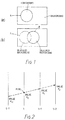
- a typical image may be regarded in its simplest form as having a moving foreground region and a background region, as illustrated somewhat diagrammatically in Figure 1 of the drawings.
- a foreground object such as a ball
- FIG. 1 A typical image may be regarded in its simplest form as having a moving foreground region and a background region, as illustrated somewhat diagrammatically in Figure 1 of the drawings.
- a foreground object such as a ball
- the ball will have moved from position A to position B.
- image (b) part of the background which was seen in (a) is now obscured, and part of the background which was not seen in (a) is now revealed or uncovered.
- the background may also be "moving" in the image if, for example, the camera is being panned.
- motion vectors will be associated both with the foreground and with the background respectively.
- the appropriate motion vector is chosen in each case from the list of possible motion vectors (which has been produced eg. as described in our aforementioned patent) by comparing the two successive fields and looking at the movement which has taken place over different regions of the image.
- This operation will provide accurate information over most of the picture area.
- the background which is not covered by either image position of the ball, A or B, can be compared between the two images.
- the overlap region covered by both position A and position B of the ball can be compared to provide an appropriate vector.
- one of the fields contains an image of the ball and the other an image of the background.
- European Patent Application No. EP-A-0 395 264 published 31st October 1990 describes equipment for converting an 1125/60/2:1 HDTV signal into a 24Hz progressive (non-interlaced) format for recording onto film, which uses a motion estimation technique which comprises a two-stage algorithm in which the first stage comprises correlating (by block matching) relatively large areas of the image to determine a list of possible motion vectors, followed by an assignment process to allocate vectors to individual pixels. In this assignment process, vectors are assigned to pixels in existing input fields, and this information then has to be converted to refer to pixels in desired output fields. Three input frames are used in the comparison.
- EP-A-0 294 961 describes an arrangement in which one of a plurality of motion vectors is assigned to regions of a video image. Four peak vectors are selected for assignment and for each pixel the difference between successive fields is calculated using the four vectors in turn. The vector which gives the minimum error in deriving one field from another is then assigned to that pixel. A third field is only ever used in circumstances where one of the other vectors gererates an error within a preset window from the minimum. Thus the third field is only ever used when testing with the four peak vectors does not give a reliable result.
- an image value for each region of a video image is determined for each of four successive fields, for each one of a list of possible motion vectors.
- the values for the four fields are compared, and when the values are substantally the same for a given vector, it is assumed that that is the vector appropriate to that region.
- the vectors appropriate to regions of obscured or revealed background can also be assigned by comparing inter-field differences and determining regions where the inter-field differences are high for the central pair and one outer pair and low for the other outer pair of the group of four fields.
- Output fields can be generated by interpolation. To generate regions corresponding to obscured background, only information from the earlier fields is used and to generate regions corresponding to revealed background only information from the later fields is used.
- the value of any pixel can be estimated by looking back to the point in the previous field which is displaced by the amount of that vector.
- the value of any pixel can be estimated by looking back to the point in the previous field which is displaced by the amount of that vector.
- taking any given field as a datum one can look backwards and forwards and for each pixel in the datum field generate what value that pixel would be at the time of occurrence of the preceding and subsequent fields. This is achieved by looking at the points in those previous and subsequent fields which are displaced from the pixel in the datum field by an amount appropriate to that motion vector.
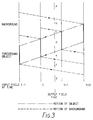
- FIG. 2 diagrammatically illustrates four fields of a video signal at times t - 1, t, t + 1 and t + 2 respectively.
- On the vertical axis is shown in one dimension a spatial section across the image. Due to motion the points that correspond on the different fields are spatially displaced.
- any given motion vector one can build up, for each pixel in the datum field, the values that that pixel is expected to have in a succession of fields. If the motion vector is indeed the correct one for that pixel, those values are likely to be more or less the same. If the operation is repeated for all possible motion vectors, then the vector which produces the least variation in the values obtained is likely to be the appropriate vector for that pixel.
- the values can be processed to give a measure of assignment error, as described below, for each pixel and each vector.
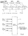
- Figure 3 which likewise diagrammatically illustrates four fields of a video signed at times t - 1, t, t + 1 and t + 2 respectively.
- On the vertical axis is shown in one dimension a foreground object moving over a background which is itself moving. As seen in the figure the foreground object is moving steadily upwards between fields t - 1 and t + 2 whereas the background is moving more slowly downwards.
- the motion vectors may be used in an interpolation operation to generate an output field at an instant t + ⁇ t corresponding to a time intermediate between fields t and t + 1.
- detection of the motion vector is not just more accurate, but also it becomes possible to allocate vectors to the regions c and e of the picture.
- the processing applied to each of the different regions a to g shown on Figure 2 is as follows:
- Regions corresponding to obscured background are generated using only information in preceding fields, and information in areas of revealed background using only following fields.
- the manner in which the assignment errors are generated will now be described.
- Four fields of the video signal are made available simultaneously by suitable storage.
- the four values along the proposed motion trajectory are determined (see Figure 2).
- the values taken are the luminance values of the signal.
- the motion vector may be determined to-an accuracy of better than one pixel and when this is the case the motion trajectory will not pass exactly through existing sample positions on fields t - 1, t + 1 or t + 2.
- a spatial interpolator is then used to calculate the luminance values appertaining to the nearest pixel positions in those fields.
- the four values thus obtained are passed through a high-pass filter which measures the amplitude of the time-varying luminance component.
- Many filter responses are possible but an example of a possible filter response which provides a weighted average of the modulus of the differences is: 0.25 x ⁇
- a value is obtained for each pixel position.
- the values across the image are then smoothed by being applied to a spatial low-pass filter, to form a four-field vector assignment error for each vector.
- the magnitudes of the four-field vector assignment errors for all the possible trial vectors are then compared. If the magnitude of the lowest four-field vector assignment error is below a given threshold, then the corresponding vector is assigned to that pixel and the pixel is flagged as undergoing a simple translational motion.
- the differences between successive fields are examined for all the trial vectors in order to determine which vector and time period gives the lowest error as described above with reference to Figure 3. For example, if the region corresponds to revealed background, then
- the three errors are subjected to a spatial filter and preferably multiplied by weighting factors before they are compared.
- the weighting factors are chosen to ensure that an area is flagged as revealed or obscured background only when the error for one of the outermost field periods is significantly less than for the central period.
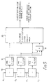
- Figure 4 shows how the four luminance values along a trial motion trajectory may be obtained.
- Three fixed field delays 10 are used to provide signal values from four successive field periods.
- Variable delays 12 are used to perform the shift in accordance with the trial vector value, multiplied by a value corresponding to the time period between the relevant incoming field and the time for which the vector field is being generated.
- Such variable delays can be easily implemented using a number of random-access memories addressed by appropriate read and write pointers.
- each shifter is replaced by a number of shifters to provide the values of surrounding pixels; these values are then fed to a spatial interpolator to perform the sub-pixel part of the shift.
- a spatial interpolator is well-known.
- Figure 5 shows a possible arrangement for calculating four-field and two-field assignment errors from the luminance values calculated in Figure 4.
- the errors are calculated using subtractors 14 followed by circuits 16 to calculate the modulus of the field difference.
- the modulus differences are spatially filtered to form the two-field errors; these are used to calculate the four field error.
- Integrated circuits are available that could be used to perform such spatial filtering; an example is the Inmos A110.
- the four-field error is simply derived in a summer 18 from the sum of the three two-field errors; a more complex high-pass filter arrangement can also be used as explained earlier.
- These errors are passed to a decision circuit 20, which makes a decision based on the values of the errors in relation to each other and to given threshold values and weighting factors as described earlier.
- Such a circuit can be constructed from components such as comparators and logic gates.
- Figure 6 shows how the classification codes and errors associated with each trial vector are compared in order to arrive at a final decision. This involves comparing the errors for each vector using comparators to determine the smallest. The errors may be weighted prior to comparison depending on their classification; such a weighting could be carried out by using a programmable read-only memory 22, addressed by the error value and the classification code. The number indicating the chosen vector may be converted easily into the horizontal and vertical vector components of that vector by using the number to address a look-up table containing the list of trial motion vectors.
- Image interpolation using the vector and classification information obtained as described above may be carried out easily using an arrangement of field delays and variable delays very similar to that shown in Figure 4.
- the variable delays are controlled by the chosen vector; the four luminance values obtained are passed to a four-tap filter whose coefficients are determined by the classification code and the temporal position of the field to be generated.
- a filter may be constructed easily using adders and mutipliers, together with read-only memories to hold the filter coefficients.
- This technique can be used when calculating any of the assignment errors.
- the resulting errors are subject to a spatial low-pass filter as described above.
- a further possible enhancement to the calculation of assignment errors is to include information from the chrominance signal in addition to that from the luminance as described so far.
- Two chrominance assignment errors may be calculated in the same way as described for the luminance, by using the so-called U and V chrominance signals.
- the chrominance assignment errors are then added to that obtained from the luminance component to give a combined assignment error signal which may be more reliable than a luminance-only signal in picture areas with little luminance detail but significant chrominance detail.
- the reliability is improved in this circumstance by repeating the entire assignment process using spatial filters with larger apertures, until a unique vector is found.
- the spatial filtering of the error signals may be performed in parallel using a plurality of filter apertures and the signal from the smallest filter aperture which gives a unique answer is used. If no unique vector can be found which gives a low assignment error, the pixel is then flagged as having an unknown motion.
- match errors are calculated from three unweighted match errors as follows:
- the weighting factors may be constants chosen to optimise the operation of the vector selection process, or may be functions of parameters such as the magnitude of the trial vector, the assignment filter spatial aperture limensions and the output field position.
- first_wt and second_wt are functions which vary in such a way as to reduce problems at object boundaries when background and foreground vectors compete; in such regions the spatial low-pass filter applied to E0-E2 tends to cause the background vector to be selected just inside the edge of the object.
- weighting factors can be limited to a fixed maximum value in the case of very large vectors.
- weighting factors are constants chosen to be smaller than unity and so are always less than first_wt or second_wt. This ensures that vectors representing foreground are favoured in relation to those indicating revealed or obscured background. This is because it is subjectively much better for background around the edge of a moving object to be treated as foreground (becoming slightly blurred) than for edges of a foreground object to be treated as background (causing holes to appear in the object).
- the weighted sums W0-W6 are compared and for each sample the smallest is selected. According to this selection, the vector and area classification are made: If W1, W3, W4, W5 or W6 are the smallest, the corresponding vector as assigned and flagged as foreground. If W0 is the smallest, the corresponding vector is assigned and flagged as obscured background. Similarly if W2 is the smallest, the vector is flagged as representing revealed background. As mentioned previously, if the smallest error is above a preset threshold then the pixel may be flagged as having an unknown vector.
- the vector and area classification information obtained may be subjected to additional post-processing if required: this may include the use of low-pass or median spatial filters. Such filters are well-known.
- the vector and classification information obtained from the operation described above finds particular application in the temporal interpolation of image sequences.
- Such applications include the generation of high quality slow motion replay, standards conversion between different field-rates, and the interpolation of images in film sequences to increase the display rate to that of television.
- an output image is shown as being interpolated at an arbitrary time between existing fields.
- the calculation of the coefficients for the two-field and four-field interpolation filters is a relatively simple and well known process.
- the figure does not show any regions to which no vector could be assigned; such regions are interpolated using a non-adaptive four-tap temporal filter, the response of which may be similar to that of the motion-compensation four-tap filter used in regions a, d and g in Figure 3.
- the vector selection process may be extended to allow up to two vectors to be generated for each output pixel in regions of revealed and obscured background. This allows a soft switch between vectors used for image interpolation at junctions between foreground and background objects. For example, for each pixel that is assigned as revealed background (i.e. the lowest weighted assignment error occurred between the last two fields), the vector giving the minimum assignment error over the first two fields is also determined. The output image is then interpolated from the following fields shifted by the assigned revealed background vector (scaled for the required output time) as previously described, together with a contribution from the preceding fields shifted by this secondary vector.
- a control signal is calculated for each pixel to be interpolated, specifying the fraction of the output image to be taken from the following fields. For all samples in foreground areas, this will be a constant equal to ⁇ t in Figure 3, this being the normal mode of operation of a temporal interpolation filter. In a region flagged as revealed background, the control signal will be set equal to unity, since all information should be taken from following fields as described earlier for region e in Figure 3. This control signal is then subject to a low-pass spatial filter, so that it will no longer be equal to unity just inside regions of revealed background.
Landscapes
- Engineering & Computer Science (AREA)
- Multimedia (AREA)
- Signal Processing (AREA)
- Computer Vision & Pattern Recognition (AREA)
- Physics & Mathematics (AREA)
- General Physics & Mathematics (AREA)
- Theoretical Computer Science (AREA)
- Television Systems (AREA)
- Closed-Circuit Television Systems (AREA)
- Ultra Sonic Daignosis Equipment (AREA)
- Image Processing (AREA)
- Apparatus For Radiation Diagnosis (AREA)
- Silver Salt Photography Or Processing Solution Therefor (AREA)
- Image Analysis (AREA)
- Lubricants (AREA)
- Color Television Image Signal Generators (AREA)
- Lubrication Of Internal Combustion Engines (AREA)
- Cameras Adapted For Combination With Other Photographic Or Optical Apparatuses (AREA)
- Control Of Ac Motors In General (AREA)
- Coating With Molten Metal (AREA)
- Photoreceptors In Electrophotography (AREA)
- Compression Or Coding Systems Of Tv Signals (AREA)
Applications Claiming Priority (5)
| Application Number | Priority Date | Filing Date | Title |
|---|---|---|---|
| GB909020498A GB9020498D0 (en) | 1990-09-20 | 1990-09-20 | Video image processing |
| GB9020498 | 1990-09-20 | ||
| GB9020497 | 1990-09-20 | ||
| GB909020497A GB9020497D0 (en) | 1990-09-20 | 1990-09-20 | Video signal processing |
| PCT/GB1991/001621 WO1992005662A1 (en) | 1990-09-20 | 1991-09-20 | Video image processing |
Publications (3)
| Publication Number | Publication Date |
|---|---|
| EP0549681A1 EP0549681A1 (en) | 1993-07-07 |
| EP0549681B1 EP0549681B1 (en) | 1996-11-27 |
| EP0549681B2 true EP0549681B2 (en) | 2000-03-01 |
Family
ID=26297674
Family Applications (1)
| Application Number | Title | Priority Date | Filing Date |
|---|---|---|---|
| EP91916977A Expired - Lifetime EP0549681B2 (en) | 1990-09-20 | 1991-09-20 | Video image processing |
Country Status (17)
| Country | Link |
|---|---|
| US (1) | US6005639A (hu) |
| EP (1) | EP0549681B2 (hu) |
| JP (1) | JPH06501358A (hu) |
| KR (1) | KR930701888A (hu) |
| CN (1) | CN1063190A (hu) |
| AT (1) | ATE145776T1 (hu) |
| AU (1) | AU643565B2 (hu) |
| BG (1) | BG97555A (hu) |
| BR (1) | BR9106851A (hu) |
| CA (1) | CA2092076A1 (hu) |
| DE (1) | DE69123359T3 (hu) |
| FI (1) | FI931224A0 (hu) |
| GB (1) | GB2261342B (hu) |
| HU (1) | HUT64661A (hu) |
| NO (1) | NO301307B1 (hu) |
| SK (1) | SK399692A3 (hu) |
| WO (1) | WO1992005662A1 (hu) |
Families Citing this family (36)
| Publication number | Priority date | Publication date | Assignee | Title |
|---|---|---|---|---|
| ATE162037T1 (de) * | 1991-05-24 | 1998-01-15 | British Broadcasting Corp | Videobildverarbeitung |
| GB2265783B (en) * | 1992-04-01 | 1996-05-29 | Kenneth Stanley Jones | Bandwidth reduction employing a classification channel |
| GB2279531B (en) * | 1993-06-24 | 1997-07-16 | Sony Uk Ltd | Motion compensated image interpolation |
| US6178265B1 (en) * | 1994-09-22 | 2001-01-23 | Intel Corporation | Method and apparatus for motion vector compression |
| JP3224514B2 (ja) * | 1996-08-21 | 2001-10-29 | シャープ株式会社 | 動画像符号化装置および動画像復号装置 |
| JP3226020B2 (ja) * | 1997-05-28 | 2001-11-05 | 日本電気株式会社 | 動きベクトル検出装置 |
| US6404901B1 (en) * | 1998-01-29 | 2002-06-11 | Canon Kabushiki Kaisha | Image information processing apparatus and its method |
| WO2000011874A1 (de) * | 1998-08-18 | 2000-03-02 | Siemens Aktiengesellschaft | Verfahren und anordnung zur codierung eines digitalisierten bildes mit anwendung eines objektgesamtbewegungsvektors |
| EP1048170A1 (en) | 1998-08-21 | 2000-11-02 | Koninklijke Philips Electronics N.V. | Problem area location in an image signal |
| CN100412905C (zh) * | 1999-12-28 | 2008-08-20 | 索尼公司 | 信号处理方法与设备 |
| JP4106874B2 (ja) | 2001-02-05 | 2008-06-25 | ソニー株式会社 | 画像処理装置および方法、並びに記録媒体 |
| JP4596219B2 (ja) * | 2001-06-25 | 2010-12-08 | ソニー株式会社 | 画像処理装置および方法、記録媒体、並びにプログラム |
| WO2003007618A2 (en) * | 2001-07-10 | 2003-01-23 | Koninklijke Philips Electronics N.V. | Unit for and method of motion estimation and image processing apparatus provided with such motion estimation unit |
| KR100924906B1 (ko) | 2001-11-07 | 2009-11-03 | 엔엑스피 비 브이 | 폐쇄 영역들을 검출하기 위한 폐쇄 검출기 및 방법, 모션 추정기 및 이미지 처리 장치 |
| NL1019365C2 (nl) * | 2001-11-14 | 2003-05-15 | Tno | Bepaling van een beweging van een achtergrond in een reeks beelden. |
| CN1628326A (zh) * | 2002-02-05 | 2005-06-15 | 皇家飞利浦电子股份有限公司 | 通过考虑闭塞估算像素组的运动矢量 |
| JP3840129B2 (ja) * | 2002-03-15 | 2006-11-01 | 株式会社東芝 | 動きベクトル検出方法と装置、補間画像作成方法と装置及び画像表示システム |
| JP2003339029A (ja) * | 2002-05-20 | 2003-11-28 | Sony Corp | 動きベクトル補正回路及び方法 |
| EP1418546A1 (en) * | 2002-11-07 | 2004-05-12 | Mitsubishi Electric Information Technology Centre Europe B.V. | Method and apparatus for representing moving objects in a sequence of images |
| JP2006513661A (ja) * | 2003-01-23 | 2006-04-20 | コーニンクレッカ フィリップス エレクトロニクス エヌ ヴィ | バックグラウンド動きベクトル検出方法及び装置 |
| US7277581B1 (en) * | 2003-08-19 | 2007-10-02 | Nvidia Corporation | Method for video format detection |
| JP4396496B2 (ja) * | 2004-12-02 | 2010-01-13 | 株式会社日立製作所 | フレームレート変換装置、及び映像表示装置、並びにフレームレート変換方法 |
| CN100459693C (zh) * | 2005-11-08 | 2009-02-04 | 逐点半导体(上海)有限公司 | 一种运动补偿插帧装置及插帧方法 |
| JP4303748B2 (ja) * | 2006-02-28 | 2009-07-29 | シャープ株式会社 | 画像表示装置及び方法、画像処理装置及び方法 |
| EP1855474A1 (en) | 2006-05-12 | 2007-11-14 | Sony Deutschland Gmbh | Method for generating an interpolated image between two images of an input image sequence |
| GB0618323D0 (en) | 2006-09-18 | 2006-10-25 | Snell & Wilcox Ltd | Method and apparatus for interpolating an image |
| US7990476B2 (en) * | 2007-09-19 | 2011-08-02 | Samsung Electronics Co., Ltd. | System and method for detecting visual occlusion based on motion vector density |
| CN101953167B (zh) * | 2007-12-20 | 2013-03-27 | 高通股份有限公司 | 减少光晕的图像插值 |
| WO2009085232A1 (en) * | 2007-12-20 | 2009-07-09 | Integrated Device Technology, Inc. | Estimation of true motion vectors using an adaptive search range |
| US8213512B2 (en) * | 2008-05-28 | 2012-07-03 | Cyberlink Corp. | Determining an intermediate image |
| CN101753795B (zh) * | 2008-12-16 | 2012-05-16 | 晨星软件研发(深圳)有限公司 | 用以决定插补画面的移动向量的影像处理方法及其相关装置 |
| EP2224740A1 (en) * | 2009-02-27 | 2010-09-01 | Nxp B.V. | Detecting occlusion |
| ES2586333T3 (es) | 2009-03-30 | 2016-10-13 | Vestel Elektronik Sanayi Ve Ticaret A.S. | Estimación de movimiento de fondo basada en reducción del halo |
| EP2237560A1 (en) | 2009-03-30 | 2010-10-06 | Vestel Elektronik Sanayi ve Ticaret A.S. | Halo reducing motion-compensated interpolation |
| US8537283B2 (en) | 2010-04-15 | 2013-09-17 | Qualcomm Incorporated | High definition frame rate conversion |
| EP2383992B1 (en) * | 2010-04-30 | 2017-11-29 | Vestel Elektronik Sanayi ve Ticaret A.S. | Method and apparatus for the detection and classification of occlusion regions |
Family Cites Families (10)
| Publication number | Priority date | Publication date | Assignee | Title |
|---|---|---|---|---|
| JP2609263B2 (ja) * | 1986-03-19 | 1997-05-14 | ブリティッシュ・ブロードキャスティング・コーポレーション | テレビジョン画像における運動の測定方法及び装置 |
| DE3854337T2 (de) * | 1987-06-09 | 1996-02-01 | Sony Corp | Bewegungskompensierte Interpolation von digitalen Fernsehbildern. |
| DE3851786T2 (de) * | 1987-06-09 | 1995-03-09 | Sony Corp | Auswahl eines Bewegungsvektors in Fernsehbildern. |
| GB8722612D0 (en) * | 1987-09-25 | 1987-11-04 | British Telecomm | Motion estimator |
| US4882613A (en) * | 1987-10-20 | 1989-11-21 | Sanyo Electric Co., Ltd. | Method of and apparatus for motion vector compensation in receiving television signal based on muse system |
| US4979036A (en) * | 1988-05-31 | 1990-12-18 | U.S. Philips Corporation | Television motion detection arrangement |
| GB2231746B (en) * | 1989-04-27 | 1993-07-07 | Sony Corp | Motion dependent video signal processing |
| GB2231743B (en) * | 1989-04-27 | 1993-10-20 | Sony Corp | Motion dependent video signal processing |
| GB2231225B (en) * | 1989-04-27 | 1993-10-20 | Sony Corp | Motion dependent video signal processing |
| US4937666A (en) * | 1989-12-04 | 1990-06-26 | Bell Communications Research, Inc. | Circuit implementation of block matching algorithm with fractional precision |
-
1991
- 1991-09-20 BR BR919106851A patent/BR9106851A/pt unknown
- 1991-09-20 AT AT91916977T patent/ATE145776T1/de active
- 1991-09-20 KR KR1019930700471A patent/KR930701888A/ko not_active Application Discontinuation
- 1991-09-20 EP EP91916977A patent/EP0549681B2/en not_active Expired - Lifetime
- 1991-09-20 HU HU9300004A patent/HUT64661A/hu unknown
- 1991-09-20 SK SK3996-92A patent/SK399692A3/sk unknown
- 1991-09-20 AU AU86245/91A patent/AU643565B2/en not_active Ceased
- 1991-09-20 CA CA002092076A patent/CA2092076A1/en not_active Abandoned
- 1991-09-20 DE DE69123359T patent/DE69123359T3/de not_active Expired - Fee Related
- 1991-09-20 CN CN91108500A patent/CN1063190A/zh active Pending
- 1991-09-20 WO PCT/GB1991/001621 patent/WO1992005662A1/en active IP Right Grant
- 1991-09-20 JP JP3515794A patent/JPH06501358A/ja active Pending
-
1992
- 1992-12-18 GB GB9226485A patent/GB2261342B/en not_active Expired - Fee Related
-
1993
- 1993-03-19 NO NO930999A patent/NO301307B1/no unknown
- 1993-03-19 BG BG097555A patent/BG97555A/bg unknown
- 1993-03-19 FI FI931224A patent/FI931224A0/fi unknown
-
1997
- 1997-08-25 US US08/917,411 patent/US6005639A/en not_active Expired - Fee Related
Also Published As
| Publication number | Publication date |
|---|---|
| CN1063190A (zh) | 1992-07-29 |
| NO930999L (no) | 1993-03-19 |
| AU643565B2 (en) | 1993-11-18 |
| DE69123359D1 (de) | 1997-01-09 |
| SK399692A3 (en) | 1995-01-05 |
| CA2092076A1 (en) | 1992-03-21 |
| DE69123359T2 (de) | 1997-06-12 |
| GB2261342B (en) | 1994-11-02 |
| BR9106851A (pt) | 1993-06-15 |
| JPH06501358A (ja) | 1994-02-10 |
| WO1992005662A1 (en) | 1992-04-02 |
| EP0549681A1 (en) | 1993-07-07 |
| HUT64661A (en) | 1994-01-28 |
| GB9226485D0 (en) | 1993-03-10 |
| EP0549681B1 (en) | 1996-11-27 |
| NO930999D0 (no) | 1993-03-19 |
| FI931224A (fi) | 1993-03-19 |
| GB2261342A (en) | 1993-05-12 |
| FI931224A0 (fi) | 1993-03-19 |
| HU9300004D0 (en) | 1993-04-28 |
| ATE145776T1 (de) | 1996-12-15 |
| US6005639A (en) | 1999-12-21 |
| KR930701888A (ko) | 1993-06-12 |
| NO301307B1 (no) | 1997-10-06 |
| AU8624591A (en) | 1992-04-15 |
| DE69123359T3 (de) | 2000-06-08 |
| BG97555A (bg) | 1993-12-24 |
Similar Documents
| Publication | Publication Date | Title |
|---|---|---|
| EP0549681B2 (en) | Video image processing | |
| Dubois et al. | Noise reduction in image sequences using motion-compensated temporal filtering | |
| US5488421A (en) | Interlaced-to-progressive scanning converter with a double-smoother and a method therefor | |
| US5642170A (en) | Method and apparatus for motion compensated interpolation of intermediate fields or frames | |
| US4862267A (en) | Motion compensated interpolation of digital television images | |
| US5526053A (en) | Motion compensated video signal processing | |
| US20100271554A1 (en) | Method And Apparatus For Motion Estimation In Video Image Data | |
| US5444493A (en) | Method and apparatus for providing intra-field interpolation of video signals with adaptive weighting based on gradients of temporally adjacent fields | |
| US4862260A (en) | Motion vector processing in television images | |
| US5386248A (en) | Method and apparatus for reducing motion estimator hardware and data transmission capacity requirements in video systems | |
| JP4197434B2 (ja) | 動き推定の容易化 | |
| EP0817478A1 (en) | Process for interpolating frames for film mode compatibility | |
| KR100269908B1 (ko) | 움직임 보상 화상 포맷 변환 방법 | |
| GB2312806A (en) | Motion compensated video signal interpolation | |
| Blume | New algorithm for nonlinear vector-based upconversion with center weighted medians | |
| JP3121519B2 (ja) | 動きベクトルを用いた動き内挿方法および動き内挿回路ならびに動きベクトル検出方法および動きベクトル検出回路 | |
| JP2770300B2 (ja) | 画像信号処理処置 | |
| JP2938677B2 (ja) | 動き補償予測方法 | |
| EP0648046A2 (en) | Method and apparatus for motion compensated interpolation of intermediate fields or frames | |
| JPH0414980A (ja) | テレビジョン信号内挿方式 | |
| JP3831960B2 (ja) | 圧縮高解像度ビデオ信号の補間装置および補間方法 | |
| KR950005648B1 (ko) | 뮤즈 디코더(muse decoder)의 필드간(間) 내삽회로 | |
| JPH0455030B2 (hu) | ||
| EP0474272A1 (en) | Method and apparatus for reducing motion estimator hardware and data transmission capacity requirements in video systems | |
| Ernst et al. | Advanced motion estimation for standards conversion and slow motion |
Legal Events
| Date | Code | Title | Description |
|---|---|---|---|
| PUAI | Public reference made under article 153(3) epc to a published international application that has entered the european phase |
Free format text: ORIGINAL CODE: 0009012 |
|
| 17P | Request for examination filed |
Effective date: 19921002 |
|
| AK | Designated contracting states |
Kind code of ref document: A1 Designated state(s): AT BE CH DE DK ES FR GR IT LI LU NL SE |
|
| 17Q | First examination report despatched |
Effective date: 19950119 |
|
| GRAG | Despatch of communication of intention to grant |
Free format text: ORIGINAL CODE: EPIDOS AGRA |
|
| GRAH | Despatch of communication of intention to grant a patent |
Free format text: ORIGINAL CODE: EPIDOS IGRA |
|
| GRAH | Despatch of communication of intention to grant a patent |
Free format text: ORIGINAL CODE: EPIDOS IGRA |
|
| GRAA | (expected) grant |
Free format text: ORIGINAL CODE: 0009210 |
|
| AK | Designated contracting states |
Kind code of ref document: B1 Designated state(s): AT BE CH DE DK ES FR GR IT LI LU NL SE |
|
| ITF | It: translation for a ep patent filed | ||
| PG25 | Lapsed in a contracting state [announced via postgrant information from national office to epo] |
Ref country code: NL Free format text: LAPSE BECAUSE OF FAILURE TO SUBMIT A TRANSLATION OF THE DESCRIPTION OR TO PAY THE FEE WITHIN THE PRESCRIBED TIME-LIMIT Effective date: 19961127 Ref country code: LI Effective date: 19961127 Ref country code: GR Free format text: LAPSE BECAUSE OF FAILURE TO SUBMIT A TRANSLATION OF THE DESCRIPTION OR TO PAY THE FEE WITHIN THE PRESCRIBED TIME-LIMIT Effective date: 19961127 Ref country code: ES Free format text: THE PATENT HAS BEEN ANNULLED BY A DECISION OF A NATIONAL AUTHORITY Effective date: 19961127 Ref country code: DK Effective date: 19961127 Ref country code: CH Effective date: 19961127 Ref country code: AT Effective date: 19961127 |
|
| REF | Corresponds to: |
Ref document number: 145776 Country of ref document: AT Date of ref document: 19961215 Kind code of ref document: T |
|
| REF | Corresponds to: |
Ref document number: 69123359 Country of ref document: DE Date of ref document: 19970109 |
|
| ITF | It: translation for a ep patent filed | ||
| ET | Fr: translation filed | ||
| PG25 | Lapsed in a contracting state [announced via postgrant information from national office to epo] |
Ref country code: SE Effective date: 19970227 |
|
| NLV1 | Nl: lapsed or annulled due to failure to fulfill the requirements of art. 29p and 29m of the patents act | ||
| REG | Reference to a national code |
Ref country code: CH Ref legal event code: PL |
|
| PLBI | Opposition filed |
Free format text: ORIGINAL CODE: 0009260 |
|
| PLBQ | Unpublished change to opponent data |
Free format text: ORIGINAL CODE: EPIDOS OPPO |
|
| PG25 | Lapsed in a contracting state [announced via postgrant information from national office to epo] |
Ref country code: LU Free format text: LAPSE BECAUSE OF NON-PAYMENT OF DUE FEES Effective date: 19970930 |
|
| PLBF | Reply of patent proprietor to notice(s) of opposition |
Free format text: ORIGINAL CODE: EPIDOS OBSO |
|
| 26 | Opposition filed |
Opponent name: INTERESSENGEMEINSCHAFT FUER RUNDFUNKSCHUTZRECHTE G Effective date: 19970826 |
|
| PLBF | Reply of patent proprietor to notice(s) of opposition |
Free format text: ORIGINAL CODE: EPIDOS OBSO |
|
| PLBF | Reply of patent proprietor to notice(s) of opposition |
Free format text: ORIGINAL CODE: EPIDOS OBSO |
|
| PLAW | Interlocutory decision in opposition |
Free format text: ORIGINAL CODE: EPIDOS IDOP |
|
| PLAW | Interlocutory decision in opposition |
Free format text: ORIGINAL CODE: EPIDOS IDOP |
|
| PUAH | Patent maintained in amended form |
Free format text: ORIGINAL CODE: 0009272 |
|
| STAA | Information on the status of an ep patent application or granted ep patent |
Free format text: STATUS: PATENT MAINTAINED AS AMENDED |
|
| 27A | Patent maintained in amended form |
Effective date: 20000301 |
|
| AK | Designated contracting states |
Kind code of ref document: B2 Designated state(s): AT BE CH DE DK ES FR GR IT LI LU NL SE |
|
| ITF | It: translation for a ep patent filed | ||
| ET3 | Fr: translation filed ** decision concerning opposition | ||
| PGFP | Annual fee paid to national office [announced via postgrant information from national office to epo] |
Ref country code: FR Payment date: 20040929 Year of fee payment: 14 |
|
| PGFP | Annual fee paid to national office [announced via postgrant information from national office to epo] |
Ref country code: BE Payment date: 20041008 Year of fee payment: 14 |
|
| PGFP | Annual fee paid to national office [announced via postgrant information from national office to epo] |
Ref country code: DE Payment date: 20041029 Year of fee payment: 14 |
|
| PG25 | Lapsed in a contracting state [announced via postgrant information from national office to epo] |
Ref country code: IT Free format text: LAPSE BECAUSE OF NON-PAYMENT OF DUE FEES Effective date: 20050920 |
|
| PG25 | Lapsed in a contracting state [announced via postgrant information from national office to epo] |
Ref country code: BE Free format text: LAPSE BECAUSE OF NON-PAYMENT OF DUE FEES Effective date: 20050930 |
|
| PG25 | Lapsed in a contracting state [announced via postgrant information from national office to epo] |
Ref country code: DE Free format text: LAPSE BECAUSE OF NON-PAYMENT OF DUE FEES Effective date: 20060401 |
|
| PG25 | Lapsed in a contracting state [announced via postgrant information from national office to epo] |
Ref country code: FR Free format text: LAPSE BECAUSE OF NON-PAYMENT OF DUE FEES Effective date: 20060531 |
|
| REG | Reference to a national code |
Ref country code: FR Ref legal event code: ST Effective date: 20060531 |
|
| BERE | Be: lapsed |
Owner name: BRITISH *BROADCASTING CORP. Effective date: 20050930 |