EP0548459B1 - Vorrichtung zur Umwandlung eines elektrischen Stromsignals in eine mechanische Stellgrösse - Google Patents
Vorrichtung zur Umwandlung eines elektrischen Stromsignals in eine mechanische Stellgrösse Download PDFInfo
- Publication number
- EP0548459B1 EP0548459B1 EP19920110917 EP92110917A EP0548459B1 EP 0548459 B1 EP0548459 B1 EP 0548459B1 EP 19920110917 EP19920110917 EP 19920110917 EP 92110917 A EP92110917 A EP 92110917A EP 0548459 B1 EP0548459 B1 EP 0548459B1
- Authority
- EP
- European Patent Office
- Prior art keywords
- lever
- baffle plate
- push rod
- pneumatic
- nozzle
- Prior art date
- Legal status (The legal status is an assumption and is not a legal conclusion. Google has not performed a legal analysis and makes no representation as to the accuracy of the status listed.)
- Expired - Lifetime
Links
Images

Classifications
-
- F—MECHANICAL ENGINEERING; LIGHTING; HEATING; WEAPONS; BLASTING
- F15—FLUID-PRESSURE ACTUATORS; HYDRAULICS OR PNEUMATICS IN GENERAL
- F15B—SYSTEMS ACTING BY MEANS OF FLUIDS IN GENERAL; FLUID-PRESSURE ACTUATORS, e.g. SERVOMOTORS; DETAILS OF FLUID-PRESSURE SYSTEMS, NOT OTHERWISE PROVIDED FOR
- F15B13/00—Details of servomotor systems ; Valves for servomotor systems
- F15B13/16—Special measures for feedback, e.g. by a follow-up device
-
- G—PHYSICS
- G05—CONTROLLING; REGULATING
- G05B—CONTROL OR REGULATING SYSTEMS IN GENERAL; FUNCTIONAL ELEMENTS OF SUCH SYSTEMS; MONITORING OR TESTING ARRANGEMENTS FOR SUCH SYSTEMS OR ELEMENTS
- G05B11/00—Automatic controllers
- G05B11/44—Automatic controllers pneumatic only
- G05B11/48—Automatic controllers pneumatic only with auxiliary power
- G05B11/50—Automatic controllers pneumatic only with auxiliary power in which the output signal represents a continuous function of the deviation from the desired value, i.e. continuous controllers
-
- Y—GENERAL TAGGING OF NEW TECHNOLOGICAL DEVELOPMENTS; GENERAL TAGGING OF CROSS-SECTIONAL TECHNOLOGIES SPANNING OVER SEVERAL SECTIONS OF THE IPC; TECHNICAL SUBJECTS COVERED BY FORMER USPC CROSS-REFERENCE ART COLLECTIONS [XRACs] AND DIGESTS
- Y10—TECHNICAL SUBJECTS COVERED BY FORMER USPC
- Y10T—TECHNICAL SUBJECTS COVERED BY FORMER US CLASSIFICATION
- Y10T137/00—Fluid handling
- Y10T137/2278—Pressure modulating relays or followers
- Y10T137/2409—With counter-balancing pressure feedback to the modulating device
Definitions
- the invention relates to a device for converting an electrical current signal into a mechanical manipulated variable, consisting essentially of a pneumatic actuator with a push rod, a pneumatic amplifier, a compressed air connection and an electropneumatic signal converter, the an electromagnet with a coil, iron circuit and air gap, a nozzle / Baffle plate device and a lever pivotally mounted on a clamping band, which carries the baffle plate at one end and a permanent magnet arranged opposite the air gap of the electromagnet at its other end, the distance between the baffle plate and nozzle being proportional to the flow through the electromagnet as an input signal Current is variable and the correspondingly changed dynamic pressure in the nozzle after pneumatic amplification is used directly to control the pneumatic actuator, and a feedback of the mechanical manipulated variable sse is provided in the electropneumatic signal converter.
- an electropneumatic signal converter with an electrical measuring device and a pneumatic tracking device has become known from DE-AS 22 64 220, in which the coupling of the tracking device with the measuring device takes place via a nozzle / baffle plate device.
- the control members carrying the nozzle and the baffle plate are mounted in cross spring joints, the pivot axes of which should lie parallel to one another in one and the same plane.
- the known device works on the principle of path comparison. The stroke of the immersion magnet is converted into a movement of the baffle plate and the nozzle follows this movement by adjusting the pressure.
- a considerable disadvantage of this device is that the paths of a few tenths of a millimeter that can be implemented in the nozzle area must be compared with the path of the mechanical manipulated variable, which is in the range from 10 to 100 mm. This requires a leverage ratio of 1: 100 to 1: 1000, which can only be achieved with very long levers or with a complex mechanical transmission. This makes the device relatively large and expensive and it is very difficult to adjust. In addition, considerable leverage errors are unavoidable with such leverage ratios, which are far above the value of 0.5% required today. Finally, in the known device, relatively large masses have to be moved, so that the device is very sensitive to vibrations and therefore can hardly be considered for direct attachment to process valves, for example.
- an electropneumatic positioner in which the electrical input signal is mapped into an analog pneumatic pressure via a coil-permanent magnet system and the analog position of a nozzle-baffle plate arrangement and in which the feedback is electrical via a pneumatic-electrical converter to the coil-magnet input system
- a device for converting electrical signals into pneumatic signals in which a rotation of a baffle plate, which is analogous to the electrical input variable, is also generated via an electromagnet permanent magnet system, so that a corresponding pressure change via a pneumatic one Amplifier is available as an output variable.
- Storage of the permanent magnet baffle plate system specified there provides a tensioning strap as such.
- the invention was based on the object of developing a device of the type mentioned at the outset so that the disadvantages described cannot occur.
- the moving masses should be kept as small as possible in order to to be able to achieve a vibration resistance of up to about 10 g in the frequency range up to 80 Hz and a hysteresis error of less than 1%. Moving masses of less than 1 gram are aimed for.
- the free end of the return lever is biased by means of a spring against a cam disc which is fixedly connected to the push rod and that the free end of the return lever is supported on the cam disc by a guide roller.
- the device according to the invention works on the principle of force comparison.
- the position of the push rod is imaged directly on the baffle plate using the return lever, the existing tensioning strap being used as an elastically deformable element.
- long actuator travel can be implemented in very small strokes of the baffle plate.
- the electropneumatic signal converter for example, according to DE-PS 32 05 576
- only the tensioning strap has to be rotatably mounted on one side about its axis and designed for the non-rotatable connection of a lever. No additional moving masses are required, so that the excellent properties of the electropneumatic signal converter with regard to insensitivity to vibrations are due to the feedback of the mechanical manipulated variable and hysteresis errors are not affected. Since the moving mass is far below one gram, a shock resistance of 5 g and a hysteresis error of less than 0.5% are easily achieved at 80 Hz.
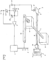
- the pneumatic actuator 1 has a push rod 2 to which a return lever 12 is coupled.
- the return lever 12 is rotatably connected to the tension band 7, on which the lever 8 with the baffle plate 9 and the permanent magnet 10 are attached.
- the permanent magnet 10 is located opposite the air gap of an electromagnet 5 with a coil and an iron circuit, while the baffle plate 9 together with the nozzle 11 forms the nozzle / baffle plate device 6.
- 13 and 14 clamping blocks for the strap 7 are referred to, or the like in practice from parts of a housing. consist.
- the strap 7 is rotatably mounted about its axis.
- the device also includes a pneumatic amplifier 3, a compressed air connection 4, a throttle 21, a medium pressure amplifier 22 with adjustable xp throttle 23 and a pressure regulator 24.
- a magnetic flux proportional to the input variable (the current signal) is generated, which changes the location of the permanent magnet 10 on which the tightening strap 7 acts as a return spring.
- Rotation of the lever 8 about the axis of the tensioning band causes a change in the distance between the baffle plate 9 and the nozzle 11 and a change in the back pressure in the nozzle 11 which is proportional to this is amplified so far that it can be used directly to control the pneumatic actuator 1.
- This in turn generates a mechanical manipulated variable with which a flap, a valve or the like. can be adjusted.
- the control loop is closed via the feedback lever 12, a comparison being made in the tension band 7 between the actual position of the actuator and the position predetermined by the electrical current signal according to the force principle.
- Fig. 2 shows in a detail a possibility for coupling the return lever 12 to the push rod 2.
- a cam 15 is fixed to the push rod 2, while the return lever 12 is rotatably connected to the tension band, one end of which is rotatable about the axis 19 is stored.
- the return lever 12 is biased by the spring 20 against the cam disc 15 and is supported on the latter via the guide roller 16.
- Electromagnet 5, nozzle / baffle device 6 and amplifier 3 are accommodated in a housing to which a compressed air connection 4, an output 17 for a pneumatic signal and an input 18 for a control signal are attached.
- an adjusting screw 23a for the adjustable xp throttle 23 is provided on the housing.
- the up and down movement of the push rod is converted into a pivoting movement of the return lever 12, which causes a torsion of the strap and thus an actual / target comparison based on the force principle.
Landscapes
- Engineering & Computer Science (AREA)
- Physics & Mathematics (AREA)
- General Physics & Mathematics (AREA)
- Automation & Control Theory (AREA)
- Fluid Mechanics (AREA)
- Mechanical Engineering (AREA)
- General Engineering & Computer Science (AREA)
- Supply Devices, Intensifiers, Converters, And Telemotors (AREA)
- Control Of Electric Motors In General (AREA)
- Organic Insulating Materials (AREA)
- Macromonomer-Based Addition Polymer (AREA)
Description
- Die Erfindung bezieht sich auf eine Vorrichtung zur Umwandlung eines elektrischen Stromsignals in eine mechanische Stellgröße, bestehend im wesentlichen aus einem pneumatischen Stellglied mit Schubstange, einem pneumatischen Verstärker, einem Druckluftanschluß und einem elektropneumatischen Signalwandler, der einen Elektromagneten mit Spule, Eisenkreis und Luftspalt, eine Düsen/Prallplatteneinrichtung und einen auf einem Spannband schwenkbar gelagerten Hebel aufweist, der an seinem einen Ende die Prallplatte und an seinem anderen Ende einen gegenüber dem Luftspalt des Elektromagneten angeordneten Permanentmagneten trägt, wobei der Abstand zwischen Prallplatte und Düse proportional zu dem als Eingangssignal durch den Elektromagneten fließenden Strom veränderlich ist und der dementsprechend veränderte Staudruck in der Düse nach pneumatischer Verstärkung direkt zur Ansteuerung des pneumatischen Stellgliedes benutzt wird, und wobei eine Rückführung der mechanischen Stellgröße in den elektropneumatischen Signalwandler vorgesehen ist.
- Für den gleichen Einsatzzweck ist aus der DE-AS 22 64 220 ein elektropneumatischer Signalwandler mit einem elektrischen Meßgerät und einem pneumatischen Nachlaufgerät bekanntgeworden, bei dem die Kopplung des Nachlaufgeräts mit dem Meßgerät über eine Düsen/Prallplatteneinrichtung erfolgt. Die die Düse und die Prallplatte tragenden Steuerglieder sind in Kreuzfedergelenken gelagert, deren Schwenkachsen parallel zueinander in ein und derselben Ebene liegen sollen. Die bekannte Vorrichtung arbeitet nach dem Prinzip des Wegvergleichs. Der Hub des Tauchmagneten wird in eine Bewegung der Prallplatte umgesetzt und die Düse folgt dieser Bewegung durch Nachregeln des Druckes. Ein erheblicher Nachteil dieser Vorrichtung besteht darin, daß die im Düsenbereich realisierbaren Wege von wenigen Zehntelmillimetern verglichen werden müssen mit dem Weg der mechanischen Stellgröße, der im Bereich von 10 bis 100 mm liegt. Dadurch wird ein Hebelverhältnis von 1:100 bis 1:1000 erforderlich, das nur mit sehr langen Hebeln oder mit einer aufwendigen mechanischen Übertragung realisiert werden kann. Dadurch wird das Gerät verhältnismäßig groß und teuer und seine Justage ist sehr schwierig. Hinzukommt, daß bei derartigen Hebelverhältnisses erhebliche Hystersefehler unvermeidbar sind, die weit über dem heute geforderten Wert von 0,5% liegen. Schließlich müssen bei der bekannten Vorrichtung verhältnismäßig große Massen bewegt werden, so daß das Gerät sehr erschütterungsempfindlich ist und deswegen für den direkten Anbau an beispielsweise Prozeßventile kaum in Betracht kommt.
- Aus der EP-A-0 286 722 ist ein elektropneumatischer Stellungsregler bekannt, bei dem das elektrische Eingangssignal über ein Spule-Permamentmagnet-System und die analoge Stellung einer Düse-Prallplatte-Anordnung in einen analogen pneumatischen Druck abgebildet wird und bei dem die Rückkopplung elektrisch über einen pneumatisch-elektrischen Wandler auf das Spule-Magnet-Eingangssystem erfolgt
- In der Schrift DE 32 05 576 C 2 ist eine Vorrichtung zur Umformung elektrischer Signale in pneumatische Signale angegeben, bei dem ebenfalls über ein Elektromagnet-Permanentmagnet-System eine der elektrischen Eingangsgröße analoge Verdrehung einer Prallplatte erzeugt wird, so daß eine entsprechende Druckänderung über einen pneumatischen Verstärker als Ausgangsgröße zur Verfügung steht. Eine dort angegebene Lagerung des Systems Permanentmagnet-Prallplatte sieht als solche ein Spannband vor.
- Der Erfindung lag die Aufgabe zugrunde, eine Vorrichtung der eingangs genannten Art so weiterzubilden, daß die geschilderten Nachteile nicht auftreten können. Insbesondere sollen die bewegten Massen so klein wie möglich gehalten werden, um eine Erschütterungsfestigkeit bis etwa 10g im Frequenzbereich bis 80 Hz und einen Hysteresefehler kleiner 1% erreichen zu können. Angestrebt werden bewegte Massen von weniger als 1 Gramm.
- Zur Lösung dieser Aufgabe wird erfindungsgemäß vorgeschlagen, die gattungsmäßige Vorrichtung so auszubilden, daß ein Ende des Spannbandes um dessen Längsachse drehbar gelagert ist und daß senkrecht zur Längsachse ein Rückführhebel angeordnet ist, dessen eines Ende mit dem drehbaren Ende des Spannbandes drehfest verbunden und dessen freies Ende mit der Schubstange des pneumatischen Stellgliedes gekoppelt ist.
- In weiterer Ausbildung des Erfindungsgedankens ist vorgesehen, daß das freie Ende des Rückführhebels mittels einer Feder gegen eine mit der Schubstange fest verbundene Kurvenscheibe vorgespannt ist und daß das freie Ende des Rückführhebels über eine Führungsrolle auf der Kurvenscheibe abgestützt ist.
- Die erfindungsgemäße Vorrichtung arbeitet nach dem Prinzip des Kraftvergleichs. Die Stellung der Schubstange wird über den Rückführhebel direkt auf die Prallplatte abgebildet, wobei das vorhandene Spannband als elastisch verformbares Element benutzt wird. Über eine entsprechende Auslegung der Federkonstante können große Wege des Stellgliedes in sehr kleine Hübe der Prallplatte umgesetzt werden. Im elektropneumatischen Signalwandler (z.B. gemäß DE-PS 32 05 576) muß nur das Spannband einseitig um seine Achse drehbar gelagert und für die drehfeste Anbinding eines Hebels ausgebildet sein. Es werden keine zusätzlich bewegten Massen benötigt, so daß durch die Rückführung der mechanischen Stellgröße die hervorragenden Eigenschaften des elektropneumatischen Signalwandlers hinsichtlich Erschütterungsunempfindlichkeit und Hysteresefehler nicht beeinträchtigt werden. Da die bewegte Masse weit unter einem Gramm liegt, erreicht man bei 80 Hz ohne weiteres eine Erschütterungsfestigkeit von 5 g und einen Hysteresefehler kleiner 0,5 %.
- Weitere Einzelheiten der Erfindung werden anhand der in den Figuren 1 und 2 dargestellten Ausführungsbeispielen näher erläutert.
- Fig. 1
- zeigt in vereinfachter Darstellung eine Vorrichtung gemäß Anspruch 1,
- Fig. 2
- zeigt Einzelheiten einer Vorrichtung nach den Ansprüchen 2 und 3.
- In Fig .1 ist teils perspektivisch, teils stark vereinfacht eine Vorrichtung gemäß der Erfindung dargestellt. Das pneumatische Stellglied 1 weist eine Schubstange 2 auf, an die ein Rückführhebel 12 angekoppelt ist. Der Rückführhebel 12 ist drehfest mit dem Spannband 7 verbunden, auf dem der Hebel 8 mit der Prallplatte 9 und dem Permanentmagneten 10 angebracht sind. Dabei befindet sich der Permanentmagnet 10 gegenüber dem Luftspalt eines Elektromagneten 5 mit Spule und Eisenkreis, während die Prallplatte 9 zusammen mit der Düse 11 die Düsen/Prallplatteneinrichtung 6 bildet. Mit 13 und 14 sind Einspannblöcke für das Spannband 7 bezeichnet, die in der Praxis aus Teilen eines Gehäuses o.dgl. bestehen. Im vorderen Block 14 ist das Spannband 7 um seine Achse drehbar gelagert. Zu der Vorrichtung gehören ferner ein pneumatischer Verstärker 3, ein Druckluftanschluß 4, eine Drossel 21 ein Mitteldruckverstärker 22 mit einstellbarer xp-Drossel 23 und ein Druckregler 24. Im Elektromagneten 5 wird ein der Eingangsgröße (dem Stromsignal) proportionaler magnetischer Fluß erzeugt, der eine Ortsveränderung des Permanentmagneten 10 bewirkt, auf den das Spannband 7 als Rückstellfeder wirkt. Eine Drehung des Hebels 8 um die Achse des Spannbandes bewirkt eine Veränderung des Abstandes zwischen Prallplatte 9 und Düse 11 und eine damit proportionale Änderung des Staudrucks in der Düse 11. Dadurch wird am Ausgang des Mitteldruckverstärkers 22 ein veränderliches pneumatisches Signal erzeugt, das im Verstärker 3 so weit verstärkt wird, daß es direkt zur Ansteuerung des pneumatischen Stellgliedes 1 benutzt werden kann. Dieses erzeugt seinerseits eine mechanische Stellgröße, mit der eine Klappe, ein Ventil o.dgl. verstellt werden kann. Über den Rückführhebel 12 wird der Regelkreis geschlossen, wobei es im Spannband 7 zu einem Vergleich zwischen der tatsächlichen Position des Stellgliedes mit der durch das elektrische Stromsignal vorgegebenen Position nach dem Kraftprinzip kommt.
- Fig. 2 zeigt im Ausschnitt eine Möglichkeit für die Ankopplung des Rückführhebels 12 an die Schubstange 2. Dabei ist eine Kurvenscheibe 15 fest mit der Schubstange 2 verbunden, während der Rückführhebel 12 drehfest mit dem Spannband verbunden ist, dessen eines Ende um die Achse 19 drehbar gelagert ist. Der Rückführhebel 12 wird durch die Feder 20 gegen die Kurvenscheibe 15 vorgespannt und stützt sich auf dieser über die Führungsrolle 16 ab. Elektromagnet 5, Düsen/Prallplatteneinrichtung 6 und Verstärker 3 sind in einem Gehäuse untergebracht, an dem ein Druckluftanschluß 4, ein Ausgangs 17 für ein pneumatisches Signal und ein Eingang 18 für ein Steuersignal angebracht sind. Außerdem ist am Gehäuse eine Einstellschraube 23a für die einstellbare xp-Drossel 23 vorgesehen. Über die Kurvenscheibe 15 wird die Auf- und Abbewegung der Schubstange in eine Schwenkbewegung des Rückführhebels 12 umgesetzt, die eine Torsion des Spannbandes und damit ein Ist-/Sollvergleich nach dem Kraftprinzip bewirkt.
Claims (3)
- Vorrichtung zur Umwandlung eines elektrischen Stromsignals in eine mechanische Stellgröße, bestehend im wesentlichen aus einem pneumatischen Stellglied (1) mit Schubstange (2), einem pneumatischen Verstärker, einem Druckluftanschluß (4) und einem elektropneumatischen Signalwandler, der einen Elektromagneten (5) mit Spule, Eisenkreis und Luftspalt, eine Düsen/Prallplattenein- richtung (6) und einen auf einem Spannband (7) schwenkbar gelagerten hebel (8) aufweist, der an seinem einen Ende die Prallplatte (9) und an seinem anderen Ende einen gegenüber dem Luftspalt des Elektromagneten (5) angeordneten Permanentmagneten (10) trägt, wobei der Abstand zwischen Prallplatte (9) und Düse (11) proportional zu dem als Eingangssignal durch den Elektromagneten fließenden Strom veränderlich ist und der dementsprechend veränderte Staudruck in der Düse (11) nach pneumatischer Verstärkung direkt zur Ansteuerung des pneumatischen Stellgliedes (1) benutzt wird, und wobei eine Rückführung der mechanischen Stellgröße in den elektropneumatischen Signalwandler vorgesehen ist, dadurch gekennzeichnet, daß ein Ende des Spannbandes (7) um dessen Längsachse drehbar gelagert ist und daß senkrecht zur Längssachse ein Rückführhebel (12) angeordnet ist, dessen eines Ende mit dem drehbaren Ende des Spannbandes (7) drehfest verbunden und dessen freies Ende mit der Schubstange (2) des pneumatischen Stellgliedes gekoppelt ist.
- Vorrichtung nach Anspruch 1, dadurch gekennzeichnet, daß das freie Ende des Rückführhebels (12) mittels einer Feder (20) gegen eine mit der Schubstange (2) fest verbundenen Kurvenscheibe (15) vorgespannt ist.
- Vorrichtung nach Anspruch 1 oder 2, dadurch gekennzeichnet, daß das freie Ende des Rückführhebels (12) über eine Führungsrolle (16) auf der Kurvenscheibe (15) abgestützt ist.
Applications Claiming Priority (2)
| Application Number | Priority Date | Filing Date | Title |
|---|---|---|---|
| DE19914142269 DE4142269A1 (de) | 1991-12-20 | 1991-12-20 | Vorrichtung zur umwandlung eines elektrischen stromsignals in eine mechanische stellgroesse |
| DE4142269 | 1991-12-20 |
Publications (2)
| Publication Number | Publication Date |
|---|---|
| EP0548459A1 EP0548459A1 (de) | 1993-06-30 |
| EP0548459B1 true EP0548459B1 (de) | 1996-09-25 |
Family
ID=6447680
Family Applications (1)
| Application Number | Title | Priority Date | Filing Date |
|---|---|---|---|
| EP19920110917 Expired - Lifetime EP0548459B1 (de) | 1991-12-20 | 1992-06-27 | Vorrichtung zur Umwandlung eines elektrischen Stromsignals in eine mechanische Stellgrösse |
Country Status (5)
| Country | Link |
|---|---|
| US (1) | US5309935A (de) |
| EP (1) | EP0548459B1 (de) |
| AT (1) | ATE143462T1 (de) |
| DE (2) | DE4142269A1 (de) |
| FI (1) | FI925616A7 (de) |
Families Citing this family (3)
| Publication number | Priority date | Publication date | Assignee | Title |
|---|---|---|---|---|
| IT1262508B (it) * | 1993-05-06 | 1996-07-02 | Proel Tecnologie Spa | Dispositivo e metodo per la misura a terra della spinta di propulsori per impiego spaziale. |
| DE4429401C2 (de) * | 1994-08-09 | 1999-01-07 | Hartmann & Braun Gmbh & Co Kg | Druckmittelbetriebener Stellantrieb |
| CN114159156B (zh) * | 2021-12-13 | 2023-09-29 | 成都信息工程大学 | 一种血管介入手术机器人主端触觉交互装置 |
Family Cites Families (12)
| Publication number | Priority date | Publication date | Assignee | Title |
|---|---|---|---|---|
| US2942581A (en) * | 1958-03-12 | 1960-06-28 | Fisher Governor Co | Hydraulic operator |
| US3279490A (en) * | 1963-09-06 | 1966-10-18 | Hitachi Ltd | Apparatus for converting displacement into air pressure |
| US3401603A (en) * | 1967-03-03 | 1968-09-17 | Abex Corp | Fluidic-hydraulic servoactuator |
| DE1601722A1 (de) * | 1967-05-18 | 1970-12-23 | Gulde Regelarmaturen Kg | Pneumatische Stellzylinder mit angebautem Stellungsregler |
| US3503303A (en) * | 1968-04-03 | 1970-03-31 | Itt | Tension spring supporting arrangement |
| DE2264220B2 (de) * | 1972-12-30 | 1976-12-23 | Samson Ag, 6000 Frankfurt | Elektropneumatischer signalwandler |
| FR2440575B1 (fr) * | 1978-10-31 | 1985-12-27 | Samson Ag | Regulateur a effet reactif, en particulier regulateur de position |
| US4329910A (en) * | 1978-12-21 | 1982-05-18 | The Foxboro Company | Transducer assembly providing position output proportional to electrical input signal |
| NO801268L (no) * | 1979-05-04 | 1980-11-05 | Babcock Bristol Ltd | Styreanordning. |
| DE2947627C2 (de) * | 1979-11-27 | 1984-05-24 | Shoketsu Kinzoku Kogyo K.K., Tokyo | Druck- und explosionssichere Stellvorrichtung |
| DE3329944A1 (de) * | 1983-08-19 | 1985-02-28 | Sunvic Regler Gmbh, 5650 Solingen | Pneumatischer stellungsregler |
| DE3712337A1 (de) * | 1987-04-11 | 1988-10-20 | Vdo Schindling | Elektropneumatischer stellungsregler |
-
1991
- 1991-12-20 DE DE19914142269 patent/DE4142269A1/de not_active Withdrawn
-
1992
- 1992-06-27 EP EP19920110917 patent/EP0548459B1/de not_active Expired - Lifetime
- 1992-06-27 AT AT92110917T patent/ATE143462T1/de not_active IP Right Cessation
- 1992-06-27 DE DE59209741T patent/DE59209741D1/de not_active Expired - Fee Related
- 1992-10-13 US US07/959,737 patent/US5309935A/en not_active Expired - Lifetime
- 1992-12-10 FI FI925616A patent/FI925616A7/fi unknown
Also Published As
| Publication number | Publication date |
|---|---|
| DE4142269A1 (de) | 1993-06-24 |
| EP0548459A1 (de) | 1993-06-30 |
| FI925616A7 (fi) | 1993-06-21 |
| ATE143462T1 (de) | 1996-10-15 |
| DE59209741D1 (de) | 1999-10-07 |
| FI925616A0 (fi) | 1992-12-10 |
| US5309935A (en) | 1994-05-10 |
Similar Documents
| Publication | Publication Date | Title |
|---|---|---|
| DE19835491C2 (de) | Niveauregeleinrichtung für Fahrzeuge mit Luftfedern | |
| DE10116479C2 (de) | Verfahren und Regeleinrichtung zur Verstellung einer im Rotorblatt eines Hubschraubers schwenkbar gelagerten Klappe | |
| EP0304610A2 (de) | Regelventileinrichtung | |
| EP0286722B1 (de) | Elektropneumatischer Stellungsregler | |
| DE20018705U1 (de) | Geberarmatur zur Betätigung der Bremse oder der Kupplung eines Fahrzeugs mit Lenker | |
| DE2214750C3 (de) | Kompensationswandler für den Druck eines Druckmittels in ein elektrisches Ausgangssignal | |
| DE3345880C2 (de) | ||
| EP0548459A1 (de) | Vorrichtung zur Umwandlung eines elektrischen Stromsignals in eine mechanische Stellgrösse | |
| DE2810257C2 (de) | Elektropneumatischer Strom/Stellung-Wandler | |
| DE1523498A1 (de) | Verfahrensregler zur gleichzeitigen Regelung mehrerer unterschiedlicher Regelgroessen | |
| EP0439433B1 (de) | Pneumatisches Schieberventil | |
| DE68925200T2 (de) | Magnetostriktives Stellelement mit Selbstanpassender Steuerung | |
| CH694345A5 (de) | Waage mit beweglichem Anschlag. | |
| DE1448778A1 (de) | Pneumatischer Brueckenwandler fuer Drehmomente | |
| DE1295254B (de) | Anordnung zum Steuern der durch eine Leitung mit einem Drosselorgan pro Zeiteinheit fliessenden Menge eines Mediums | |
| DE2619583B2 (de) | Stellmechanismus für einen Funktionsgenerator | |
| DE3326139C2 (de) | ||
| DE2654003C2 (de) | ||
| DE2450700C3 (de) | Pneumatischer Stellungsregler | |
| DE2440228A1 (de) | Messwertumformer | |
| DE2644101C2 (de) | Vorrichtung zur Erfassung einer Meßgröße | |
| EP1111314A1 (de) | Volumenstromregler | |
| DE3049190A1 (de) | Hydraulischer servomechanismus | |
| EP0340478A1 (de) | Pneumatisches Ventil zur Steuerung von Druckluftströmen | |
| DE1473175C (de) | Durchflußmesser mit Differenzdruckmeßwerk |
Legal Events
| Date | Code | Title | Description |
|---|---|---|---|
| PUAI | Public reference made under article 153(3) epc to a published international application that has entered the european phase |
Free format text: ORIGINAL CODE: 0009012 |
|
| AK | Designated contracting states |
Kind code of ref document: A1 Designated state(s): AT DE FR GB IT NL SE |
|
| 18D | Application deemed to be withdrawn |
Effective date: 19931201 |
|
| D18D | Application deemed to be withdrawn (deleted) | ||
| 17P | Request for examination filed |
Effective date: 19950714 |
|
| GRAG | Despatch of communication of intention to grant |
Free format text: ORIGINAL CODE: EPIDOS AGRA |
|
| GRAH | Despatch of communication of intention to grant a patent |
Free format text: ORIGINAL CODE: EPIDOS IGRA |
|
| 17Q | First examination report despatched |
Effective date: 19960229 |
|
| GRAH | Despatch of communication of intention to grant a patent |
Free format text: ORIGINAL CODE: EPIDOS IGRA |
|
| GRAA | (expected) grant |
Free format text: ORIGINAL CODE: 0009210 |
|
| ITF | It: translation for a ep patent filed | ||
| AK | Designated contracting states |
Kind code of ref document: B1 Designated state(s): AT DE FR GB IT NL SE |
|
| REF | Corresponds to: |
Ref document number: 143462 Country of ref document: AT Date of ref document: 19961015 Kind code of ref document: T |
|
| ET | Fr: translation filed | ||
| GBT | Gb: translation of ep patent filed (gb section 77(6)(a)/1977) |
Effective date: 19961101 |
|
| PGFP | Annual fee paid to national office [announced via postgrant information from national office to epo] |
Ref country code: AT Payment date: 19970521 Year of fee payment: 6 |
|
| PGFP | Annual fee paid to national office [announced via postgrant information from national office to epo] |
Ref country code: SE Payment date: 19970523 Year of fee payment: 6 |
|
| PGFP | Annual fee paid to national office [announced via postgrant information from national office to epo] |
Ref country code: NL Payment date: 19970527 Year of fee payment: 6 |
|
| PLBE | No opposition filed within time limit |
Free format text: ORIGINAL CODE: 0009261 |
|
| STAA | Information on the status of an ep patent application or granted ep patent |
Free format text: STATUS: NO OPPOSITION FILED WITHIN TIME LIMIT |
|
| 26N | No opposition filed | ||
| PG25 | Lapsed in a contracting state [announced via postgrant information from national office to epo] |
Ref country code: AT Free format text: LAPSE BECAUSE OF NON-PAYMENT OF DUE FEES Effective date: 19980627 |
|
| PG25 | Lapsed in a contracting state [announced via postgrant information from national office to epo] |
Ref country code: SE Free format text: LAPSE BECAUSE OF NON-PAYMENT OF DUE FEES Effective date: 19980628 |
|
| PG25 | Lapsed in a contracting state [announced via postgrant information from national office to epo] |
Ref country code: NL Free format text: LAPSE BECAUSE OF NON-PAYMENT OF DUE FEES Effective date: 19990101 |
|
| EUG | Se: european patent has lapsed |
Ref document number: 92110917.9 |
|
| NLV4 | Nl: lapsed or anulled due to non-payment of the annual fee |
Effective date: 19990101 |
|
| REG | Reference to a national code |
Ref country code: DE Ref legal event code: 8570 |
|
| REF | Corresponds to: |
Ref document number: 59209741 Country of ref document: DE Date of ref document: 19991007 |
|
| REG | Reference to a national code |
Ref country code: GB Ref legal event code: IF02 |
|
| PGFP | Annual fee paid to national office [announced via postgrant information from national office to epo] |
Ref country code: GB Payment date: 20060615 Year of fee payment: 15 |
|
| PGFP | Annual fee paid to national office [announced via postgrant information from national office to epo] |
Ref country code: FR Payment date: 20060619 Year of fee payment: 15 |
|
| PGFP | Annual fee paid to national office [announced via postgrant information from national office to epo] |
Ref country code: IT Payment date: 20060630 Year of fee payment: 15 |
|
| PGFP | Annual fee paid to national office [announced via postgrant information from national office to epo] |
Ref country code: DE Payment date: 20070622 Year of fee payment: 16 |
|
| GBPC | Gb: european patent ceased through non-payment of renewal fee |
Effective date: 20070627 |
|
| REG | Reference to a national code |
Ref country code: FR Ref legal event code: ST Effective date: 20080229 |
|
| PG25 | Lapsed in a contracting state [announced via postgrant information from national office to epo] |
Ref country code: GB Free format text: LAPSE BECAUSE OF NON-PAYMENT OF DUE FEES Effective date: 20070627 |
|
| PG25 | Lapsed in a contracting state [announced via postgrant information from national office to epo] |
Ref country code: FR Free format text: LAPSE BECAUSE OF NON-PAYMENT OF DUE FEES Effective date: 20070702 |
|
| PG25 | Lapsed in a contracting state [announced via postgrant information from national office to epo] |
Ref country code: DE Free format text: LAPSE BECAUSE OF NON-PAYMENT OF DUE FEES Effective date: 20090101 |
|
| PG25 | Lapsed in a contracting state [announced via postgrant information from national office to epo] |
Ref country code: IT Free format text: LAPSE BECAUSE OF NON-PAYMENT OF DUE FEES Effective date: 20070627 |