EP0546714B1 - Cathode for use in electrolytic cell - Google Patents
Cathode for use in electrolytic cell Download PDFInfo
- Publication number
- EP0546714B1 EP0546714B1 EP92310706A EP92310706A EP0546714B1 EP 0546714 B1 EP0546714 B1 EP 0546714B1 EP 92310706 A EP92310706 A EP 92310706A EP 92310706 A EP92310706 A EP 92310706A EP 0546714 B1 EP0546714 B1 EP 0546714B1
- Authority
- EP
- European Patent Office
- Prior art keywords
- electrode
- nickel
- coating
- metal
- cobalt
- Prior art date
- Legal status (The legal status is an assumption and is not a legal conclusion. Google has not performed a legal analysis and makes no representation as to the accuracy of the status listed.)
- Expired - Lifetime
Links
- PXHVJJICTQNCMI-UHFFFAOYSA-N Nickel Chemical compound [Ni] PXHVJJICTQNCMI-UHFFFAOYSA-N 0.000 claims description 98
- 238000000576 coating method Methods 0.000 claims description 78
- 229910052751 metal Inorganic materials 0.000 claims description 70
- 239000002184 metal Substances 0.000 claims description 70
- 239000011248 coating agent Substances 0.000 claims description 68
- 229910052759 nickel Inorganic materials 0.000 claims description 47
- 239000000758 substrate Substances 0.000 claims description 42
- 229910000765 intermetallic Inorganic materials 0.000 claims description 38
- 238000000034 method Methods 0.000 claims description 35
- XEEYBQQBJWHFJM-UHFFFAOYSA-N Iron Chemical compound [Fe] XEEYBQQBJWHFJM-UHFFFAOYSA-N 0.000 claims description 33
- UFHFLCQGNIYNRP-UHFFFAOYSA-N Hydrogen Chemical compound [H][H] UFHFLCQGNIYNRP-UHFFFAOYSA-N 0.000 claims description 25
- 239000001257 hydrogen Substances 0.000 claims description 25
- 229910052739 hydrogen Inorganic materials 0.000 claims description 25
- 229910052684 Cerium Inorganic materials 0.000 claims description 24
- 229910017052 cobalt Inorganic materials 0.000 claims description 17
- 239000010941 cobalt Substances 0.000 claims description 17
- GUTLYIVDDKVIGB-UHFFFAOYSA-N cobalt atom Chemical compound [Co] GUTLYIVDDKVIGB-UHFFFAOYSA-N 0.000 claims description 17
- 229910052742 iron Inorganic materials 0.000 claims description 17
- 238000007750 plasma spraying Methods 0.000 claims description 16
- 238000010438 heat treatment Methods 0.000 claims description 15
- XKRFYHLGVUSROY-UHFFFAOYSA-N Argon Chemical compound [Ar] XKRFYHLGVUSROY-UHFFFAOYSA-N 0.000 claims description 12
- 229910052747 lanthanoid Inorganic materials 0.000 claims description 12
- 238000005868 electrolysis reaction Methods 0.000 claims description 11
- 239000002245 particle Substances 0.000 claims description 11
- 239000012298 atmosphere Substances 0.000 claims description 10
- 229910000990 Ni alloy Inorganic materials 0.000 claims description 9
- 239000007864 aqueous solution Substances 0.000 claims description 9
- 150000002602 lanthanoids Chemical class 0.000 claims description 9
- 238000011068 loading method Methods 0.000 claims description 9
- 229910000420 cerium oxide Inorganic materials 0.000 claims description 8
- BMMGVYCKOGBVEV-UHFFFAOYSA-N oxo(oxoceriooxy)cerium Chemical compound [Ce]=O.O=[Ce]=O BMMGVYCKOGBVEV-UHFFFAOYSA-N 0.000 claims description 8
- 239000000843 powder Substances 0.000 claims description 8
- 238000002360 preparation method Methods 0.000 claims description 8
- 239000011261 inert gas Substances 0.000 claims description 7
- XLYOFNOQVPJJNP-UHFFFAOYSA-N water Substances O XLYOFNOQVPJJNP-UHFFFAOYSA-N 0.000 claims description 7
- 229910052786 argon Inorganic materials 0.000 claims description 6
- 239000007921 spray Substances 0.000 claims description 6
- 239000012300 argon atmosphere Substances 0.000 claims description 2
- CETPSERCERDGAM-UHFFFAOYSA-N ceric oxide Chemical compound O=[Ce]=O CETPSERCERDGAM-UHFFFAOYSA-N 0.000 claims description 2
- 229910000422 cerium(IV) oxide Inorganic materials 0.000 claims description 2
- 239000011872 intimate mixture Substances 0.000 claims description 2
- ZMIGMASIKSOYAM-UHFFFAOYSA-N cerium Chemical compound [Ce][Ce][Ce][Ce][Ce][Ce][Ce][Ce][Ce][Ce][Ce][Ce][Ce][Ce][Ce][Ce][Ce][Ce][Ce][Ce][Ce][Ce][Ce][Ce][Ce][Ce][Ce][Ce][Ce][Ce][Ce][Ce][Ce][Ce][Ce][Ce][Ce][Ce] ZMIGMASIKSOYAM-UHFFFAOYSA-N 0.000 claims 6
- GWXLDORMOJMVQZ-UHFFFAOYSA-N cerium Chemical compound [Ce] GWXLDORMOJMVQZ-UHFFFAOYSA-N 0.000 description 19
- 239000000203 mixture Substances 0.000 description 19
- BASFCYQUMIYNBI-UHFFFAOYSA-N platinum Chemical group [Pt] BASFCYQUMIYNBI-UHFFFAOYSA-N 0.000 description 12
- -1 aluminium Chemical class 0.000 description 11
- 150000002739 metals Chemical class 0.000 description 11
- WOCIAKWEIIZHES-UHFFFAOYSA-N ruthenium(iv) oxide Chemical compound O=[Ru]=O WOCIAKWEIIZHES-UHFFFAOYSA-N 0.000 description 8
- 239000000463 material Substances 0.000 description 7
- 125000004429 atom Chemical group 0.000 description 6
- 239000000243 solution Substances 0.000 description 6
- XOLBLPGZBRYERU-UHFFFAOYSA-N tin dioxide Chemical compound O=[Sn]=O XOLBLPGZBRYERU-UHFFFAOYSA-N 0.000 description 6
- 229910006069 SO3H Inorganic materials 0.000 description 5
- 230000007797 corrosion Effects 0.000 description 5
- 238000005260 corrosion Methods 0.000 description 5
- 229910044991 metal oxide Inorganic materials 0.000 description 5
- RYGMFSIKBFXOCR-UHFFFAOYSA-N Copper Chemical compound [Cu] RYGMFSIKBFXOCR-UHFFFAOYSA-N 0.000 description 4
- 229910002335 LaNi5 Inorganic materials 0.000 description 4
- KDLHZDBZIXYQEI-UHFFFAOYSA-N Palladium Chemical compound [Pd] KDLHZDBZIXYQEI-UHFFFAOYSA-N 0.000 description 4
- KJTLSVCANCCWHF-UHFFFAOYSA-N Ruthenium Chemical compound [Ru] KJTLSVCANCCWHF-UHFFFAOYSA-N 0.000 description 4
- GWEVSGVZZGPLCZ-UHFFFAOYSA-N Titan oxide Chemical compound O=[Ti]=O GWEVSGVZZGPLCZ-UHFFFAOYSA-N 0.000 description 4
- RTAQQCXQSZGOHL-UHFFFAOYSA-N Titanium Chemical compound [Ti] RTAQQCXQSZGOHL-UHFFFAOYSA-N 0.000 description 4
- 238000002441 X-ray diffraction Methods 0.000 description 4
- 239000003513 alkali Substances 0.000 description 4
- 229910001514 alkali metal chloride Inorganic materials 0.000 description 4
- 229910045601 alloy Inorganic materials 0.000 description 4
- 239000000956 alloy Substances 0.000 description 4
- 230000000052 comparative effect Effects 0.000 description 4
- 229910052802 copper Inorganic materials 0.000 description 4
- 239000010949 copper Substances 0.000 description 4
- 239000012528 membrane Substances 0.000 description 4
- 150000004706 metal oxides Chemical class 0.000 description 4
- 229910052707 ruthenium Inorganic materials 0.000 description 4
- 239000010936 titanium Substances 0.000 description 4
- 229910052719 titanium Inorganic materials 0.000 description 4
- 229910020188 CeNi3 Inorganic materials 0.000 description 3
- HEMHJVSKTPXQMS-UHFFFAOYSA-M Sodium hydroxide Chemical compound [OH-].[Na+] HEMHJVSKTPXQMS-UHFFFAOYSA-M 0.000 description 3
- QCWXUUIWCKQGHC-UHFFFAOYSA-N Zirconium Chemical compound [Zr] QCWXUUIWCKQGHC-UHFFFAOYSA-N 0.000 description 3
- 239000004411 aluminium Substances 0.000 description 3
- 229910052782 aluminium Inorganic materials 0.000 description 3
- XAGFODPZIPBFFR-UHFFFAOYSA-N aluminium Chemical compound [Al] XAGFODPZIPBFFR-UHFFFAOYSA-N 0.000 description 3
- 239000011230 binding agent Substances 0.000 description 3
- 230000000694 effects Effects 0.000 description 3
- 239000003792 electrolyte Substances 0.000 description 3
- 229910052741 iridium Inorganic materials 0.000 description 3
- GKOZUEZYRPOHIO-UHFFFAOYSA-N iridium atom Chemical compound [Ir] GKOZUEZYRPOHIO-UHFFFAOYSA-N 0.000 description 3
- 229910052697 platinum Inorganic materials 0.000 description 3
- 150000003839 salts Chemical class 0.000 description 3
- 125000000020 sulfo group Chemical group O=S(=O)([*])O[H] 0.000 description 3
- 229910052726 zirconium Inorganic materials 0.000 description 3
- 229910020498 Ce2Ni7 Inorganic materials 0.000 description 2
- XTEGARKTQYYJKE-UHFFFAOYSA-M Chlorate Chemical compound [O-]Cl(=O)=O XTEGARKTQYYJKE-UHFFFAOYSA-M 0.000 description 2
- CWYNVVGOOAEACU-UHFFFAOYSA-N Fe2+ Chemical compound [Fe+2] CWYNVVGOOAEACU-UHFFFAOYSA-N 0.000 description 2
- YCKRFDGAMUMZLT-UHFFFAOYSA-N Fluorine atom Chemical compound [F] YCKRFDGAMUMZLT-UHFFFAOYSA-N 0.000 description 2
- 229910001122 Mischmetal Inorganic materials 0.000 description 2
- FAPWRFPIFSIZLT-UHFFFAOYSA-M Sodium chloride Chemical compound [Na+].[Cl-] FAPWRFPIFSIZLT-UHFFFAOYSA-M 0.000 description 2
- 229910000831 Steel Inorganic materials 0.000 description 2
- 239000011149 active material Substances 0.000 description 2
- 238000005422 blasting Methods 0.000 description 2
- 125000003178 carboxy group Chemical group [H]OC(*)=O 0.000 description 2
- 150000001768 cations Chemical class 0.000 description 2
- 230000007423 decrease Effects 0.000 description 2
- 238000000151 deposition Methods 0.000 description 2
- HTXDPTMKBJXEOW-UHFFFAOYSA-N dioxoiridium Chemical compound O=[Ir]=O HTXDPTMKBJXEOW-UHFFFAOYSA-N 0.000 description 2
- 238000005530 etching Methods 0.000 description 2
- 239000011737 fluorine Substances 0.000 description 2
- 229910052731 fluorine Inorganic materials 0.000 description 2
- 229920002313 fluoropolymer Polymers 0.000 description 2
- 239000004811 fluoropolymer Substances 0.000 description 2
- 239000000446 fuel Substances 0.000 description 2
- 238000010348 incorporation Methods 0.000 description 2
- 239000003014 ion exchange membrane Substances 0.000 description 2
- 238000004519 manufacturing process Methods 0.000 description 2
- 229910052762 osmium Inorganic materials 0.000 description 2
- SYQBFIAQOQZEGI-UHFFFAOYSA-N osmium atom Chemical compound [Os] SYQBFIAQOQZEGI-UHFFFAOYSA-N 0.000 description 2
- 229910052763 palladium Inorganic materials 0.000 description 2
- VLTRZXGMWDSKGL-UHFFFAOYSA-N perchloric acid Chemical compound OCl(=O)(=O)=O VLTRZXGMWDSKGL-UHFFFAOYSA-N 0.000 description 2
- 229910052703 rhodium Inorganic materials 0.000 description 2
- 239000010948 rhodium Substances 0.000 description 2
- MHOVAHRLVXNVSD-UHFFFAOYSA-N rhodium atom Chemical compound [Rh] MHOVAHRLVXNVSD-UHFFFAOYSA-N 0.000 description 2
- 239000000523 sample Substances 0.000 description 2
- 238000005507 spraying Methods 0.000 description 2
- 239000010959 steel Substances 0.000 description 2
- 239000000126 substance Substances 0.000 description 2
- 238000012360 testing method Methods 0.000 description 2
- 239000004408 titanium dioxide Substances 0.000 description 2
- ZSLUVFAKFWKJRC-IGMARMGPSA-N 232Th Chemical compound [232Th] ZSLUVFAKFWKJRC-IGMARMGPSA-N 0.000 description 1
- OYPRJOBELJOOCE-UHFFFAOYSA-N Calcium Chemical compound [Ca] OYPRJOBELJOOCE-UHFFFAOYSA-N 0.000 description 1
- 229910000636 Ce alloy Inorganic materials 0.000 description 1
- VEXZGXHMUGYJMC-UHFFFAOYSA-M Chloride anion Chemical compound [Cl-] VEXZGXHMUGYJMC-UHFFFAOYSA-M 0.000 description 1
- VYZAMTAEIAYCRO-UHFFFAOYSA-N Chromium Chemical compound [Cr] VYZAMTAEIAYCRO-UHFFFAOYSA-N 0.000 description 1
- 229920003935 Flemion® Polymers 0.000 description 1
- 229910001209 Low-carbon steel Inorganic materials 0.000 description 1
- 229920000557 Nafion® Polymers 0.000 description 1
- 229910018828 PO3H2 Inorganic materials 0.000 description 1
- KWYUFKZDYYNOTN-UHFFFAOYSA-M Potassium hydroxide Chemical compound [OH-].[K+] KWYUFKZDYYNOTN-UHFFFAOYSA-M 0.000 description 1
- 239000007868 Raney catalyst Substances 0.000 description 1
- 229910000564 Raney nickel Inorganic materials 0.000 description 1
- 229910052776 Thorium Inorganic materials 0.000 description 1
- ATJFFYVFTNAWJD-UHFFFAOYSA-N Tin Chemical compound [Sn] ATJFFYVFTNAWJD-UHFFFAOYSA-N 0.000 description 1
- 239000002253 acid Substances 0.000 description 1
- 239000012190 activator Substances 0.000 description 1
- 239000013543 active substance Substances 0.000 description 1
- 230000002411 adverse Effects 0.000 description 1
- 125000000129 anionic group Chemical group 0.000 description 1
- 125000003118 aryl group Chemical group 0.000 description 1
- 239000002585 base Substances 0.000 description 1
- 239000007767 bonding agent Substances 0.000 description 1
- 229910052791 calcium Inorganic materials 0.000 description 1
- 239000011575 calcium Substances 0.000 description 1
- 125000004432 carbon atom Chemical group C* 0.000 description 1
- 150000001805 chlorine compounds Chemical class 0.000 description 1
- 229910052804 chromium Inorganic materials 0.000 description 1
- 239000011651 chromium Substances 0.000 description 1
- 150000001875 compounds Chemical class 0.000 description 1
- 239000004020 conductor Substances 0.000 description 1
- 230000001419 dependent effect Effects 0.000 description 1
- 230000008021 deposition Effects 0.000 description 1
- 230000006866 deterioration Effects 0.000 description 1
- ZOMNIUBKTOKEHS-UHFFFAOYSA-L dimercury dichloride Chemical class Cl[Hg][Hg]Cl ZOMNIUBKTOKEHS-UHFFFAOYSA-L 0.000 description 1
- 238000007598 dipping method Methods 0.000 description 1
- 239000006185 dispersion Substances 0.000 description 1
- 239000010411 electrocatalyst Substances 0.000 description 1
- 230000005518 electrochemistry Effects 0.000 description 1
- 239000007772 electrode material Substances 0.000 description 1
- NBVXSUQYWXRMNV-UHFFFAOYSA-N fluoromethane Chemical compound FC NBVXSUQYWXRMNV-UHFFFAOYSA-N 0.000 description 1
- 239000012456 homogeneous solution Substances 0.000 description 1
- 238000009533 lab test Methods 0.000 description 1
- 229910052746 lanthanum Inorganic materials 0.000 description 1
- FZLIPJUXYLNCLC-UHFFFAOYSA-N lanthanum atom Chemical compound [La] FZLIPJUXYLNCLC-UHFFFAOYSA-N 0.000 description 1
- 238000002386 leaching Methods 0.000 description 1
- 230000007774 longterm Effects 0.000 description 1
- 229910052748 manganese Inorganic materials 0.000 description 1
- 238000005259 measurement Methods 0.000 description 1
- 125000000896 monocarboxylic acid group Chemical group 0.000 description 1
- 229910000480 nickel oxide Inorganic materials 0.000 description 1
- 229910052758 niobium Inorganic materials 0.000 description 1
- 239000010955 niobium Substances 0.000 description 1
- GUCVJGMIXFAOAE-UHFFFAOYSA-N niobium atom Chemical compound [Nb] GUCVJGMIXFAOAE-UHFFFAOYSA-N 0.000 description 1
- 150000002823 nitrates Chemical class 0.000 description 1
- 229910000510 noble metal Inorganic materials 0.000 description 1
- GNRSAWUEBMWBQH-UHFFFAOYSA-N oxonickel Chemical compound [Ni]=O GNRSAWUEBMWBQH-UHFFFAOYSA-N 0.000 description 1
- HBEQXAKJSGXAIQ-UHFFFAOYSA-N oxopalladium Chemical compound [Pd]=O HBEQXAKJSGXAIQ-UHFFFAOYSA-N 0.000 description 1
- RVTZCBVAJQQJTK-UHFFFAOYSA-N oxygen(2-);zirconium(4+) Chemical compound [O-2].[O-2].[Zr+4] RVTZCBVAJQQJTK-UHFFFAOYSA-N 0.000 description 1
- 229910003445 palladium oxide Inorganic materials 0.000 description 1
- 125000005010 perfluoroalkyl group Chemical group 0.000 description 1
- 239000004033 plastic Substances 0.000 description 1
- 239000010970 precious metal Substances 0.000 description 1
- 230000002035 prolonged effect Effects 0.000 description 1
- 229910052761 rare earth metal Inorganic materials 0.000 description 1
- 150000002910 rare earth metals Chemical class 0.000 description 1
- 238000007788 roughening Methods 0.000 description 1
- 239000011780 sodium chloride Substances 0.000 description 1
- 239000007787 solid Substances 0.000 description 1
- 239000006104 solid solution Substances 0.000 description 1
- 229910052715 tantalum Inorganic materials 0.000 description 1
- GUVRBAGPIYLISA-UHFFFAOYSA-N tantalum atom Chemical compound [Ta] GUVRBAGPIYLISA-UHFFFAOYSA-N 0.000 description 1
- 229910052718 tin Inorganic materials 0.000 description 1
- 239000011135 tin Substances 0.000 description 1
- WFKWXMTUELFFGS-UHFFFAOYSA-N tungsten Chemical compound [W] WFKWXMTUELFFGS-UHFFFAOYSA-N 0.000 description 1
- 229910052721 tungsten Inorganic materials 0.000 description 1
- 239000010937 tungsten Substances 0.000 description 1
- 229910001928 zirconium oxide Inorganic materials 0.000 description 1
Images
Classifications
-
- C—CHEMISTRY; METALLURGY
- C25—ELECTROLYTIC OR ELECTROPHORETIC PROCESSES; APPARATUS THEREFOR
- C25B—ELECTROLYTIC OR ELECTROPHORETIC PROCESSES FOR THE PRODUCTION OF COMPOUNDS OR NON-METALS; APPARATUS THEREFOR
- C25B11/00—Electrodes; Manufacture thereof not otherwise provided for
- C25B11/04—Electrodes; Manufacture thereof not otherwise provided for characterised by the material
- C25B11/051—Electrodes formed of electrocatalysts on a substrate or carrier
- C25B11/073—Electrodes formed of electrocatalysts on a substrate or carrier characterised by the electrocatalyst material
- C25B11/091—Electrodes formed of electrocatalysts on a substrate or carrier characterised by the electrocatalyst material consisting of at least one catalytic element and at least one catalytic compound; consisting of two or more catalytic elements or catalytic compounds
-
- C—CHEMISTRY; METALLURGY
- C25—ELECTROLYTIC OR ELECTROPHORETIC PROCESSES; APPARATUS THEREFOR
- C25B—ELECTROLYTIC OR ELECTROPHORETIC PROCESSES FOR THE PRODUCTION OF COMPOUNDS OR NON-METALS; APPARATUS THEREFOR
- C25B11/00—Electrodes; Manufacture thereof not otherwise provided for
- C25B11/04—Electrodes; Manufacture thereof not otherwise provided for characterised by the material
- C25B11/051—Electrodes formed of electrocatalysts on a substrate or carrier
- C25B11/073—Electrodes formed of electrocatalysts on a substrate or carrier characterised by the electrocatalyst material
Definitions
- This invention relates to a cathode for use in an electrolytic cell, and in particular to a cathode which has a low hydrogen over-voltage when used in the electrolysis of water or aqueous solutions, e.g. aqueous alkali metal chloride solutions.
- the voltage at which a solution may be electrolysed at a given current density is made up of and is influenced by a number of features, namely the theoretical electrolysing voltage, the over-voltages at the anode and cathode, the resistance of the solution which is electrolysed, the resistance of the diaphragm or membrane, if any, positioned between the anode and cathode, and the resistance of the metallic conductors and their contact resistances.
- the hydrogen over-voltage at a cathode may be reduced by increasing the surface area of the cathode, e.g. by etching the surface of the cathode in an acid, or by grit-blasting the surface of the cathode, or by coating the surface of the cathode with mixture of metals, e.g. a mixture of nickel and aluminium, and selectively leaching one of the metals, e.g. aluminium, from the coating.
- mixture of metals e.g. a mixture of nickel and aluminium
- US Patent 4100049 discloses a cathode comprising a substrate of iron, nickel, cobalt or alloys thereof and a coating of a mixture of a precious metal oxide, particularly palladium oxide, and a valve metal oxide particularly zirconium oxide.
- British Patent 1511719 discloses a cathode comprising a metal substrate, which may be ferrous metal, copper or nickel, a coating of cobalt, and a further coating consisting of ruthenium.
- Japanese Patent Publication 54090080 discloses pre-treating an iron cathode with perchloric acid followed by sinter coating the cathode with cathode active substances which may be ruthenium, iridium, iron or nickel in the form of the metal or a compound of the metal.
- Japanese Patent Publication 54110983 discloses a cathode, which may be of mild steel, nickel or nickel alloy, and a coating of a dispersion of nickel or nickel alloy particles and a cathode activator which comprises one or more of platinum, ruthenium, iridium, rhodium, palladium or osmium metal or oxide.
- Japanese Patent Publication 53010036 discloses a cathode having a base of a valve metal and a coating of an alloy of at least one platinum group metal and a valve metal, and optionally a top coating of at least one platinum group metal.
- European Patent 0 129 374 describes a cathode which comprise a metallic substrate and a coating having at least an outer layer of a mixture of at least one platinum group metal and at least one platinum group metal oxide in which the platinum group metal in the mixture with the platinum group metal oxide comprises from 2% to 30% by weight of the mixture.
- the present invention relates to a cathode for use in an electrolytic cell which has a low hydrogen over-voltage when used in the electrolysis of water or aqueous solutions and which does not depend for its effectiveness on the presence of a coating containing a platinum group metal or an oxide thereof, such metals and oxides being relatively expensive.
- APS air plasma spraying at ambient pressure
- a cathode operating at low hydrogen over-voltage for a prolonged period of time at least 12 months, say, may be prepared (hereinafter referred to for convenience as “durable electrode”).
- Such durable electrodes are also resistant to the effects of so-called “cell short-circuit stoppage", that is cell short-circuit stoppage has little adverse effect on the hydrogen over-voltage.
- the first aspect of the present invention provides an electrode suitable for use as a durable low hydrogen over-voltage cathode in an electrolytic cell which electrode comprises a metallic substrate and a coating thereon characterised in that the coating has at least an outer layer which
- cerium oxide provides at least 10% and preferably at least 20% by XRD of the coating.
- the second aspect of the present invention provides a process for the preparation of the electrode according to the first aspect of the present invention which process comprises the Steps of (A) applying an interim coating to the metallic substrate by air plasma spraying an intermetallic compound consisting of cerium. at least one metal selected from the group consisting of iron, cobalt or nickel and optionally up to 2% w/w of a further metal from the lanthanide series; and (B) heating the coated substrate prepared in Step (A) in an inert gas atmosphere.
- the electrode according to the first aspect of the present invention may be prepared by the APS of an intermetallic compound of cerium and at least one non-noble Group 8 metal onto the substrate directly.
- the inert gas used in Step (B) of the process according to the present invention is preferably argon.
- the interim coating produced in Step A of the process according to the present invention typically comprises about 10% by XRD of an intermetallic compound, eg CeNix, wherein x has the meaning hereinafter ascribed to it.
- an intermetallic compound eg CeNix, wherein x has the meaning hereinafter ascribed to it.
- low hydrogen over-voltage electrodes may be prepared by the low pressure plasma-spraying (hereinafter referred to for convenience as "LPPS") of an intermetallic compound of cerium and nickel.
- Coatings prepared by LPPS tend to comprise cerium oxide, non-noble Group 8 metal, preferably Ni, and at least 20Z by XRD of an intermetallic compound of Ce and a non-noble Group 8 metal,eg CeNi x .
- the interim coating comprises cerium oxide, a non-noble Group 8 metal and an oxide thereof and an intermetallic compound of cerium and the non-noble Group 8 metal.
- EP 0,040,097 describes a process for the preparation of electrodes for use in fuel cells or electrolysis cells by depositing a coating of an electrocatalyst on a substrate.
- Deposition is effected by dipping the substrate in or spraying it with a homogeneous solution of salts, eg nitrates and chlorides, of (a) at least one metal selected from Fe, Co, Mn and Ni, (b) at least one metal selected from Mo, Va and W and (c) at least one of certain lanthanide group metals.
- the coated substrates are heated in air and are then cured at an elevated temperature in a reducing atmosphere.
- US 5,021,304 describes an electrode for use as a fuel electrode for solid oxide electrolyte electrochemical cells.
- the electrode described in US 5,021,304 is prepared by a process which comprises the steps of (i) applying to an electrode an admixture consisting essentially of (a) a salt of Ni, Co and mixtures thereof and (b) a salt of Ce, Sr, etc and (ii) heating the admixture in an atmosphere of hydrogen and water.
- Electrode which is a copper or nickel screen to which a mixture of an intermetallic compound LaNi 5 , CeCo 3 , or CeNi 3 and a fluoropolymer is pressed and thermally treated under vacuum.
- the electrode of the present invention does not require the use of a fluoropolymer binder for the intermetallic compound.
- the electrochemical properties of the electrodes of the reference are said to be related to the electrode material as a whole since they will be influenced by the properties of the binder and its proportions.
- cathode for use in a chlor-alkali electrolytic cell in which the cathode comprises a steel or nickel substrate and a plasma-sprayed nickel coating on the substrate.
- a cathode which comprises a hydrogenated species of an AB n material including an AB 5 phase, wherein A is a rare earth metal or calcium, or two or more of these elements, of which up to 0.2 atoms in total may be replaced atom for atom by one or both of zirconium and thorium, and B is nickel or cobalt or both, of which up 1.5 atoms in total may be replaced atom for atom by one or more of copper, aluminium, tin, iron, and chromium, and particles of the AB n material not exceeding 20 ⁇ m in size being bonded by a metallic or electrically conductive plastic binder.
- the cathode of the present invention comprises a metallic substrate.
- the substrate may be of a ferrous metal, or of a film-forming metal, e.g. titanium.
- the substrate of the cathode is made of nickel or a nickel alloy or of another material having an outer face of nickel or nickel alloy.
- the cathode may comprise a core of another metal, e.g. steel or copper, and an outer face of nickel or nickel alloy.
- a substrate comprising nickel or a nickel alloy is preferred on account of the corrosion resistance of such a substrate in an electrolytic cell in which aqueous alkali chloride solution is electrolysed, and on account of the long term low hydrogen over-voltage performance of cathodes of the invention which comprises a substrate of nickel or nickel alloy.
- the substrate of the cathode may have any desired structure.
- it may be in the form of a plate, which may be foraminate, e.g. the cathode may be a perforated plate, or it may be in the form of an expanded metal, or it may be woven or unwoven.
- the cathode is not necessarily in plate form. Thus, it may be in the form of a plurality of so-called cathode fingers between which the anode of the electrolytic cell may be placed.
- the substrate has a high surface area.
- a high surface area may be achieved by roughening the surface of the substrate, for example by chemically etching the surface and/or by grit-blasting the surface.
- the defined coating may be applied directly to the surface of the substrate.
- the defined coating may be applied to an intermediate coating of another material on the surface of the substrate.
- Such an intermediate coating may be, for example, a porous nickel coating.
- the invention will be described hereinafter with reference to a cathode in which such an intermediate coating is not present.
- the intermetallic compound which is to be air-plasma sprayed in the process according to the second aspect of the present invention must contain cerium.
- it may contain one or more other metals of the lanthanide series, e.g. lanthanum itself, that is some of the cerium may be replaced by one or more other lanthanide metals.
- such other metal of the lanthanide series is present in the intermetallic compound it should provide less than 2% w/w of the intermetallic compound and cerium should be present as the major amount of the total metal of the lanthanide series, including cerium.
- the intermetallic compound which is to be air-plasma sprayed contains at least one non-noble Group 8 metal, that is at least one of iron, cobalt and nickel. Intermetallic compounds containing cobalt and/or nickel, particularly nickel, are preferred.
- the intermetallic compound may contain one or more lanthanide metals in additional to cerium and non-noble Group 8 metals but such other metals, if present, will generally be present in a proportion of not more than 2%.
- the intermetallic compound may have an empirical formula CeM x where M is at least one non-noble Group 8 metal, x is in the range of about 1 to 5, and in which some of the cerium may be replaced by one or more other lanthanide metals as hereinbefore described.
- the composition used for plasma spraying may be a neat intermetallic compound, e.g. CeNi 3 , or a mixture of intermetallic compounds, e.g. CeNi 3 and Ce 2 Ni 7 , or an intimate mixture of a metal powder, preferably Ni, with an intermetallic compound, e.g. Ce 2 Ni 7 to form, e.g. notionally CeNi 22 , or a cerium/nickel alloy containing CeNi x phases wherein x is 1-5.
- the concentration of Ce in the intermetallic compound charged to the plasma spray gun is not more than about 50 % w/w and it is often preferred that it is not less than about 10 % w/w.
- amorphous material and/or low levels of a solid solution of cerium in nickel may be present in the coatings.
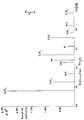
- the present invention is further illustrated by reference to the accompanying drawing.
- the drawing shows an X-ray diffaction pattern of an electrode coating comprising cerium oxide, nickel and nickel oxide.
- the interim coating produced in step A of the process of the present invention essentially comprises oxides of metals and Group 8 metal Typically, up to about 10% by XRD say of intermetallic compound may be present in the interim coatings. The proportion of intermetallic compound in the coating decreases on heating in Steps B as shown by XRD analysis.
- Step B of the process of the present invention depends at least to some extent on the precise method by which the coating is produced as will be discussed hereafter.
- the coated electrode may be produced by direct application of particles of intermetallic compound to the metallic substrate.
- the particles of intermetallic compound may themselves be made by processes known in the art. For example, a mixture of the required metals in the proportions necessary for the production of the intermetallic compound may be melted and the molten mixture may then be comminuted and cooled rapidly to form a plurality of small particles of the intermetallic compound.
- the particles charged to the spray gun typically have a size in the range 0.1 ⁇ m to 250 ⁇ m, although particles having a size outside this range may be used, preferably 20-106 ⁇ and more preferably 45-90 ⁇ m.
- the temperature at which the particles are heated in the plasma-spraying step of process of the second aspect of the present invention may be several thousand °C.
- the power output from the plasma spray gun may be in the range 20 to 55kW.
- the mechanical properties and chemical/physical composition of the coating in the (durable) electrode according to the first aspect of the present invention are dependent on the length of time, the rate of heating and temperature used in Step B. It is preferably heated for less than 8 hours, more preferably above 1 hour.
- the temperature to which it is heated is preferably above 300°C and less than 1000°C and more preferably about 500°C.
- the typical rate of heating is between 1 and 50°C per minute and preferably is in the range 10-20°C/min.
- the proportion of intermetallic compound in the coating decreases on heating in Step B as shown by X-ray diffraction analysis.
- low pressure plasma spraying we mean plasma spraying at low pressure, e.g. about 80-150 mbars, in an inert gas atmosphere, preferably argon.
- the spraying chamber is evacuated and then back-filled with argon to the desired pressure.
- the coating on the surface of the metallic substrate of the electrode of the first aspect of the present invention will be present at a loading of at least 20gm -2 of electrode surface in order that the reduced hydrogen overvoltage provided by the coating should last for a reasonable period of time.
- the length of time for which the reduced hydrogen over-voltage persists is related to the loading of the coating of intermetallic compound and the coating preferably is present at a loading of at least 50gm -2 .
- the coating may be present at a loading of as much as 1200gm -2 or more.
- compositions of the coating of the electrode prepared by the process according to the second aspect of the present invention will depend on inter alia the composition and form, eg size and shape, of the powder and on the plasma spraying conditions used, eg distance of gun from target and gun current.
- the cathode of the invention may be a monopolar electrode or it may form part of a bipolar electrode.
- the cathode is suitable for use in an electrolytic cell comprising an anode, or a plurality of anodes, a cathode, or a plurality of cathodes, and optionally a separator positioned between each adjacent anode and cathode.
- the separator may be a porous electrolyte permeable diaphragm or it may be a hydraulically impermeable cation permselective membrane.
- the anode in the electrolytic cell may be metallic, and the nature of the metal will depend on the nature of the electrolyte to be electrolysed in the electrolytic cell.
- a preferred metal is a film-forming metal, particularly where an aqueous solution of an alkali metal chloride is to be electrolysed in the cell.
- the aforementioned film-forming metal may be one of the metals titanium, zirconium, niobium, tantalum or tungsten or an alloy consisting principally of one or more of these metals and having anodic polarisation properties comparable with those of titanium.
- the anode may have a coating of an electro-conducting electro-catalytically active material.
- this coating may for example consist of one or more platinum group metals, that is platinum, rhodium, iridium, ruthenium, osmium and palladium, or alloys of the said metals, and/or an oxide or oxides thereof.
- the coating may consist of one or more of the platinum group metals and/or oxides thereof in admixture with one or more non-noble metal oxides, particularly a film-forming metal oxide.
- Especially suitable electro-catalytically active coatings include platinum itself and those based on ruthenium dioxide/titanium dioxide, ruthenium dioxide/tin dioxide, ruthenium dioxide/tin dioxide/titanium dioxide, and tin dioxide, ruthenium dioxide and iridium dioxide.
- the membrane is preferably a fluorine-containing polymeric material containing anionic groups.
- the polymeric material is preferably a fluoro-carbon containing the repeating groups. [CF 2 -CF 2 ] m and where m has a value of 2 to 10, and is preferably 2, the ratio of m to n is preferably such as to give an equivalent weight of the groups X in the range 500 to 2000, and X is chosen from A or where p has the value of for example 1 to 3, Z is fluorine or a perfluoroalkyl group having from 1 to 10 carbon atoms, and A is a group chosen from the groups:
- the cathode of the invention is suitable for use in an electrolytic cell in which water or an aqueous solution is electrolysed and in which hydrogen is produced by electrolysis and evolved at the cathode.
- the cathode of the invention finds its greatest application in the electrolysis of aqueous solutions of alkali metal chlorides, particularly aqueous solutions of sodium chloride, and in water electrolysis, e.g. in the electrolysis of aqueous potassium hydroxide solution.
- each cathode comprised a grit-blasted nickel substrate.
- the overvoltage was measured at a current density of 3kAm -2 in a 32% NaOH solution at 90°C and the overvoltage of Grit Blasted Nickel ("GBNi") cathodes was taken as 350mV. It was measured using the average measurements taken from three Luggin probes where the Luggin probes are disposed close (about 1mm) to the electrode surface. A saturated calomel electrode was used as the reference electrode and the voltages obtained from the coated cathodes were compared with that of a GBNi cathode.
- GBNi Grit Blasted Nickel
- short we mean the application of a shorting switch to the cell which allows the applied current to by-pass the cell and allows the cathode to return to its thermodynamic rest potential. This lack of a polarising voltage affords the possibility of corrosion occurring at the cathode coating. It will be appreciated that the ability of the cathode to withstand this change of condition in laboratory experiments is a prime indicator of its potential working durability in commercial chlor-alkali cells.
- the coating loading was determined as weight increase per unit area of cathode.
- Examples 6-17 illustrate durable electrodes according to the present invention (Table 3).
- Examples 1-5 illustrate low over-voltage electrodes prepared by Step A of the process according to the present invention (Table 2).
- a grit-blasted nickel substrate was plasma-sprayed with a powder under essentially the following conditions: Argon flow 40 SLPM Hydrogen flow 10 SLPM Power feed rate 25 g min -1 Current 450A
- Example 18 illustrates a low over-voltage electrode according to the present invention.
- the powder charged to the spray-gun was a cerium/nickel intermetallic compound wherein the weight ratio of cerium:nickel was 50:50.
- Example 5 the cell was on load for 148 days, but not subjected to any shorts.
- Example 6-15, 17 and 20 the electrodes bearing interim coatings prepared under the aforementioned plasma-spraying conditions were subjected to one of the following heat treatments.
- Example 10 which is a Comparative Test in which the electrode was not subjected to any shorts, the cell was on load for 148 days.
- Example 18 illustrates the coating on an electrode prepared by low pressure plasma-spraying a cerium/nickel intermetallic compound (50:50%w/w) without post heat treatment.
- Examples 1-4 demonstrate the low initial over-voltage performance of interim coatings and Example 5 demonstrates that if these interim coatings are not subjected to shorts they will continue performing with very little deterioration.
- Examples 6-9 and comparative example 11 reveal that post-heat treatment in an argon and hydrogen atmosphere respectively increases durability.
- Examples 12-15 reveal that reducing the cerium content of the intermetallic particles charged to the spray-gun to 19 Z w/w has no significant effect on durability on a coated electrode prepared therefrom.
- Examples 1 and 6 reveal that useful electrodes can be obtained at coating loadings down to 50gm -2 .
- Examples 16 and 17 reveal that low cerium content reduces the durability of the coating even after heat treatment.
- Example 20 shows that increasing the NiO content by heating the interim coating in air does not increase durability.
- Example 19 shows that direct plasma spraying of CeO and Ni does not produce a low over-voltage coating.
- Example 20 shows that increasing the proportion of other rare earths (in Misch metal) does not give durable coating.
Landscapes
- Chemical & Material Sciences (AREA)
- Engineering & Computer Science (AREA)
- Chemical Kinetics & Catalysis (AREA)
- Electrochemistry (AREA)
- Materials Engineering (AREA)
- Metallurgy (AREA)
- Organic Chemistry (AREA)
- Electrodes For Compound Or Non-Metal Manufacture (AREA)
- Electrolytic Production Of Non-Metals, Compounds, Apparatuses Therefor (AREA)
- Finishing Walls (AREA)
- Coating By Spraying Or Casting (AREA)
Applications Claiming Priority (4)
| Application Number | Priority Date | Filing Date | Title |
|---|---|---|---|
| GB9126534 | 1991-12-13 | ||
| GB919126536A GB9126536D0 (en) | 1991-12-13 | 1991-12-13 | Cathode for use in electrolytic cell |
| GB919126534A GB9126534D0 (en) | 1991-12-13 | 1991-12-13 | Cathode for use in electrolytic cell |
| GB9126536 | 1991-12-13 |
Publications (2)
| Publication Number | Publication Date |
|---|---|
| EP0546714A1 EP0546714A1 (en) | 1993-06-16 |
| EP0546714B1 true EP0546714B1 (en) | 1999-08-04 |
Family
ID=26300003
Family Applications (1)
| Application Number | Title | Priority Date | Filing Date |
|---|---|---|---|
| EP92310706A Expired - Lifetime EP0546714B1 (en) | 1991-12-13 | 1992-11-23 | Cathode for use in electrolytic cell |
Country Status (15)
| Country | Link |
|---|---|
| US (2) | US5324395A (es) |
| EP (1) | EP0546714B1 (es) |
| JP (1) | JPH06179994A (es) |
| AR (1) | AR247251A1 (es) |
| AU (1) | AU656246B2 (es) |
| CA (1) | CA2084811A1 (es) |
| DE (1) | DE69229711T2 (es) |
| ES (1) | ES2134792T3 (es) |
| FI (1) | FI925636A (es) |
| GB (1) | GB9224595D0 (es) |
| MY (1) | MY108114A (es) |
| NO (1) | NO309988B1 (es) |
| PL (1) | PL169201B1 (es) |
| RU (1) | RU2083724C1 (es) |
| TW (1) | TW243472B (es) |
Cited By (3)
| Publication number | Priority date | Publication date | Assignee | Title |
|---|---|---|---|---|
| US7611796B2 (en) | 2005-09-27 | 2009-11-03 | Ikerlan, S. Coop | Solid-oxide fuel cell with ferritic support |
| US8281780B2 (en) | 2008-12-19 | 2012-10-09 | Coprecitec, S.L. | Regulation valve |
| CN110777320A (zh) * | 2019-10-23 | 2020-02-11 | 福建阿石创新材料股份有限公司 | 一种旋转铌残靶的修复方法 |
Families Citing this family (20)
| Publication number | Priority date | Publication date | Assignee | Title |
|---|---|---|---|---|
| GB9316926D0 (en) * | 1993-08-13 | 1993-09-29 | Ici Plc | Electrode |
| GB9502665D0 (en) * | 1995-02-11 | 1995-03-29 | Ici Plc | Cathode for use in electrolytic cell |
| US5716422A (en) * | 1996-03-25 | 1998-02-10 | Wilson Greatbatch Ltd. | Thermal spray deposited electrode component and method of manufacture |
| US6790554B2 (en) | 1998-10-08 | 2004-09-14 | Imperial Chemical Industries Plc | Fuel cells and fuel cell plates |
| GB9821856D0 (en) * | 1998-10-08 | 1998-12-02 | Ici Plc | Bipolar plates for fuel cells |
| US20040108204A1 (en) | 1999-05-10 | 2004-06-10 | Ineos Chlor Limited | Gasket with curved configuration at peripheral edge |
| US6761808B1 (en) | 1999-05-10 | 2004-07-13 | Ineos Chlor Limited | Electrode structure |
| GB9910714D0 (en) | 1999-05-10 | 1999-07-07 | Ici Plc | Bipolar electrolyser |
| US20050011755A1 (en) * | 2001-08-14 | 2005-01-20 | Vladimir Jovic | Electrolytic cell and electrodes for use in electrochemical processes |
| NO324550B1 (no) | 2001-10-10 | 2007-11-19 | Lasse Kroknes | Anordning ved elektrode, fremgangsmate til fremstilling derav samt anvendelse derav |
| CN101029405B (zh) * | 2006-02-28 | 2010-12-22 | 蓝星(北京)化工机械有限公司 | 活性阴极及其制备方法 |
| DE102006057386A1 (de) * | 2006-12-04 | 2008-06-05 | Uhde Gmbh | Verfahren zum Beschichten von Substraten |
| CN101861412B (zh) * | 2007-11-16 | 2013-04-24 | 阿克佐诺贝尔股份有限公司 | 电极 |
| WO2009086354A1 (en) | 2007-12-27 | 2009-07-09 | 3M Innovative Properties Company | Durable fuel cell membrane electrode assembly with combined additives |
| GB2469265B8 (en) * | 2009-04-06 | 2015-06-17 | Re Hydrogen Ltd | Electrode configuration of electrolysers to protect catalyst from oxidation |
| US7883047B2 (en) | 2009-06-23 | 2011-02-08 | Pai Lung Machinery Mill Co., Ltd. | Tension adjustment structure for fabric winding machine |
| ITMI20091719A1 (it) * | 2009-10-08 | 2011-04-09 | Industrie De Nora Spa | Catodo per processi elettrolitici |
| JP5008043B1 (ja) * | 2011-09-13 | 2012-08-22 | 学校法人同志社 | 塩素発生用陽極 |
| JP6202784B2 (ja) * | 2012-05-18 | 2017-09-27 | 株式会社東芝 | 水素製造装置 |
| RU2553737C2 (ru) * | 2013-03-01 | 2015-06-20 | Федеральное государственное бюджетное образовательное учреждение высшего профессионального образования "Удмуртский государственный университет" (УдГУ) | Катод для электрохимического получения водорода и способ его изготовления |
Family Cites Families (19)
| Publication number | Priority date | Publication date | Assignee | Title |
|---|---|---|---|---|
| US3974058A (en) * | 1974-09-16 | 1976-08-10 | Basf Wyandotte Corporation | Ruthenium coated cathodes |
| US3992278A (en) * | 1975-09-15 | 1976-11-16 | Diamond Shamrock Corporation | Electrolysis cathodes having a melt-sprayed cobalt/zirconium dioxide coating |
| US4024044A (en) * | 1975-09-15 | 1977-05-17 | Diamond Shamrock Corporation | Electrolysis cathodes bearing a melt-sprayed and leached nickel or cobalt coating |
| IL50217A (en) * | 1976-08-06 | 1980-01-31 | Israel State | Electrocatalytically acitve spinel type mixed oxides |
| US4100049A (en) * | 1977-07-11 | 1978-07-11 | Diamond Shamrock Corporation | Coated cathode for electrolysis cells |
| JPS5948872B2 (ja) * | 1978-02-20 | 1984-11-29 | クロリンエンジニアズ株式会社 | 電解用陰極及びその製造法 |
| CA1134903A (en) * | 1979-02-12 | 1982-11-02 | Mary R. Suchanski | Electrode having mixed metal oxide catalysts |
| GB2015032B (en) * | 1979-02-26 | 1982-06-23 | Asahi Glass Co Ltd | Electrodes and processes for preparing them |
| AU541149B2 (en) * | 1979-12-26 | 1984-12-20 | Asahi Kasei Kogyo Kabushiki Kaisha | Hydrogen evolution electrode |
| US4342792A (en) * | 1980-05-13 | 1982-08-03 | The British Petroleum Company Limited | Electrodes and method of preparation thereof for use in electrochemical cells |
| EP0089141B1 (en) * | 1982-03-15 | 1986-12-30 | Inco Alloys International, Inc. | Process for the electrolytic production of hydrogen |
| GB8316778D0 (en) * | 1983-06-21 | 1983-07-27 | Ici Plc | Cathode |
| US4555413A (en) * | 1984-08-01 | 1985-11-26 | Inco Alloys International, Inc. | Process for preparing H2 evolution cathodes |
| US4877508A (en) * | 1985-04-10 | 1989-10-31 | Asahi Glass Company, Ltd. | Highly durable cathode of low hydrogen overvoltage and method for manufacturing the same |
| AU581889B2 (en) * | 1985-04-10 | 1989-03-09 | Asahi Glass Company Limited | Durable low-hydrogen overvoltage cathode |
| US5021304A (en) * | 1989-03-22 | 1991-06-04 | Westinghouse Electric Corp. | Modified cermet fuel electrodes for solid oxide electrochemical cells |
| US5314601A (en) * | 1989-06-30 | 1994-05-24 | Eltech Systems Corporation | Electrodes of improved service life |
| JP2629963B2 (ja) * | 1989-06-30 | 1997-07-16 | 旭硝子株式会社 | 高耐久性低水素過電圧陰極 |
| JPH0375392A (ja) * | 1989-08-18 | 1991-03-29 | Asahi Chem Ind Co Ltd | 水素発生用電極 |
-
1992
- 1992-11-23 ES ES92310706T patent/ES2134792T3/es not_active Expired - Lifetime
- 1992-11-23 EP EP92310706A patent/EP0546714B1/en not_active Expired - Lifetime
- 1992-11-23 GB GB929224595A patent/GB9224595D0/en active Pending
- 1992-11-23 DE DE69229711T patent/DE69229711T2/de not_active Expired - Fee Related
- 1992-11-27 NO NO924602A patent/NO309988B1/no not_active IP Right Cessation
- 1992-11-30 AU AU29711/92A patent/AU656246B2/en not_active Ceased
- 1992-12-08 CA CA002084811A patent/CA2084811A1/en not_active Abandoned
- 1992-12-10 JP JP4330307A patent/JPH06179994A/ja active Pending
- 1992-12-10 AR AR92323865A patent/AR247251A1/es active
- 1992-12-11 PL PL92296974A patent/PL169201B1/pl not_active IP Right Cessation
- 1992-12-11 MY MYPI92002299A patent/MY108114A/en unknown
- 1992-12-11 US US07/987,968 patent/US5324395A/en not_active Expired - Fee Related
- 1992-12-11 FI FI925636A patent/FI925636A/fi unknown
- 1992-12-11 RU RU9292004519A patent/RU2083724C1/ru not_active IP Right Cessation
- 1992-12-16 TW TW081110082A patent/TW243472B/zh active
-
1995
- 1995-04-10 US US08/420,321 patent/US5492732A/en not_active Expired - Fee Related
Cited By (3)
| Publication number | Priority date | Publication date | Assignee | Title |
|---|---|---|---|---|
| US7611796B2 (en) | 2005-09-27 | 2009-11-03 | Ikerlan, S. Coop | Solid-oxide fuel cell with ferritic support |
| US8281780B2 (en) | 2008-12-19 | 2012-10-09 | Coprecitec, S.L. | Regulation valve |
| CN110777320A (zh) * | 2019-10-23 | 2020-02-11 | 福建阿石创新材料股份有限公司 | 一种旋转铌残靶的修复方法 |
Also Published As
| Publication number | Publication date |
|---|---|
| TW243472B (es) | 1995-03-21 |
| FI925636A (fi) | 1993-06-14 |
| NO924602D0 (no) | 1992-11-27 |
| PL296974A1 (en) | 1993-08-23 |
| AU2971192A (en) | 1993-06-17 |
| FI925636A0 (fi) | 1992-12-11 |
| AU656246B2 (en) | 1995-01-27 |
| PL169201B1 (pl) | 1996-06-28 |
| GB9224595D0 (en) | 1993-01-13 |
| ES2134792T3 (es) | 1999-10-16 |
| EP0546714A1 (en) | 1993-06-16 |
| DE69229711D1 (de) | 1999-09-09 |
| MY108114A (en) | 1996-08-15 |
| US5324395A (en) | 1994-06-28 |
| CA2084811A1 (en) | 1993-06-14 |
| NO309988B1 (no) | 2001-04-30 |
| RU2083724C1 (ru) | 1997-07-10 |
| US5492732A (en) | 1996-02-20 |
| AR247251A1 (es) | 1994-11-30 |
| DE69229711T2 (de) | 1999-12-02 |
| JPH06179994A (ja) | 1994-06-28 |
| NO924602L (no) | 1993-06-14 |
Similar Documents
| Publication | Publication Date | Title |
|---|---|---|
| EP0546714B1 (en) | Cathode for use in electrolytic cell | |
| EP3444383B1 (en) | Anode for alkaline water electrolysis and method for producing anode for alkaline water electrolysis | |
| Divisek et al. | Ni and Mo coatings as hydrogen cathodes | |
| Lohrberg et al. | Preparation and use of Raney-Ni activated cathodes for large scale hydrogen production | |
| US5868913A (en) | Electrode and preparation thereof | |
| EP0129374B1 (en) | Cathode for use in electrolytic cell | |
| EP2098616A1 (en) | Cathode for hydrogen generation | |
| JP2006193768A (ja) | 水素発生用陰極 | |
| AU706571B2 (en) | Cathode for use in electrolytic cell | |
| EP0129734B1 (en) | Preparation and use of electrodes | |
| WO2011102431A1 (ja) | 電極基体およびそれを用いた水溶液電気分解用陰極、およびそれらの製造方法 | |
| FI84496B (fi) | Anod foer anvaendning foer framstaellning av vaeteperoxidloesning och foerfarande foer framstaellning av anoden. | |
| EP0226291B1 (en) | Method for extending service life of a hydrogen-evolution electrode | |
| EP0032819B1 (en) | Method of preventing deterioration of palladium oxide anode in a diaphragm type alkali metal chloride electrolytic cell | |
| EP0087185B1 (en) | Manufacture of electrode with lead base | |
| JP2024011284A (ja) | 水素発生電極、及びその製造方法 | |
| Kötz | RuO2/IrO2 electrocatalysts for anodic O2 evolution | |
| EP4204608A1 (en) | Electrode for gas evolution in electrolytic processes | |
| MXPA97005803A (es) | Catodo para utilizarse en una celda electrolitica | |
| Muranaga | Characteristics of Platinum Group Metal Anode for Chlor-Alkali Cells Toshio Muranaga, Yasuhiro Kanaya, and Noriyuki Yokota Daiso Co., Ltd. Otakasu-cho, Amagasaki 660, Japan | |
| CA2048516A1 (en) | Ozone generation |
Legal Events
| Date | Code | Title | Description |
|---|---|---|---|
| PUAI | Public reference made under article 153(3) epc to a published international application that has entered the european phase |
Free format text: ORIGINAL CODE: 0009012 |
|
| AK | Designated contracting states |
Kind code of ref document: A1 Designated state(s): BE DE ES FR GB IT NL SE |
|
| 17P | Request for examination filed |
Effective date: 19931108 |
|
| 17Q | First examination report despatched |
Effective date: 19940922 |
|
| GRAG | Despatch of communication of intention to grant |
Free format text: ORIGINAL CODE: EPIDOS AGRA |
|
| GRAG | Despatch of communication of intention to grant |
Free format text: ORIGINAL CODE: EPIDOS AGRA |
|
| GRAH | Despatch of communication of intention to grant a patent |
Free format text: ORIGINAL CODE: EPIDOS IGRA |
|
| GRAH | Despatch of communication of intention to grant a patent |
Free format text: ORIGINAL CODE: EPIDOS IGRA |
|
| GRAA | (expected) grant |
Free format text: ORIGINAL CODE: 0009210 |
|
| AK | Designated contracting states |
Kind code of ref document: B1 Designated state(s): BE DE ES FR GB IT NL SE |
|
| REF | Corresponds to: |
Ref document number: 69229711 Country of ref document: DE Date of ref document: 19990909 |
|
| ET | Fr: translation filed | ||
| ITF | It: translation for a ep patent filed | ||
| REG | Reference to a national code |
Ref country code: ES Ref legal event code: FG2A Ref document number: 2134792 Country of ref document: ES Kind code of ref document: T3 |
|
| PLBE | No opposition filed within time limit |
Free format text: ORIGINAL CODE: 0009261 |
|
| STAA | Information on the status of an ep patent application or granted ep patent |
Free format text: STATUS: NO OPPOSITION FILED WITHIN TIME LIMIT |
|
| 26N | No opposition filed | ||
| REG | Reference to a national code |
Ref country code: GB Ref legal event code: 732E |
|
| REG | Reference to a national code |
Ref country code: GB Ref legal event code: IF02 |
|
| REG | Reference to a national code |
Ref country code: FR Ref legal event code: TP |
|
| NLS | Nl: assignments of ep-patents |
Owner name: INEOS CHLOR LIMITED |
|
| REG | Reference to a national code |
Ref country code: GB Ref legal event code: 732E |
|
| PGFP | Annual fee paid to national office [announced via postgrant information from national office to epo] |
Ref country code: FR Payment date: 20041010 Year of fee payment: 13 |
|
| PGFP | Annual fee paid to national office [announced via postgrant information from national office to epo] |
Ref country code: GB Payment date: 20041014 Year of fee payment: 13 |
|
| PGFP | Annual fee paid to national office [announced via postgrant information from national office to epo] |
Ref country code: NL Payment date: 20041018 Year of fee payment: 13 |
|
| PGFP | Annual fee paid to national office [announced via postgrant information from national office to epo] |
Ref country code: SE Payment date: 20041020 Year of fee payment: 13 Ref country code: DE Payment date: 20041020 Year of fee payment: 13 |
|
| PGFP | Annual fee paid to national office [announced via postgrant information from national office to epo] |
Ref country code: ES Payment date: 20041104 Year of fee payment: 13 |
|
| PGFP | Annual fee paid to national office [announced via postgrant information from national office to epo] |
Ref country code: BE Payment date: 20041125 Year of fee payment: 13 |
|
| NLS | Nl: assignments of ep-patents |
Owner name: INEOS CHLOR ENTERPRISES LIMITED |
|
| REG | Reference to a national code |
Ref country code: FR Ref legal event code: TP |
|
| PG25 | Lapsed in a contracting state [announced via postgrant information from national office to epo] |
Ref country code: IT Free format text: LAPSE BECAUSE OF NON-PAYMENT OF DUE FEES Effective date: 20051123 Ref country code: GB Free format text: LAPSE BECAUSE OF NON-PAYMENT OF DUE FEES Effective date: 20051123 |
|
| PG25 | Lapsed in a contracting state [announced via postgrant information from national office to epo] |
Ref country code: SE Free format text: LAPSE BECAUSE OF NON-PAYMENT OF DUE FEES Effective date: 20051124 Ref country code: ES Free format text: LAPSE BECAUSE OF NON-PAYMENT OF DUE FEES Effective date: 20051124 |
|
| PG25 | Lapsed in a contracting state [announced via postgrant information from national office to epo] |
Ref country code: BE Free format text: LAPSE BECAUSE OF NON-PAYMENT OF DUE FEES Effective date: 20051130 |
|
| PG25 | Lapsed in a contracting state [announced via postgrant information from national office to epo] |
Ref country code: NL Free format text: LAPSE BECAUSE OF NON-PAYMENT OF DUE FEES Effective date: 20060601 Ref country code: DE Free format text: LAPSE BECAUSE OF NON-PAYMENT OF DUE FEES Effective date: 20060601 |
|
| EUG | Se: european patent has lapsed | ||
| GBPC | Gb: european patent ceased through non-payment of renewal fee |
Effective date: 20051123 |
|
| PG25 | Lapsed in a contracting state [announced via postgrant information from national office to epo] |
Ref country code: FR Free format text: LAPSE BECAUSE OF NON-PAYMENT OF DUE FEES Effective date: 20060731 |
|
| NLV4 | Nl: lapsed or anulled due to non-payment of the annual fee |
Effective date: 20060601 |
|
| REG | Reference to a national code |
Ref country code: FR Ref legal event code: ST Effective date: 20060731 |
|
| REG | Reference to a national code |
Ref country code: ES Ref legal event code: FD2A Effective date: 20051124 |
|
| BERE | Be: lapsed |
Owner name: *INEOS CHLOR ENTERPRISES LTD Effective date: 20051130 |