EP0546239A1 - Méthode de contrôle d'un moteur pour entraîner une pompe hydraulique contrôlant un actuateur hydraulique pour machine de construction - Google Patents
Méthode de contrôle d'un moteur pour entraîner une pompe hydraulique contrôlant un actuateur hydraulique pour machine de construction Download PDFInfo
- Publication number
- EP0546239A1 EP0546239A1 EP92104405A EP92104405A EP0546239A1 EP 0546239 A1 EP0546239 A1 EP 0546239A1 EP 92104405 A EP92104405 A EP 92104405A EP 92104405 A EP92104405 A EP 92104405A EP 0546239 A1 EP0546239 A1 EP 0546239A1
- Authority
- EP
- European Patent Office
- Prior art keywords
- engine
- load
- rpm
- hydraulic
- hydraulic actuator
- Prior art date
- Legal status (The legal status is an assumption and is not a legal conclusion. Google has not performed a legal analysis and makes no representation as to the accuracy of the status listed.)
- Granted
Links
Images


Classifications
-
- F—MECHANICAL ENGINEERING; LIGHTING; HEATING; WEAPONS; BLASTING
- F02—COMBUSTION ENGINES; HOT-GAS OR COMBUSTION-PRODUCT ENGINE PLANTS
- F02D—CONTROLLING COMBUSTION ENGINES
- F02D29/00—Controlling engines, such controlling being peculiar to the devices driven thereby, the devices being other than parts or accessories essential to engine operation, e.g. controlling of engines by signals external thereto
- F02D29/04—Controlling engines, such controlling being peculiar to the devices driven thereby, the devices being other than parts or accessories essential to engine operation, e.g. controlling of engines by signals external thereto peculiar to engines driving pumps
-
- E—FIXED CONSTRUCTIONS
- E02—HYDRAULIC ENGINEERING; FOUNDATIONS; SOIL SHIFTING
- E02F—DREDGING; SOIL-SHIFTING
- E02F9/00—Component parts of dredgers or soil-shifting machines, not restricted to one of the kinds covered by groups E02F3/00 - E02F7/00
- E02F9/20—Drives; Control devices
- E02F9/22—Hydraulic or pneumatic drives
- E02F9/2246—Control of prime movers, e.g. depending on the hydraulic load of work tools
Definitions
- the present invention relates to a method for controlling an engine for driving a hydraulic pump which generates pressurized fluid to drive a hydraulic actuator for a construction equipment and, more particularly, to a method for controlling an engine wherein the number of revolutions (rotational speed) of the engine is controlled in accordance with operating conditions of a hydraulic pump for a hydraulic actuator used in a construction equipment.
- An object of the present invention is to provide a method for controlling an engine for driving a hydraulic pump to supply a pressurized fluid to a hydraulic actuator in a construction equipment without an unnecessary output of the engine and an inappropriate output increase or insufficiency of the engine.
- a method for controlling an engine for driving a hydraulic pump to supply a pressurized fluid to a hydraulic actuator in a construction equipment comprises the steps of:
- the fuel flow is increased to increase the output rotational speed of the engine when the load of the engine for driving the hydraulic pump is more than the first degree after the output rotational speed of the engine is decreased to prevent the excess output of the engine in the engine output decreasing step in the present claimed invention
- the fuel flow is increased according to an actual condition of the load of the engine so that the inappropriate output increase is securely prevented when the fuel flow is kept small to prevent the unnecessary output of the engine and the inappropriate output in sufficiency of the engine is securely prevented when a large output of the engine is needed to operate the actuator.
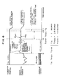
- Fig. 1 shows an actuator driving/controlling apparatus for a construction equipment to which apparatus the present invention is applied. Though there are normally provided a plurality of actuators 1 in the construction equipment, one of them is shown in Fig. 1, as a matter of convenience for clarifying the invention.
- An operation of the actuator 1 is controlled by a high-pressure hydraulic valve 2 which controls a flow rate of high hydraulic pressure output from a high-pressure hydraulic pump 4 to the actuator 1 and/or a flow rate of hydraulic pressure from the actuator 1.
- An operation of the high-pressure hydraulic valve 2 is controlled by low hydraulic pressure which is output from a low-pressure hydraulic pump 5 controlled by a pilot valve 3, the output hydraulic pressure from the low-pressure hydraulic pump 5 is generally in proportion to an inclination angle 0 of an operation lever 6 with respect to its upright position.
- the operation of the actuator 1 is controlled, through the pilot valve 3 and the high-pressure hydraulic valve 2, by the operating lever 6 handled by the operator.
- the actuator 1 is arranged to stop the operation thereof when the inclination angle 0 of the operating lever 6 is zero.
- the high-pressure hydraulic pump 4 and the low-pressure hydraulic pump 5 are driven by an engine 7 including a governer 7 (not shown).
- the number of revolutions (rotational speed) of the engine 7 is adjusted on the basis of a fuel supplying rate which is controlled by a governer lever operation device 8 for moving a governer lever (not shown) of the governer 7.
- the supplying rate of the fuel is regulated in accordance with a position of the governer lever controlled by the governer lever operation device 8.
- the position of the governer lever controlled by the governer lever operation device 8 is determined by a controller 9, depending on the following factors: an output of a revolution number detector 10 for measuring an output revolution number of the engine 7; an output of a pressure gauge 11 which measures the hydraulic pressure applied to the pilot valve 3 in proportion to the operation inclination angle 0 of the operating lever 6 so as to detect a fact that a command for stopping the operation of the actuator 1 is issued or that a command for operating the actuator 1 is issued; an output of an accel setting device 12 for setting a predetermined revolution number of the engine 7 (a revolution number of the engine 7 desirable when the engine rotates without a reduced fuel supplying rate caused by a speed-reduction command according to the invention and with no load, in other words, a revolution number which serves as a reference desired for the engine 7 under the condition with no load, before the fuel supplying rate is decreased or when it is not decreased, in accordance with a condition of the engine load or a state of an actuator operating command); and an output from an AEC setting device for command
- the load of the engine 7 for driving the hydraulic pumps 4 and 5 is measured from a difference between an actual output rotational speed of the engine 7 obtained when the load is measured and an output rotational speed of the engine 7 which is obtainable when the fuel flow supplied to the engine 7 when the load is measured is supplied to the engine 7 when an action of the actuator 1 is stopped.
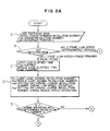
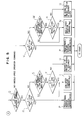
- a ccel 2000 rpm
- a FLOW proceeds from A to B, C and D where the respective values are predetermined in the following manner.
- the FLOW branches to YES at the operating condition judging step E because the engine is desired to rotate with the predetermined revolution number A CCEL .
- the true (Ne > N 11 ) is not achieved because Ne, which is 1800 rpm, is smaller than N 11 , which is 1990 rpm, so that the FLOW branches to NO.
- a light-load elapsed time measuring counter is cleared at the J step and T 11 becomes zero.
- Ne > N 12 is not achieved because Ne, which is 1800 rpm, is smaller than N 12 , which is 1950 rpm, and the FLOW branches to NO.
- a middle-load elapsed time measuring counter at 0 is cleared so that T 12 becomes zero.
- the operation reaches the predetermined rotation operation command step P so as to achieve the desired predetermined operation as indicated by the accel.
- the FLOW returns to START again.
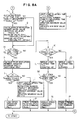
- the engine load condition changes from the heavy-load condition into the light-load condition.
- a no-load neutral condition is supposed as the light load.
- An actual number of the engine revolutions changes from 1800 rpm to 2000 rpm (the revolution number of the engine rotating with no load).
- the FLOW proceeds from A to B, C and D successively. Because the governer lever has been retained at the predetermined position yet, Na is equal to A ccEL which is 2000 rpm at A. Therefore, the values of N 11 , N 12 , N 13 , and N 14 are not changed, respectively, at D and the values in the FLOW (i) are maintained.
- the FLOW branches to YES, similarly to the foregoing FLOW.
- the direction of the FLOW changes at the light-load judging step F. That is to say, since Ne which is 2000 rpm is larger than N 11 which is 1990 rpm, Ne > N 11 is achieved and the FLOW branches to YES.
- a light-load elapsed time measuring counter at G counts up so that T 12 becomes 0.02 seconds if one count corresponds to 0.02 seconds.
- T 11 which is 0.02 seconds is smaller than T 1A which is 3 seconds, and consequently, T 11 > T 1A is not achieved and the FLOW branches to NO.
- a middle-load elapsed time measuring counter at L counts up so that T 12 becomes 0.02 seconds from 0.
- T 12 which is 0.02 seconds is smaller than T 1B which is 10 seconds, and therefore, T 12 > T 1B is not achieved.
- the FLOW reaches P after it branches to NO.
- the predetermined rotation (accel command) operation is still directed and the AEC has not been operated yet.
- This FLOW advances from A to B, c, D, E and up to F, similarly to the FLOW of the paragraph (ii).
- the light-load elapsed time measuring counter G counts up so that T 11 indicates 3.02 seconds.
- T 11 is 3.02 seconds and T 1A is 3 second and T 11 is larger than T 1A , T 11 > T 1A is achieved, and the FLOW branches to YES. As a result, the low-speed operation is commanded for the first time at I. (In addition, the value of the middle-load elapsed time achieved at the last 150th cycle is maintained so that T 12 is 3.00 seconds.)
- the no-load revolution number Na may be calculated through a previously memorized function. It is supposed that the actual engine revolution number Ne under the no-load condition is 1950 rpm. In this way, after Na is renewed, the FLOW proceeds from B to C and D, and the respective values are renewed by the load judging revolution number setting step D as follows.
- the FLOW branches to NO at the operating condition judging step E, and then, the FLOW branches to YES at the adjoining step Q.
- Ne ⁇ N 13 is not achieved and the FLOW branches to NO.
- the FLOW branches to YES because it is measured by the operating condition judging step S that the governer lever is being displaced toward the low speed position thereof.
- the FLOW branches to YES since Ne is 1950 rpm and N 11 is 1940 rpm and Ne is larger than N 11 , Ne ⁇ N 11 , is achieved, the FLOW branches to YES so that the low-speed operation command in which the governer lever is moved to the low speed position gradually is continued at I.
- Ne 1900 rpm.
- Na becomes the low-speed operation revolution number
- the FLOW advances from B to C and D.
- the respective values are renewed at the load judging revolution number setting step D in the following manner.
- the FLOW branches to NO at the operating condition judging step E, and it then branches to YES at the subsequent Q step.
- Ne is 1900 rpm and N 13 is 1830 rpm and Ne is larger than N 13 at the heavy-load judging step R, Ne ⁇ N 13 is not achieved and the FLOW branches to NO.
- the low-speed operation is performed so that the FLOW branches to NO at the operating condition judging step S and directly leads to I. Thus, the low-speed operation is continued under the no-load condition.
- the FLOW is quite similar to the FLOW (v) of the paragraph 1. - 1).
- the respective constants and variables are as follows.
- the FLOW branches to NO at the operating condition judging step E and branches to YES at the subsequent Q step, the FLOW then leading to R.
- Ne is 1750 rpm and N 13 is 1830 rpm and Ne is smaller than N 13 so that the true (Ne ⁇ N 13 ) is achieved.
- the FLOW branches to YES.
- the FLOW gets to P without delay and the predetermined operation is immediately commanded.
- this FLOW becomes similar to the FLOW (i) at the above-mentioned time when the heavy load is supplied.
- the values of both Ne and Na are renewed every time until the governer lever is returned to the position of the predetermined rotation.
- N 11 , N 12 , N 13 and N 14 are also renewed, respectively, in response to the renewal of Na, and the load judging conditions in F and K are renewed.
- the values of the light and middle load elapsed times T 11 and T 12 which have been maintained on the last occasion, are cleared to zero as follows, at the point of time when the FLOW passes J and O for the first time so that when the operation is performed under the light or middle load condition, the counters can start to count up from zero second.
- the FLOW proceeds quite similarly to the above-described FLOW 1.
- the governer lever is also at the intermediate position between the predetermined speed position and the low-speed position. Accordingly, Ne is 1950 rpm and Na is 1950 rpm. The values of Ne and Na at D are also the same.
- the respective values at the input processing unit A are set as follows.
- the FLOW branches to NO at the operating condition judging step E and branches to YES at the subsequent Q step, the FLOW then leading to R.
- Ne is 1920 rpm and N 13 is 1880 rpm and Ne is larger than N 13 so that the true (Ne ⁇ N 13 ) is not achieved. As a result, the FLOW branches to No.
- the FLOW branches to YES because the operation is being changed to the low-speed operation. Further, at the light-load judging step T, because Ne is 1920 rpm and N 11 is 1940 rpm and Ne is smaller than N 11 , Ne > N 11 is not achieved so that the FLOW branches to NO, arriving at the operating condition command step U. As a result, a command for retaining the present position of the governer lever is issued.
- the FLOW becomes similar to the FLOW (iv).
- Ne which is 1950 rpm is larger than N 11 which is 1940 rpm, and accordingly, Ne > N 11 is achieved.
- the operation command changes from the condition retaining command to the low-speed operation command I without delay so that the governer lever is moved to the position of the low-speed operation.
- the light-load judging step T acts to branch the operation command into the following two commands in association with the load judgement at the previous heavy-load judging step R.
- the load condition changes from the heavy-load condition to the middle-load condition.
- About 1970 rpm is selected as a value of the revolution number Ne of the engine rotating with the middle load.
- the number Ne of the engine revolutions changes from 1800 rpm to 1970 rpm.
- the FLOW proceeds from A to B, C and D, successively. Because the governer lever has been retained at the predetermined position yet, Na is equal to A ccEL which is 2000 rpm at A. Therefore, the values of N 11 , N 12 , N 13 and N 14 are not changed, respectively, at D and the values in the FLOW (i) are maintained.
- the FLOW branches to YES, similarly to the foregoing FLOW.
- the FLOW changes at the light-load judging step F. That is to say, since Ne which is 1970 rpm is smaller than N 11 which is 1990 rpm, Ne > N 11 is not achieved and the FLOW branches to NO.
- the last value T 11 is zero, a clearing action is performed.
- a middle-load elapsed time measuring counter at L counts up so that T 12 becomes 0.02 seconds from 0.
- T 12 which is 0.02 seconds is smaller than T 1B which is 10 seconds, and consequently, T 12 > T 1B is achieved.
- the FLOW reaches P after it branches to NO.
- the predetermined rotation (accel command) operation is still directed and the AEC has not been operated yet.
- This FLOW advances from A to B, C, D, E, F, J and up to K, similarly to the aforesaid FLOW (ii).
- the middle-load elapsed time measuring counter at L counts up so that T 12 indicates 10.02 seconds.
- T 12 2 which is 10.02 seconds is larger than T lB which is 10 seconds, T 12 > T lB is achieved, and the FLOW branches to YES.
- the middle-speed operation is commanded for the first time at N.
- the value of the light-load elapsed time is cleared to zero so that T 11 becomes zero second.
- the no-load revolution number Na may be calculated through a previously memorized function. It is supposed that the engine revolution number Ne is 1920 rpm.
- the FLOW branches to NO at the operating condition judging step E and the FLOW also branches to YES at the adjoining step Q.
- New which is 1920 rpm is larger than N 14 which is 1880 rpm, and therefore, Ne ⁇ N 14 is not achieved and the FLOW branches to NO.
- the FLOW branches to YES because it is measured at the operating condition judging step W that the governer lever is being displaced to the middle-speed position.
- Ne > N 11 is achieved, and the FLOW branches to YES so that the middle-speed operation command (te governer lever should be moved to the middle speed position) continues to be issued at N.
- Ne is set to be 1870 rpm.
- Na becomes the revolution number of the engine during the middle-speed operation
- the FLOW advances from B to C and D.
- the respective values are renewed at the load judging revolution number setting step D in the following manner.
- the FLOW branches to NO at the operating condition judging step E and it then branches to NO at the subsequent Q step.
- Ne which is 1870 rpm is larger than N 14 which is 1830 rpm, Ne ⁇ N 14 is not achieved and the FLOW branches to NO.
- the middle-speed operation is performed at the operating condition judging step W so that the FLOW branches to NO and directly leads to N.
- the FLOW branches to NO at the operating condition judging step E and also branches to NO at the subsequent Q step, the FLOW then leading to V.
- Ne of 1750 rpm is smaller than N 14 of 1830 rpm so that the true (Ne ⁇ N 14 ) is achieved. As a result, the FLOW branches to YES.
- the FLOW gets to P without delay and the predetermined operation is immediately commanded.
- this FLOW becomes similar to the above-described FLOW (i) during charging the heavy load.
- the values of both Ne and Na are renewed every time until the governer lever is returned to the position of the predetermined rotation.
- the values of N 11 , N 12 , N 13 and N 14 are also renewed, respectively.
- the load judging conditions of F and K are renewed.
- the values of the light and middle load elapsed times T 11 and T 12 which have been maintained on the last occasion, are cleared to zero as follows, at the point of time when the FLOW passes J and O for the first time.
- the counters can start to count up from zero second.
- the FLOW proceeds quite similarly to the above-described FLOW 2.
- the governer lever is also at the intermediate position between the predetermined speed position and the low-speed position. Accordingly, Ne is 1920 rpm and Na is 1950 rpm. The values of Ne and Na at D are also the same.
- the FLOW advances from B to C and D.
- the values of the last FLOW (iv) are maintained at D.
- the FLOW branches to NO at the operating condition judging step E and branches to NO at the subsequent Q step, the FLOW then leading to V.
- Ne of 1890 rpm is larger than N 14 of 1880 rpm so that the true (Ne ⁇ N 14 ) is not achieved.
- the FLOW branches YES because the engine operates during transition to the middle-speed operation. Further, at the middle-load judging step X, because Ne of 1890 rpm is smaller than N 12 of 1900 rpm, Ne > N 12 is not achieved. As a result, the FLOW branches to NO, arriving at the operating condition commanding step U where the command to retain the present position of the governer lever is issued.
- the FLOW becomes similar to the FLOW (iv) at that point of time.
- Ne of 1920 rpm is larger than N 12 of 1900 rpm, and accordingly, Ne > N 11 is achieved.
- the operation command changes from the condition retaining command to the middle-speed operation command N without delay so that the governer lever is moved to the position of the middle-speed operation again.
- the middle-load judging step X acts to branch the operation command into the following two commands in association with the load judgement at the previous heavy-load judging step V.
- the present position of the governer lever is retained without reducing the revolution number to that of the middle-speed operation.
- a supplying rate of the fuel is changed by displacing the position of the governer lever.
- the fuel supplying rate is changed in accordance with the load even in case of retaining the position of the governer lever. In this case, therefore, the governer lever may be operated so that the fuel supplying rate at that time may be maintained without retaining the present position of the governer lever.
- the number of revolutions of the engine varies in accordance with the variation of the load.
- the engine revolution number is stably set at a certain value, exclusive of an overshoot output period immediately after beginning of the load is eliminated. Succeedingly, measurement of the variation amount of the engine revolution number can be one condition for judging the no-load condition.
- This FLOW is quite similar to the FLOWs described above. However, at the signal input processing step A, the pressure switch signal ON (during charging the load) or OFF (with no load) is input. Since the operation is performed under the heavy-load condition, ON is detected at the pressure switch signal judging step a so that the FLOW bypasses b to branch to F, differently from the aforesaid FLOWs.
- the engine revolution number Ne varies while the pressure switch signal changes from ON to OFF.
- the FLOW advances from B to C, D, E and a, and it then branches to YES at the a step since the pressure switch signal is OFF.
- Ne > N 11 is kept by the rewriting of N 11 and the FLOW branches to YES.
- a counter counts up such that T 12 is 0.02 seconds, whereas T 12 of 0.02 second is smaller than T 1B which is 10 seconds at M so that the true (T 12 > T 1B ) is not achieved. Therefore, the predetermined rotation command is still maintained at P.
- the FLOW proceeds from A to B, C, D, E, a, b, F and G.
- T 11 and T 13 both become 1.8 seconds.
- the FLOW branches to YES at the revolution number stable measurement start time judging step c.
- the measurement reference revolution number N 1STD is predetermined to be 2000 rpm which is equal to Ne.
- the FLOW branches to H because T 13 > T 1STRT is not achieved, and it subsequently advances from H to K, L, M and P, thereby maintaining the predetermined rotation command.
- the FLOW advances from A to V, c, D, e, a, b, F, G, c and d successively.
- the FLOW branches to NO becasue T 13 of 2.4 seconds is not equal to T 1STRT of 1.8 seconds (in other words, the measurement reference revolution number is not renewed and N 1STD of 2000 rpm is maintained), then branching to f.
- T 13 is smaller than T IFNSH which is 2.8 seconds and larger than T 1STRT which is 1.8 seconds, the FLOW branches to g for calculating the varied values of the revolution number.
- a state obtained before a light-load tolerance time has not elapsed after the revolution number stable measurement time was elapsed will be described.
- the FLOW advances from A to B, C, D, E, a, b, F, G, c, d and f, where it branches to H and the revolution number variation is not calculated.
- H because it is before the light-load tolerance elapsed time (T 1A ), the FLOW branches to K, L, M and P.
- the engine keeps to rotate at the predetermined speed.
- the elapsed time T 11 is equal to T 13 which is 3.02 seconds.
- the FLOW proceeds from A to B, C, D, E, a, b, F, G, c, d, f and H.
- the FLOW branches to YES, then arriving at h.
- the maximum and minimum varied values (M A ⁇ 1 , M 1NI ) which have been sorted in the previous revolution number varied value arithmetic step are used to calculate a revolution number varied maximum range N ⁇ FF.
- N DIFF ⁇ N STAB In the case where N DIFF ⁇ N STAB is not achieved, it is considered that the load is charged.
- this FLOW advances from A to B, C, D, E, Q, R and P. More particularly, when any load is charged, irrespective of the largeness of the load, during the low-speed operation with no load (that is, just when the pressure switch becomes ON), the low-speed operation returns to the predetermined rotation operation unconditionally.
- the supplying rate of the fuel to the engine is increased to raise the engine revolution number. It is also possible to measure the engine load from an actual output torque of the engine which is obtained from a torque sensor provided on an output shaft of the engine. It is further possible to measure the engine load from a hydraulic pump output flow rate to be output from a flow rate sensor provided on a pipe for feeding pressurized fluid to the actuators.
Landscapes
- Engineering & Computer Science (AREA)
- General Engineering & Computer Science (AREA)
- Chemical & Material Sciences (AREA)
- Combustion & Propulsion (AREA)
- Mechanical Engineering (AREA)
- Mining & Mineral Resources (AREA)
- Civil Engineering (AREA)
- Structural Engineering (AREA)
- Control Of Vehicle Engines Or Engines For Specific Uses (AREA)
- Operation Control Of Excavators (AREA)
- Electrical Control Of Air Or Fuel Supplied To Internal-Combustion Engine (AREA)
Applications Claiming Priority (2)
| Application Number | Priority Date | Filing Date | Title |
|---|---|---|---|
| JP297393/91 | 1991-11-13 | ||
| JP29739391 | 1991-11-13 |
Publications (2)
| Publication Number | Publication Date |
|---|---|
| EP0546239A1 true EP0546239A1 (fr) | 1993-06-16 |
| EP0546239B1 EP0546239B1 (fr) | 1997-04-16 |
Family
ID=17845914
Family Applications (1)
| Application Number | Title | Priority Date | Filing Date |
|---|---|---|---|
| EP92104405A Expired - Lifetime EP0546239B1 (fr) | 1991-11-13 | 1992-03-13 | Méthode de contrÔle d'un moteur pour entraîner une pompe hydraulique contrÔlant un actuateur hydraulique pour machine de construction |
Country Status (5)
| Country | Link |
|---|---|
| US (1) | US5286171A (fr) |
| EP (1) | EP0546239B1 (fr) |
| AU (1) | AU637283B1 (fr) |
| CA (1) | CA2062591C (fr) |
| DE (1) | DE69219080T2 (fr) |
Cited By (3)
| Publication number | Priority date | Publication date | Assignee | Title |
|---|---|---|---|---|
| EP0774546A1 (fr) * | 1995-11-23 | 1997-05-21 | Samsung Heavy Industries Co., Ltd | Dispositif pour régler la vitesse de rotation du moteur d'un engin de terras- sement hydraulique. |
| EP0884421A2 (fr) * | 1997-06-10 | 1998-12-16 | Hitachi Construction Machinery Co., Ltd. | Système de commande du moteur d'une machine de chantier |
| GB2616459A (en) * | 2022-03-10 | 2023-09-13 | Caterpillar Inc | Controller, system, and method for controlling engine of machine |
Families Citing this family (8)
| Publication number | Priority date | Publication date | Assignee | Title |
|---|---|---|---|---|
| CA2213457C (fr) * | 1995-03-14 | 2005-05-24 | The Boeing Company | Systeme de commande de pompe hydraulique pour avion |
| KR100257852B1 (ko) * | 1995-10-31 | 2000-06-01 | 토니헬샴 | 유압식 건설기계의 엔진회전수 제어방법 |
| US6029448A (en) * | 1997-12-08 | 2000-02-29 | Fenner Fluid Power | Low noise hydraulic power unit for an auto-hoist lift |
| US7255539B1 (en) * | 2002-05-09 | 2007-08-14 | Clarke Fire Protection Products | Pump pressure limiting engine speed control |
| US20090129935A1 (en) * | 2007-11-21 | 2009-05-21 | Kunkler Kevin J | Pump suction pressure limiting speed control and related pump driver and sprinkler system |
| US20110072811A1 (en) * | 2009-09-30 | 2011-03-31 | Rs Drawings, Llc | Engine driven lift gate power system |
| JP5222975B2 (ja) * | 2011-05-18 | 2013-06-26 | 株式会社小松製作所 | 作業機械のエンジン制御装置およびそのエンジン制御方法 |
| WO2012170394A1 (fr) | 2011-06-09 | 2012-12-13 | Clarke Fire Protection Products, Inc. | Agencements de refroidissement pour des pompes à incendie d'un système d'extincteurs à des fins d'extinction d'incendie |
Citations (6)
| Publication number | Priority date | Publication date | Assignee | Title |
|---|---|---|---|---|
| EP0073288A1 (fr) * | 1981-08-28 | 1983-03-09 | H. Weyhausen KG Maschinenfabrik | Dispositif pour régler automatiquement la vitesse de rotation d'un moteur d'excavatrice |
| US4549400A (en) * | 1982-04-19 | 1985-10-29 | King Alex C | Electro-hydraulic engine throttle control |
| EP0166546A1 (fr) * | 1984-05-31 | 1986-01-02 | Kabushiki Kaisha Komatsu Seisakusho | Appareil de contrôle de la vitesse de rotation d'un moteur monté sur un engin de terrassement |
| GB2184162A (en) * | 1985-12-17 | 1987-06-17 | Komatsu Mfg Co Ltd | Apparatus for controlling the speed of an engine |
| EP0287670A1 (fr) * | 1986-10-05 | 1988-10-26 | Hitachi Construction Machinery Co., Ltd. | Dispositif de commande d'entrainement pour machines de construction hydrauliques |
| FR2645592A1 (fr) * | 1989-04-10 | 1990-10-12 | Linde Ag | Procede pour le fonctionnement d'une unite motrice, excavateur ou analogues |
Family Cites Families (7)
| Publication number | Priority date | Publication date | Assignee | Title |
|---|---|---|---|---|
| SE394903B (sv) * | 1974-01-23 | 1977-07-18 | Akermans Verkstad Ab | Anordning for varvtalsreglering av en motor, serskilt dieselmotor i en arbetsmaskin |
| US4534707A (en) * | 1984-05-14 | 1985-08-13 | Caterpillar Tractor Co. | Hydrostatic vehicle control |
| US4588357A (en) * | 1984-07-24 | 1986-05-13 | Power Draulics-Nielsen, Inc. | Hydraulic throttle control |
| JPS60234101A (ja) * | 1985-03-25 | 1985-11-20 | Hitachi Constr Mach Co Ltd | 油圧式建設機械の油圧系統の制御方法 |
| EP0457365B1 (fr) * | 1986-08-15 | 1994-10-19 | Kabushiki Kaisha Komatsu Seisakusho | Appareil pour le contrôle d'une pompe hydraulique |
| US5155996A (en) * | 1989-01-18 | 1992-10-20 | Hitachi Construction Machinery Co., Ltd. | Hydraulic drive system for construction machine |
| JP2798411B2 (ja) * | 1989-02-28 | 1998-09-17 | 東芝機械株式会社 | ポンプの吐出流量制御装置 |
-
1992
- 1992-03-10 CA CA002062591A patent/CA2062591C/fr not_active Expired - Lifetime
- 1992-03-10 US US07/848,176 patent/US5286171A/en not_active Expired - Lifetime
- 1992-03-13 EP EP92104405A patent/EP0546239B1/fr not_active Expired - Lifetime
- 1992-03-13 DE DE69219080T patent/DE69219080T2/de not_active Expired - Lifetime
- 1992-04-06 AU AU14093/92A patent/AU637283B1/en not_active Ceased
Patent Citations (6)
| Publication number | Priority date | Publication date | Assignee | Title |
|---|---|---|---|---|
| EP0073288A1 (fr) * | 1981-08-28 | 1983-03-09 | H. Weyhausen KG Maschinenfabrik | Dispositif pour régler automatiquement la vitesse de rotation d'un moteur d'excavatrice |
| US4549400A (en) * | 1982-04-19 | 1985-10-29 | King Alex C | Electro-hydraulic engine throttle control |
| EP0166546A1 (fr) * | 1984-05-31 | 1986-01-02 | Kabushiki Kaisha Komatsu Seisakusho | Appareil de contrôle de la vitesse de rotation d'un moteur monté sur un engin de terrassement |
| GB2184162A (en) * | 1985-12-17 | 1987-06-17 | Komatsu Mfg Co Ltd | Apparatus for controlling the speed of an engine |
| EP0287670A1 (fr) * | 1986-10-05 | 1988-10-26 | Hitachi Construction Machinery Co., Ltd. | Dispositif de commande d'entrainement pour machines de construction hydrauliques |
| FR2645592A1 (fr) * | 1989-04-10 | 1990-10-12 | Linde Ag | Procede pour le fonctionnement d'une unite motrice, excavateur ou analogues |
Non-Patent Citations (1)
| Title |
|---|
| PATENT ABSTRACTS OF JAPAN vol. 014, no. 540 (M-1053)29 November 1990 & JP-A-02 227 571 ( TOSHIBA MACH CO LTD ) 10 September 1990 * |
Cited By (4)
| Publication number | Priority date | Publication date | Assignee | Title |
|---|---|---|---|---|
| EP0774546A1 (fr) * | 1995-11-23 | 1997-05-21 | Samsung Heavy Industries Co., Ltd | Dispositif pour régler la vitesse de rotation du moteur d'un engin de terras- sement hydraulique. |
| EP0884421A2 (fr) * | 1997-06-10 | 1998-12-16 | Hitachi Construction Machinery Co., Ltd. | Système de commande du moteur d'une machine de chantier |
| EP0884421A3 (fr) * | 1997-06-10 | 1999-07-21 | Hitachi Construction Machinery Co., Ltd. | Système de commande du moteur d'une machine de chantier |
| GB2616459A (en) * | 2022-03-10 | 2023-09-13 | Caterpillar Inc | Controller, system, and method for controlling engine of machine |
Also Published As
| Publication number | Publication date |
|---|---|
| US5286171A (en) | 1994-02-15 |
| EP0546239B1 (fr) | 1997-04-16 |
| CA2062591A1 (fr) | 1993-05-14 |
| DE69219080T2 (de) | 1997-09-11 |
| AU637283B1 (en) | 1993-05-20 |
| CA2062591C (fr) | 1999-05-11 |
| DE69219080D1 (de) | 1997-05-22 |
Similar Documents
| Publication | Publication Date | Title |
|---|---|---|
| EP0546239A1 (fr) | Méthode de contrôle d'un moteur pour entraîner une pompe hydraulique contrôlant un actuateur hydraulique pour machine de construction | |
| EP0928849B1 (fr) | Système avertisseur de défaillances des pompes dans les machines de chantier | |
| EP0844338B1 (fr) | Dispositif de commande pour un moteur hydraulique | |
| US6173573B1 (en) | Control device for hydraulic drive machine | |
| US5527156A (en) | Apparatus for and method of controlling engine and pumps of hydraulic construction equipment | |
| EP0587902B1 (fr) | Systeme de commande hydraulique | |
| US6182448B1 (en) | Speed changing device for hydraulic driving apparatus and speed change control method thereof | |
| EP0504415B1 (fr) | Systeme de commande pour pompe hydraulique | |
| JP4136041B2 (ja) | 油圧作業機の油圧駆動装置 | |
| KR20010022791A (ko) | 작업기의 제어방법 및 그 제어장치 | |
| US5435131A (en) | Adaptive overspeed control for a hydrostatic transmission | |
| EP0344311B1 (fr) | Appareil hydraulique pour machines utilisees dans la construction | |
| CN1070564C (zh) | 控制液压建筑机械中的发动机转速的方法 | |
| EP0493596B1 (fr) | Circuit de regulation de capacite pour pompe a capacite variable | |
| EP0551513A1 (fr) | Systeme hydraulique de commande d'engin de chantier | |
| KR100256897B1 (ko) | 유압작업기의엔진회전수의제어장치 | |
| KR100433186B1 (ko) | 굴삭기의 엔진과 펌프의 출력 자동 제어 시스템 | |
| JPH09273183A (ja) | 油圧式建設機械のエンジン回転数制御装置 | |
| JP2920057B2 (ja) | 建設機械の油圧制御装置 | |
| EP0632167A2 (fr) | Dispositif et procédé par la commande d'engins de chantier hydrauliques | |
| JP2981339B2 (ja) | 建設機械用アクチュエーター油圧源ポンプ駆動エンジンの制御方法 | |
| JPH04143428A (ja) | 建設機械の制御装置 | |
| JP2872558B2 (ja) | 建設機械の油圧制御装置 | |
| JPH0510269A (ja) | 可変容量型油圧ポンプの吸収トルク制御方法 | |
| KR100240080B1 (ko) | 중장비의 출력제어장치 |
Legal Events
| Date | Code | Title | Description |
|---|---|---|---|
| PUAI | Public reference made under article 153(3) epc to a published international application that has entered the european phase |
Free format text: ORIGINAL CODE: 0009012 |
|
| AK | Designated contracting states |
Kind code of ref document: A1 Designated state(s): BE DE FR GB |
|
| 17P | Request for examination filed |
Effective date: 19930713 |
|
| 17Q | First examination report despatched |
Effective date: 19941028 |
|
| GRAG | Despatch of communication of intention to grant |
Free format text: ORIGINAL CODE: EPIDOS AGRA |
|
| GRAH | Despatch of communication of intention to grant a patent |
Free format text: ORIGINAL CODE: EPIDOS IGRA |
|
| GRAH | Despatch of communication of intention to grant a patent |
Free format text: ORIGINAL CODE: EPIDOS IGRA |
|
| GRAA | (expected) grant |
Free format text: ORIGINAL CODE: 0009210 |
|
| AK | Designated contracting states |
Kind code of ref document: B1 Designated state(s): BE DE FR GB |
|
| REF | Corresponds to: |
Ref document number: 69219080 Country of ref document: DE Date of ref document: 19970522 |
|
| ET | Fr: translation filed | ||
| PLBE | No opposition filed within time limit |
Free format text: ORIGINAL CODE: 0009261 |
|
| STAA | Information on the status of an ep patent application or granted ep patent |
Free format text: STATUS: NO OPPOSITION FILED WITHIN TIME LIMIT |
|
| 26N | No opposition filed | ||
| REG | Reference to a national code |
Ref country code: GB Ref legal event code: IF02 |
|
| REG | Reference to a national code |
Ref country code: FR Ref legal event code: CD |
|
| PGFP | Annual fee paid to national office [announced via postgrant information from national office to epo] |
Ref country code: FR Payment date: 20100324 Year of fee payment: 19 |
|
| PGFP | Annual fee paid to national office [announced via postgrant information from national office to epo] |
Ref country code: GB Payment date: 20100310 Year of fee payment: 19 Ref country code: BE Payment date: 20100215 Year of fee payment: 19 |
|
| REG | Reference to a national code |
Ref country code: FR Ref legal event code: TP |
|
| PGFP | Annual fee paid to national office [announced via postgrant information from national office to epo] |
Ref country code: DE Payment date: 20100415 Year of fee payment: 19 |
|
| BERE | Be: lapsed |
Owner name: CATERPILLAR SARL Effective date: 20110331 |
|
| GBPC | Gb: european patent ceased through non-payment of renewal fee |
Effective date: 20110313 |
|
| REG | Reference to a national code |
Ref country code: FR Ref legal event code: ST Effective date: 20111130 |
|
| PG25 | Lapsed in a contracting state [announced via postgrant information from national office to epo] |
Ref country code: BE Free format text: LAPSE BECAUSE OF NON-PAYMENT OF DUE FEES Effective date: 20110331 |
|
| PG25 | Lapsed in a contracting state [announced via postgrant information from national office to epo] |
Ref country code: FR Free format text: LAPSE BECAUSE OF NON-PAYMENT OF DUE FEES Effective date: 20110331 Ref country code: DE Free format text: LAPSE BECAUSE OF NON-PAYMENT OF DUE FEES Effective date: 20111001 |
|
| REG | Reference to a national code |
Ref country code: DE Ref legal event code: R119 Ref document number: 69219080 Country of ref document: DE Effective date: 20111001 |
|
| PG25 | Lapsed in a contracting state [announced via postgrant information from national office to epo] |
Ref country code: GB Free format text: LAPSE BECAUSE OF NON-PAYMENT OF DUE FEES Effective date: 20110313 |