US5527156A - Apparatus for and method of controlling engine and pumps of hydraulic construction equipment - Google Patents
Apparatus for and method of controlling engine and pumps of hydraulic construction equipment Download PDFInfo
- Publication number
- US5527156A US5527156A US08/334,217 US33421794A US5527156A US 5527156 A US5527156 A US 5527156A US 33421794 A US33421794 A US 33421794A US 5527156 A US5527156 A US 5527156A
- Authority
- US
- United States
- Prior art keywords
- oil quantity
- pump
- signal
- pump delivery
- engine
- Prior art date
- Legal status (The legal status is an assumption and is not a legal conclusion. Google has not performed a legal analysis and makes no representation as to the accuracy of the status listed.)
- Expired - Fee Related
Links
- 238000000034 method Methods 0.000 title claims abstract description 17
- 238000010276 construction Methods 0.000 title claims abstract description 14
- 238000001514 detection method Methods 0.000 claims abstract description 30
- 238000006073 displacement reaction Methods 0.000 claims description 6
- 238000010586 diagram Methods 0.000 description 4
- 230000003247 decreasing effect Effects 0.000 description 2
- 238000007792 addition Methods 0.000 description 1
- 230000015556 catabolic process Effects 0.000 description 1
- 238000006731 degradation reaction Methods 0.000 description 1
- 238000012986 modification Methods 0.000 description 1
- 230000004048 modification Effects 0.000 description 1
- 238000006467 substitution reaction Methods 0.000 description 1
Images


Classifications
-
- F—MECHANICAL ENGINEERING; LIGHTING; HEATING; WEAPONS; BLASTING
- F02—COMBUSTION ENGINES; HOT-GAS OR COMBUSTION-PRODUCT ENGINE PLANTS
- F02D—CONTROLLING COMBUSTION ENGINES
- F02D29/00—Controlling engines, such controlling being peculiar to the devices driven thereby, the devices being other than parts or accessories essential to engine operation, e.g. controlling of engines by signals external thereto
- F02D29/02—Controlling engines, such controlling being peculiar to the devices driven thereby, the devices being other than parts or accessories essential to engine operation, e.g. controlling of engines by signals external thereto peculiar to engines driving vehicles; peculiar to engines driving variable pitch propellers
-
- E—FIXED CONSTRUCTIONS
- E02—HYDRAULIC ENGINEERING; FOUNDATIONS; SOIL SHIFTING
- E02F—DREDGING; SOIL-SHIFTING
- E02F9/00—Component parts of dredgers or soil-shifting machines, not restricted to one of the kinds covered by groups E02F3/00 - E02F7/00
- E02F9/20—Drives; Control devices
- E02F9/22—Hydraulic or pneumatic drives
- E02F9/2278—Hydraulic circuits
- E02F9/2296—Systems with a variable displacement pump
-
- E—FIXED CONSTRUCTIONS
- E02—HYDRAULIC ENGINEERING; FOUNDATIONS; SOIL SHIFTING
- E02F—DREDGING; SOIL-SHIFTING
- E02F9/00—Component parts of dredgers or soil-shifting machines, not restricted to one of the kinds covered by groups E02F3/00 - E02F7/00
- E02F9/20—Drives; Control devices
-
- E—FIXED CONSTRUCTIONS
- E02—HYDRAULIC ENGINEERING; FOUNDATIONS; SOIL SHIFTING
- E02F—DREDGING; SOIL-SHIFTING
- E02F9/00—Component parts of dredgers or soil-shifting machines, not restricted to one of the kinds covered by groups E02F3/00 - E02F7/00
- E02F9/20—Drives; Control devices
- E02F9/22—Hydraulic or pneumatic drives
- E02F9/2246—Control of prime movers, e.g. depending on the hydraulic load of work tools
-
- E—FIXED CONSTRUCTIONS
- E02—HYDRAULIC ENGINEERING; FOUNDATIONS; SOIL SHIFTING
- E02F—DREDGING; SOIL-SHIFTING
- E02F9/00—Component parts of dredgers or soil-shifting machines, not restricted to one of the kinds covered by groups E02F3/00 - E02F7/00
- E02F9/20—Drives; Control devices
- E02F9/22—Hydraulic or pneumatic drives
- E02F9/2278—Hydraulic circuits
- E02F9/2292—Systems with two or more pumps
-
- F—MECHANICAL ENGINEERING; LIGHTING; HEATING; WEAPONS; BLASTING
- F02—COMBUSTION ENGINES; HOT-GAS OR COMBUSTION-PRODUCT ENGINE PLANTS
- F02D—CONTROLLING COMBUSTION ENGINES
- F02D29/00—Controlling engines, such controlling being peculiar to the devices driven thereby, the devices being other than parts or accessories essential to engine operation, e.g. controlling of engines by signals external thereto
- F02D29/04—Controlling engines, such controlling being peculiar to the devices driven thereby, the devices being other than parts or accessories essential to engine operation, e.g. controlling of engines by signals external thereto peculiar to engines driving pumps
-
- F—MECHANICAL ENGINEERING; LIGHTING; HEATING; WEAPONS; BLASTING
- F15—FLUID-PRESSURE ACTUATORS; HYDRAULICS OR PNEUMATICS IN GENERAL
- F15B—SYSTEMS ACTING BY MEANS OF FLUIDS IN GENERAL; FLUID-PRESSURE ACTUATORS, e.g. SERVOMOTORS; DETAILS OF FLUID-PRESSURE SYSTEMS, NOT OTHERWISE PROVIDED FOR
- F15B11/00—Servomotor systems without provision for follow-up action; Circuits therefor
- F15B11/16—Servomotor systems without provision for follow-up action; Circuits therefor with two or more servomotors
-
- F—MECHANICAL ENGINEERING; LIGHTING; HEATING; WEAPONS; BLASTING
- F15—FLUID-PRESSURE ACTUATORS; HYDRAULICS OR PNEUMATICS IN GENERAL
- F15B—SYSTEMS ACTING BY MEANS OF FLUIDS IN GENERAL; FLUID-PRESSURE ACTUATORS, e.g. SERVOMOTORS; DETAILS OF FLUID-PRESSURE SYSTEMS, NOT OTHERWISE PROVIDED FOR
- F15B2211/00—Circuits for servomotor systems
- F15B2211/20—Fluid pressure source, e.g. accumulator or variable axial piston pump
- F15B2211/205—Systems with pumps
- F15B2211/2053—Type of pump
- F15B2211/20546—Type of pump variable capacity
- F15B2211/20553—Type of pump variable capacity with pilot circuit, e.g. for controlling a swash plate
-
- F—MECHANICAL ENGINEERING; LIGHTING; HEATING; WEAPONS; BLASTING
- F15—FLUID-PRESSURE ACTUATORS; HYDRAULICS OR PNEUMATICS IN GENERAL
- F15B—SYSTEMS ACTING BY MEANS OF FLUIDS IN GENERAL; FLUID-PRESSURE ACTUATORS, e.g. SERVOMOTORS; DETAILS OF FLUID-PRESSURE SYSTEMS, NOT OTHERWISE PROVIDED FOR
- F15B2211/00—Circuits for servomotor systems
- F15B2211/20—Fluid pressure source, e.g. accumulator or variable axial piston pump
- F15B2211/205—Systems with pumps
- F15B2211/20576—Systems with pumps with multiple pumps
-
- F—MECHANICAL ENGINEERING; LIGHTING; HEATING; WEAPONS; BLASTING
- F15—FLUID-PRESSURE ACTUATORS; HYDRAULICS OR PNEUMATICS IN GENERAL
- F15B—SYSTEMS ACTING BY MEANS OF FLUIDS IN GENERAL; FLUID-PRESSURE ACTUATORS, e.g. SERVOMOTORS; DETAILS OF FLUID-PRESSURE SYSTEMS, NOT OTHERWISE PROVIDED FOR
- F15B2211/00—Circuits for servomotor systems
- F15B2211/30—Directional control
- F15B2211/32—Directional control characterised by the type of actuation
- F15B2211/327—Directional control characterised by the type of actuation electrically or electronically
-
- F—MECHANICAL ENGINEERING; LIGHTING; HEATING; WEAPONS; BLASTING
- F15—FLUID-PRESSURE ACTUATORS; HYDRAULICS OR PNEUMATICS IN GENERAL
- F15B—SYSTEMS ACTING BY MEANS OF FLUIDS IN GENERAL; FLUID-PRESSURE ACTUATORS, e.g. SERVOMOTORS; DETAILS OF FLUID-PRESSURE SYSTEMS, NOT OTHERWISE PROVIDED FOR
- F15B2211/00—Circuits for servomotor systems
- F15B2211/60—Circuit components or control therefor
- F15B2211/63—Electronic controllers
- F15B2211/6303—Electronic controllers using input signals
- F15B2211/6306—Electronic controllers using input signals representing a pressure
- F15B2211/6309—Electronic controllers using input signals representing a pressure the pressure being a pressure source supply pressure
-
- F—MECHANICAL ENGINEERING; LIGHTING; HEATING; WEAPONS; BLASTING
- F15—FLUID-PRESSURE ACTUATORS; HYDRAULICS OR PNEUMATICS IN GENERAL
- F15B—SYSTEMS ACTING BY MEANS OF FLUIDS IN GENERAL; FLUID-PRESSURE ACTUATORS, e.g. SERVOMOTORS; DETAILS OF FLUID-PRESSURE SYSTEMS, NOT OTHERWISE PROVIDED FOR
- F15B2211/00—Circuits for servomotor systems
- F15B2211/60—Circuit components or control therefor
- F15B2211/63—Electronic controllers
- F15B2211/6303—Electronic controllers using input signals
- F15B2211/633—Electronic controllers using input signals representing a state of the prime mover, e.g. torque or rotational speed
-
- F—MECHANICAL ENGINEERING; LIGHTING; HEATING; WEAPONS; BLASTING
- F15—FLUID-PRESSURE ACTUATORS; HYDRAULICS OR PNEUMATICS IN GENERAL
- F15B—SYSTEMS ACTING BY MEANS OF FLUIDS IN GENERAL; FLUID-PRESSURE ACTUATORS, e.g. SERVOMOTORS; DETAILS OF FLUID-PRESSURE SYSTEMS, NOT OTHERWISE PROVIDED FOR
- F15B2211/00—Circuits for servomotor systems
- F15B2211/60—Circuit components or control therefor
- F15B2211/63—Electronic controllers
- F15B2211/6303—Electronic controllers using input signals
- F15B2211/6346—Electronic controllers using input signals representing a state of input means, e.g. joystick position
-
- F—MECHANICAL ENGINEERING; LIGHTING; HEATING; WEAPONS; BLASTING
- F15—FLUID-PRESSURE ACTUATORS; HYDRAULICS OR PNEUMATICS IN GENERAL
- F15B—SYSTEMS ACTING BY MEANS OF FLUIDS IN GENERAL; FLUID-PRESSURE ACTUATORS, e.g. SERVOMOTORS; DETAILS OF FLUID-PRESSURE SYSTEMS, NOT OTHERWISE PROVIDED FOR
- F15B2211/00—Circuits for servomotor systems
- F15B2211/60—Circuit components or control therefor
- F15B2211/665—Methods of control using electronic components
- F15B2211/6655—Power control, e.g. combined pressure and flow rate control
-
- F—MECHANICAL ENGINEERING; LIGHTING; HEATING; WEAPONS; BLASTING
- F15—FLUID-PRESSURE ACTUATORS; HYDRAULICS OR PNEUMATICS IN GENERAL
- F15B—SYSTEMS ACTING BY MEANS OF FLUIDS IN GENERAL; FLUID-PRESSURE ACTUATORS, e.g. SERVOMOTORS; DETAILS OF FLUID-PRESSURE SYSTEMS, NOT OTHERWISE PROVIDED FOR
- F15B2211/00—Circuits for servomotor systems
- F15B2211/70—Output members, e.g. hydraulic motors or cylinders or control therefor
- F15B2211/71—Multiple output members, e.g. multiple hydraulic motors or cylinders
-
- F—MECHANICAL ENGINEERING; LIGHTING; HEATING; WEAPONS; BLASTING
- F15—FLUID-PRESSURE ACTUATORS; HYDRAULICS OR PNEUMATICS IN GENERAL
- F15B—SYSTEMS ACTING BY MEANS OF FLUIDS IN GENERAL; FLUID-PRESSURE ACTUATORS, e.g. SERVOMOTORS; DETAILS OF FLUID-PRESSURE SYSTEMS, NOT OTHERWISE PROVIDED FOR
- F15B2211/00—Circuits for servomotor systems
- F15B2211/70—Output members, e.g. hydraulic motors or cylinders or control therefor
- F15B2211/75—Control of speed of the output member
Definitions
- the present invention relates to hydraulic construction equipment such as excavators, loaders, bulldozers and the like, and more particularly to an apparatus for and a method of controlling the engine and pumps of such hydraulic construction equipment to achieve the automation of the hydraulic construction equipment.
- hydraulic construction equipment includes a plurality of variable displacement pumps and work implements, such as booms, arms and buckets using a plurality of hydraulic cylinders as their actuators. Manipulation of such work implements is carried out by using manipulation command means such as joy stick, pedal and lever disposed near the driver's seat.
- manipulation command means such as joy stick, pedal and lever disposed near the driver's seat.
- the speed of each work implement and the speed ratio of the work implement to each other work implements associated therewith are proportional to the manipulation amount and manipulation ratio of the manipulation command means associated with the work implement.
- each pump is designed to supply a quantity of operating oil proportional to the manipulation amount of the manipulation command means.
- the pump has a mechanical limitation of maximum delivery oil quantity.
- the work implement is electronically controlled using an electric manipulation command device and a solenoid controlled proportional valve
- the sum of required pump delivery quantities corresponding to respective command values of manipulation command means for work implements and to the respective speeds of the work implements may exceed the maximum delivery oil quantity under the current load pressure, depending on the variation in load pressure caused by a variation in working circumstance in excavating, loading and leveling type work.
- the actual speed ratio of each work implement to each other work implements associated therewith can not correspond to the manipulation ratio based on a corresponding manipulation command signal for the work implement in accordance with known engine-pump control methods.
- the speed of each work implement and the speed ratio of the work implement to each associated work implement can not correspond to the manipulation amount and manipulation ratio based on the manipulation command signal due to variations in working circumstances and load pressures. This results in degradations of workability and working efficiency.
- a stall phenomenon occurs in the engine due to an overload generated in the work process.
- an object of the present invention is to provide an apparatus for and a method of controlling an engine and pumps of hydraulic construction equipment, enabling a suction horse power of the pumps according to the manipulation amount and manipulation ratio based on a manipulation command signal for a work implement to optimally correspond to the maximum output horse power of the engine.
- Another object of the present invention is to provide an apparatus for and a method of controlling an engine and pumps of hydraulic construction equipment, enabling the speed of each work implement and the speed ratio of the work implement to each other work implements associated therewith to correspond to the manipulation ratio based on a corresponding manipulation command signal for the work implement irrespective of variations in working circumstance and load pressure, thereby capable of improving workability and working efficiency.
- Another object of the present invention is to provide an apparatus for and a method of controlling an engine and pumps of hydraulic construction equipment, capable of preventing a reduction in output due to a variation in working circumstance and a reduction in output due to a variation in condition of the engine by the lapse of time and capable of highly utilizing the output of the engine in a wide load range and thereby achieving an enhancement in workability per power.
- the present invention provides hydraulic construction equipment using an engine as a power source, at least one variable displacement type hydraulic pump driven by the engine, at least one actuator for actuating a corresponding work implement, a solenoid controlled proportional oil quantity control valve disposed in an oil line connected between the hydraulic pump and the actuator and adapted to switch a connection of the oil line in accordance with a predetermined input signal and adjust the output oil quantity to be proportional to the input signal, and a solenoid controlled proportional valve adapted to adjust a delivery oil quantity of the hydraulic pump in accordance with a predetermined input signal, an apparatus for controlling the engine and the hydraulic pump, comprising: work implement manipulation command means adapted to receive a manipulation command signal for the work implement generated by the driver; engine RPM detection means adapted to detect the RPM of the engine; pump delivery oil quantity detection means adapted to detect a delivery oil quantity of the hydraulic pump; pump delivery pressure detection means adapted to detect a delivery pressure of the hydraulic pump; and control means adapted to control the solenoid controlled proportional valve on
- FIG. 1 is a circuit diagram Illustrating the overall system of a hydraulic excavator to which an engine-pump control apparatus in accordance with the present invention is applied;
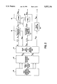
- FIG. 2 is a block diagram of the engine-pump control apparatus employed in the excavator having the above-mentioned arrangement in accordance with the present invention.
- FIG. 3 is a flow chart illustrating a method for controlling engine and pump operations in the excavator as shown in FIG. 1 in accordance with the present invention.
- FIG. 1 is a circuit diagram illustrating the overall system of an excavator to which an engine-pump control apparatus in accordance with the present invention is applied.
- the excavator includes an engine 80 as a power source, a pair of variable displacement type hydraulic pumps 25a and 25b driven by the engine 80, and a pair of hydraulic cylinders 105a and 105b as actuators respectively adapted to actuate corresponding work implements.
- a pair of solenoid controlled proportional oil quantity control valves 95a and 95b are disposed in oil lines connected between respective hydraulic pumps 25a and 25b and respective corresponding hydraulic cylinders 105a and 105b.
- Each of the oil quantity control valves 95a and 95b serves to switch connection of the corresponding oil line in accordance with a predetermined input signal and to adjust the delivery oil quantity to be proportional to the input signal.
- the excavator further includes a pair of solenoid controlled proportional valves 35a and 35b respectively adapted to adjust delivery oil quantities of the hydraulic pumps 25a and 25b in accordance with predetermined input signals.
- the excavator also includes control means for electronically controlling the overall operation of the excavator.
- the control means comprises a manipulation command unit 10 for work implements, a controller 85 provided with a microcomputer, an engine RPM detection unit 45, a pair of pump delivery oil quantity detection units 55a and 55b, and a pair of pump delivery pressure detection units 65a and 65b.
- the electronic-hydraulic system of the excavator is controlled to feed to the solenoid controlled proportional valves 35a and 35b the oil quantity proportional to the manipulation amount of the manipulation command unit 10 through a computation performed by the controller 85 on the basis of engine RPM data from the engine RPM detection unit 45 and pump delivery pressure variation data from the pump delivery pressure detection units 65a and 65b so that the suction horse power of each of the hydraulic pumps 25a and 25b corresponds to the maximum output horse power of the engine.
- the electronic-hydraulic system is also operated to control, by the oil quantity control valves 95a and 95b, the oil quantity fed to the hydraulic cylinders 105a and 105b such that it corresponds to the manipulation amount and manipulation ratio from the manipulation command unit 10.
- FIG. 2 is a block diagram of the engine-pump control apparatus employed in the excavator having the above-mentioned arrangement in accordance with the present invention.
- the engine-pump control apparatus includes a manipulation computation unit 20 for sensing a manipulation command signal from the manipulation command unit 10 and computing a reference input signal QREF for pump delivery oil quantity control indicative of the required pump delivery oil quantity value proportional to the manipulation amount based on the sensed manipulation command signal and a reference input signal V REF for work implement speed control indicative of the required work implement speed value proportional to the manipulation amount and manipulation ratio based on the sensed manipulation command signal.
- a manipulation computation unit 20 for sensing a manipulation command signal from the manipulation command unit 10 and computing a reference input signal QREF for pump delivery oil quantity control indicative of the required pump delivery oil quantity value proportional to the manipulation amount based on the sensed manipulation command signal and a reference input signal V REF for work implement speed control indicative of the required work implement speed value proportional to the manipulation amount and manipulation ratio based on the sensed manipulation command signal.
- the engine-pump control apparatus also includes an engine-pump control unit 70 for generating a current maximum pump delivery oil quantity signal QMAX through a control computation using an error EN (NREF - NREAL) between a reference input signal NREF for Engine RPM control for obtaining the maximum horse power of the engine and a real engine RPM signal NREAL and on the basis of a pump delivery pressure variation signal PVAR.
- the current maximum pump delivery oil quantity signal QMAX from the engine-pump control unit 70 is sent to a speed and pump delivery oil quantity control unit 30.
- the speed and pump oil delivery quantity adjustment unit 30 On the basis of the reference input signal QREF from the manipulation computation unit 20 and the current maximum pump delivery oil quantity signal QMAX from the engine-pump control unit 70, the speed and pump oil delivery quantity adjustment unit 30 re-adjusts the reference input signal QREF and the reference input signal VREF.
- the resultant signal from the speed and pump oil delivery quantity adjustment unit 30 is sent to a work implement speed control unit 40 and a pump oil delivery quantity control unit 50.
- the pump oil delivery quantity control unit 50 performs a controlled computation using an error EQ (QREF2 - QREAL) between the output signal from the speed and pump oil delivery quantity adjustment unit 30, namely, another reference input signal QREF2 for pump oil delivery quantity control and a real pump delivery oil quantity signal QREAL from the pump delivery oil quantity detection unit.
- the pump oil delivery quantity control unit 50 generates a pump oil delivery quantity control signal VPUMP which is, in turn, sent to an solenoid controlled proportional valve of a pump 60 so as to control the pump delivery oil quantity.
- the work implement speed control unit 40 performs a controlled computation using the output signal from the speed and pump oil delivery quantity adjustment unit 30, namely, the reference input signal VREF2 for work implement speed control.
- the work implement speed control unit 40 generates a work implement speed control signal Vucv which is, in turn, sent to a solenoid controlled proportional valve of the engine-pump control unit 70 so as to control the speed of the work implement.
- a discrimination is made about whether a manipulation command signal has been generated from the manipulation command unit 10.
- the procedure proceeds to a second step S2.
- the current maximum pump delivery oil quantity signal QMAX is set to be equal to a current minimum pump delivery oil quantity signal Qmin.
- the current maximum pump delivery oil quantity QuAx is determined as the current minimum pump delivery oil quantity Qmin mechanically deliverable by the pump.
- step S1 where it has been determined at step S1 that the manipulation command signal has been generated from the manipulation command unit 10, the procedure proceeds to a third step S3.
- a reference input signal NRFEF for engine RPM control inputting of a reference input signal NRFEF for engine RPM control, a real engine RPM signal NREAL and a pump delivery pressure P are executed.
- a computation of a pump delivery pressure variation signal PVAR is then executed on the basis of the input signals.
- a fourth step S4 is executed to compute an error signal EN (NREF - NREAL) between the reference input signal NREF and the real engine RPM signal NREAL both input at the third step S3.
- the engine-pump control unit 70 determines the rate RPM at full throttle, namely, the maximum engine horse power point as the reference RPM when the manipulation command signal from the manipulation command unit 10 has been generated.
- the rate RPM at full throttle namely, the maximum engine horse power point as the reference RPM when the manipulation command signal from the manipulation command unit 10 has been generated.
- the current maximum pump delivery oil quantity is optimally decreased in order to decrease the suction horse power of the pump. This is achieved by controlled computations of the pump delivery pressure variation signal PVAR and the RPM error.
- the speed and pump oil delivery quantity adjustment unit 30 adjusts the reference input signal VREF for work implement speed control and the reference input signal QREF2 for pump delivery oil quantity control.
- the engine-pump control apparatus of the present invention which is applied to construction equipment with work implement using a plurality of variable displacement pumps and a plurality of hydraulic cylinders as their actuators, prevents a stall phenomenon of the engine due to an overload generated in process of working, a reduction in output due to a variation in working circumstance and a reduction in output due to a variation in condition of the engine by the lapse of time.
- the engine-pump control apparatus of the present invention also utilizes the output of the engine highly in a wide load range, thereby achieving an enhancement in workability per power.
- the work can be automated in accordance with the present invention because the speed of each work implement and the speed ratio of the work implement to each other working members associated therewith are optimally controlled to correspond to the manipulation amount and manipulation ratio based on the manipulation command signal irrespective of the variations in working circumstance and load pressure. Furthermore, improvements In workability and working efficiency are obtained.
Abstract
Description
Claims (5)
Applications Claiming Priority (2)
| Application Number | Priority Date | Filing Date | Title |
|---|---|---|---|
| KR93-31450 | 1993-12-30 | ||
| KR1019930031450A KR950019129A (en) | 1993-12-30 | 1993-12-30 | Engine-pump control device and method of hydraulic construction machine |
Publications (1)
| Publication Number | Publication Date |
|---|---|
| US5527156A true US5527156A (en) | 1996-06-18 |
Family
ID=19374439
Family Applications (1)
| Application Number | Title | Priority Date | Filing Date |
|---|---|---|---|
| US08/334,217 Expired - Fee Related US5527156A (en) | 1993-12-30 | 1994-11-04 | Apparatus for and method of controlling engine and pumps of hydraulic construction equipment |
Country Status (4)
| Country | Link |
|---|---|
| US (1) | US5527156A (en) |
| JP (1) | JP3114151B2 (en) |
| KR (1) | KR950019129A (en) |
| DE (1) | DE4440304C2 (en) |
Cited By (29)
| Publication number | Priority date | Publication date | Assignee | Title |
|---|---|---|---|---|
| US5639218A (en) * | 1993-05-27 | 1997-06-17 | Daikin Industries, Ltd. | High pressure water pump system having a reserve booster pump |
| WO1999027197A2 (en) * | 1997-11-26 | 1999-06-03 | Case Corporation | Electronic control for a two-axis work implement |
| US5913663A (en) * | 1994-02-18 | 1999-06-22 | Brueninghaus Hydromatik Gmbh | Device for regulating the total power of at least two variable displacement hydrostatic pumps |
| US5944492A (en) * | 1996-12-27 | 1999-08-31 | Shin Caterpillar Mitsubishi Ltd. | Hydraulic pump control system |
| US5999872A (en) * | 1996-02-15 | 1999-12-07 | Kabushiki Kaisha Kobe Seiko Sho | Control apparatus for hydraulic excavator |
| US6115660A (en) * | 1997-11-26 | 2000-09-05 | Case Corporation | Electronic coordinated control for a two-axis work implement |
| US6216456B1 (en) | 1999-11-15 | 2001-04-17 | Caterpillar Inc. | Load sensing hydraulic control system for variable displacement pump |
| US6305419B1 (en) | 2000-07-14 | 2001-10-23 | Clark Equipment Company | Variable pilot pressure control for pilot valves |
| US6684636B2 (en) | 2001-10-26 | 2004-02-03 | Caterpillar Inc | Electro-hydraulic pump control system |
| WO2004033806A1 (en) * | 2002-10-08 | 2004-04-22 | Volvo Construction Equipment Holding Sweden Ab | A method and a device for controlling a vehicle and a computer program for performing the method |
| US20040261407A1 (en) * | 2003-06-30 | 2004-12-30 | Hongliu Du | Method and apparatus for controlling a hydraulic motor |
| US6907401B1 (en) | 2000-03-13 | 2005-06-14 | Verizon Corporate Services Group Inc. | Portal switch for electronic commerce |
| US7018178B2 (en) * | 2002-04-03 | 2006-03-28 | Borgwarner Inc. | Variable displacement pump and control therefore for supplying lubricant to an engine |
| US20060104823A1 (en) * | 2002-04-03 | 2006-05-18 | Borgwarner Inc. | Hydraulic pump with variable flow and variable pressure and electric control |
| US20060182636A1 (en) * | 2003-02-20 | 2006-08-17 | Monika Ivantysynova | Method for controlling a hydraulic system of a mobile working machine |
| US20070204604A1 (en) * | 2004-04-08 | 2007-09-06 | Komatsu Ltd. | Hydraulic Drive Device for Work Machine |
| US20070227137A1 (en) * | 2004-05-07 | 2007-10-04 | Komatsu Ltd. | Hydraulic Drive Device For Work Machine |
| US20080098991A1 (en) * | 2006-10-26 | 2008-05-01 | Caterpillar, Inc. | Selective displacement control of multi-plunger fuel pump |
| US20100322791A1 (en) * | 2007-11-01 | 2010-12-23 | Sauer-Danfoss Aps | Hydraulic system with supplement pump |
| US20110020159A1 (en) * | 2007-11-01 | 2011-01-27 | Onno Kuttler | Fluid working machine |
| US20110318155A1 (en) * | 2009-03-06 | 2011-12-29 | Komatsu Ltd. | Construction Machine, Method for Controlling Construction Machine, and Program for Causing Computer to Execute the Method |
| US20120305258A1 (en) * | 2011-06-06 | 2012-12-06 | Benton Frederick Baugh | Method for increasing subsea accumulator volume |
| US8726785B2 (en) | 2007-10-04 | 2014-05-20 | Westport Power Inc. | Hydraulic drive system and diagnostic control strategy for improved operation |
| US9267446B2 (en) | 2012-06-15 | 2016-02-23 | Caterpillar Paving Products Inc. | Engine speed management control system for cold planers |
| US20160146202A1 (en) * | 2013-07-30 | 2016-05-26 | Parker-Hannifin Corporation | Overshoot reduction on pump controls |
| US20160178052A1 (en) * | 2014-12-19 | 2016-06-23 | GM Global Technology Operations LLC | Minimal line pressure disturbance pump switching valve |
| US20190049001A1 (en) * | 2017-08-10 | 2019-02-14 | Honda Motor Co., Ltd. | Hydraulic control device |
| DE102009025707B4 (en) * | 2009-06-20 | 2021-06-02 | Robert Bosch Gmbh | Device for controlling a system with hydraulic circuits |
| US11220804B2 (en) * | 2019-07-26 | 2022-01-11 | Robert Bosch Gmbh | Hydraulic pressurizing medium supply assembly for a mobile work machine, and method |
Families Citing this family (12)
| Publication number | Priority date | Publication date | Assignee | Title |
|---|---|---|---|---|
| JP3256370B2 (en) * | 1994-03-17 | 2002-02-12 | 新キャタピラー三菱株式会社 | Hydraulic excavator pump control device |
| DE19602729C2 (en) * | 1995-12-06 | 2001-03-01 | Mannesmann Vdo Ag | Method and arrangement for controlling an electro-hydraulic pressure supply for an auxiliary power device of a motor vehicle |
| JP3521981B2 (en) * | 1994-11-28 | 2004-04-26 | 株式会社小松製作所 | Construction machine traction force control device and control method thereof |
| JP4474497B2 (en) * | 2002-11-13 | 2010-06-02 | 住友建機株式会社 | Hydraulic circuit for construction machinery |
| KR101151562B1 (en) * | 2004-12-29 | 2012-05-30 | 두산인프라코어 주식회사 | An apparatus for controlling the hydraulic pump of a wheel loader |
| DE102006009063A1 (en) * | 2006-02-27 | 2007-08-30 | Liebherr-Werk Nenzing Gmbh, Nenzing | Method and device for controlling a hydraulic drive system |
| KR101293379B1 (en) * | 2006-07-13 | 2013-08-05 | 두산인프라코어 주식회사 | Control method of hydraulic pump |
| DE102008054880A1 (en) * | 2008-12-18 | 2010-07-01 | Deere & Company, Moline | hydraulic system |
| US8429908B2 (en) | 2009-12-17 | 2013-04-30 | Deere & Company | Hydraulic system |
| DE102013211443A1 (en) * | 2013-06-19 | 2014-12-24 | Robert Bosch Gmbh | Mobile work machine with workspace monitoring |
| CN106884833A (en) * | 2017-04-17 | 2017-06-23 | 泸州市长江液压件装备有限公司 | A kind of hydraulic servo synchronization system |
| CN109235531A (en) * | 2018-11-08 | 2019-01-18 | 北京拓疆者智能科技有限公司 | Rear dress unmanned systems and excavator for excavator |
Citations (11)
| Publication number | Priority date | Publication date | Assignee | Title |
|---|---|---|---|---|
| US4451893A (en) * | 1980-10-17 | 1984-05-29 | Hitachi Construction Machinery Co., Ltd. | Control method and control system for hydrostatic drive system |
| US4637781A (en) * | 1984-03-30 | 1987-01-20 | Kabushiki Kaisha Komatsu Seisakusho | Torque regulating system for fluid operated pump displacement control systems |
| US4672811A (en) * | 1984-04-17 | 1987-06-16 | Kabushiki Kaisha Komatsu Seisakubsho | Vehicle speed control system |
| US4773369A (en) * | 1985-02-28 | 1988-09-27 | Kabushiki Kaisha Komatsu Seisakusho | Method of controlling an output of an internal combustion engine and/or a variable displacement hydraulic pump driven by the engine |
| US4809504A (en) * | 1986-01-11 | 1989-03-07 | Hitachi Construction Machinery Co., Ltd. | Control system for controlling input power to variable displacement hydraulic pumps of a hydraulic system |
| US4846046A (en) * | 1987-03-09 | 1989-07-11 | Hitachi Construction Machinery Co., Ltd. | Hydraulic drive circuit system |
| US4904161A (en) * | 1986-08-15 | 1990-02-27 | Kabushiki Kaisha Komatsu Seisakusho | Apparatus for controlling hydrualic pump |
| US5129230A (en) * | 1990-06-19 | 1992-07-14 | Hitachi Construction Machinery Co., Ltd. | Control system for load sensing hydraulic drive circuit |
| US5197860A (en) * | 1987-01-30 | 1993-03-30 | Kimio Nishida | Hydraulic apparatus for construction machines |
| US5226800A (en) * | 1989-09-22 | 1993-07-13 | Kabushiki Kaisha Komatsu Seisakusho | Displacement controlling circuit system for variable displacement pump |
| US5352095A (en) * | 1992-06-10 | 1994-10-04 | Shin Caterpillar Mitsubishi Ltd. | Method for controlling hydraulic pump driven by engine |
Family Cites Families (5)
| Publication number | Priority date | Publication date | Assignee | Title |
|---|---|---|---|---|
| IN171213B (en) * | 1988-01-27 | 1992-08-15 | Hitachi Construction Machinery | |
| JP2670815B2 (en) * | 1988-07-29 | 1997-10-29 | 株式会社小松製作所 | Control equipment for construction machinery |
| EP0432266B2 (en) * | 1989-01-18 | 1997-08-13 | Hitachi Construction Machinery Co., Ltd. | Hydraulic driving unit for construction machinery |
| KR940009219B1 (en) * | 1989-03-30 | 1994-10-01 | 히다찌 겐끼 가부시기가이샤 | Hydraulic driving apparatus of caterpillar vehicle |
| KR950008533B1 (en) * | 1991-11-30 | 1995-07-31 | 삼성중공업주식회사 | Control devices output of hydraulic pump |
-
1993
- 1993-12-30 KR KR1019930031450A patent/KR950019129A/en active IP Right Grant
-
1994
- 1994-11-04 US US08/334,217 patent/US5527156A/en not_active Expired - Fee Related
- 1994-11-08 JP JP06298983A patent/JP3114151B2/en not_active Expired - Fee Related
- 1994-11-11 DE DE4440304A patent/DE4440304C2/en not_active Expired - Fee Related
Patent Citations (11)
| Publication number | Priority date | Publication date | Assignee | Title |
|---|---|---|---|---|
| US4451893A (en) * | 1980-10-17 | 1984-05-29 | Hitachi Construction Machinery Co., Ltd. | Control method and control system for hydrostatic drive system |
| US4637781A (en) * | 1984-03-30 | 1987-01-20 | Kabushiki Kaisha Komatsu Seisakusho | Torque regulating system for fluid operated pump displacement control systems |
| US4672811A (en) * | 1984-04-17 | 1987-06-16 | Kabushiki Kaisha Komatsu Seisakubsho | Vehicle speed control system |
| US4773369A (en) * | 1985-02-28 | 1988-09-27 | Kabushiki Kaisha Komatsu Seisakusho | Method of controlling an output of an internal combustion engine and/or a variable displacement hydraulic pump driven by the engine |
| US4809504A (en) * | 1986-01-11 | 1989-03-07 | Hitachi Construction Machinery Co., Ltd. | Control system for controlling input power to variable displacement hydraulic pumps of a hydraulic system |
| US4904161A (en) * | 1986-08-15 | 1990-02-27 | Kabushiki Kaisha Komatsu Seisakusho | Apparatus for controlling hydrualic pump |
| US5197860A (en) * | 1987-01-30 | 1993-03-30 | Kimio Nishida | Hydraulic apparatus for construction machines |
| US4846046A (en) * | 1987-03-09 | 1989-07-11 | Hitachi Construction Machinery Co., Ltd. | Hydraulic drive circuit system |
| US5226800A (en) * | 1989-09-22 | 1993-07-13 | Kabushiki Kaisha Komatsu Seisakusho | Displacement controlling circuit system for variable displacement pump |
| US5129230A (en) * | 1990-06-19 | 1992-07-14 | Hitachi Construction Machinery Co., Ltd. | Control system for load sensing hydraulic drive circuit |
| US5352095A (en) * | 1992-06-10 | 1994-10-04 | Shin Caterpillar Mitsubishi Ltd. | Method for controlling hydraulic pump driven by engine |
Cited By (53)
| Publication number | Priority date | Publication date | Assignee | Title |
|---|---|---|---|---|
| US5639218A (en) * | 1993-05-27 | 1997-06-17 | Daikin Industries, Ltd. | High pressure water pump system having a reserve booster pump |
| US5913663A (en) * | 1994-02-18 | 1999-06-22 | Brueninghaus Hydromatik Gmbh | Device for regulating the total power of at least two variable displacement hydrostatic pumps |
| US5999872A (en) * | 1996-02-15 | 1999-12-07 | Kabushiki Kaisha Kobe Seiko Sho | Control apparatus for hydraulic excavator |
| CN1089867C (en) * | 1996-12-27 | 2002-08-28 | 新履带三菱株式会社 | Hydraulic pump control system |
| US5944492A (en) * | 1996-12-27 | 1999-08-31 | Shin Caterpillar Mitsubishi Ltd. | Hydraulic pump control system |
| US6115660A (en) * | 1997-11-26 | 2000-09-05 | Case Corporation | Electronic coordinated control for a two-axis work implement |
| US6233511B1 (en) | 1997-11-26 | 2001-05-15 | Case Corporation | Electronic control for a two-axis work implement |
| WO1999027197A2 (en) * | 1997-11-26 | 1999-06-03 | Case Corporation | Electronic control for a two-axis work implement |
| WO1999027197A3 (en) * | 1997-11-26 | 2003-05-08 | Case Corp | Electronic control for a two-axis work implement |
| US6216456B1 (en) | 1999-11-15 | 2001-04-17 | Caterpillar Inc. | Load sensing hydraulic control system for variable displacement pump |
| US6907401B1 (en) | 2000-03-13 | 2005-06-14 | Verizon Corporate Services Group Inc. | Portal switch for electronic commerce |
| US6305419B1 (en) | 2000-07-14 | 2001-10-23 | Clark Equipment Company | Variable pilot pressure control for pilot valves |
| US6684636B2 (en) | 2001-10-26 | 2004-02-03 | Caterpillar Inc | Electro-hydraulic pump control system |
| US20060104823A1 (en) * | 2002-04-03 | 2006-05-18 | Borgwarner Inc. | Hydraulic pump with variable flow and variable pressure and electric control |
| US7726948B2 (en) | 2002-04-03 | 2010-06-01 | Slw Automotive Inc. | Hydraulic pump with variable flow and variable pressure and electric control |
| US7018178B2 (en) * | 2002-04-03 | 2006-03-28 | Borgwarner Inc. | Variable displacement pump and control therefore for supplying lubricant to an engine |
| US20060127229A1 (en) * | 2002-04-03 | 2006-06-15 | Borgwarner Inc. | Variable displacement pump and control therefor |
| US7396214B2 (en) | 2002-04-03 | 2008-07-08 | Borgwarner Inc. | Variable displacement pump and control therefor |
| WO2004033806A1 (en) * | 2002-10-08 | 2004-04-22 | Volvo Construction Equipment Holding Sweden Ab | A method and a device for controlling a vehicle and a computer program for performing the method |
| US20050241304A1 (en) * | 2002-10-08 | 2005-11-03 | Volvo Construction Equipment Holding Sweden Ab | A method and a device for controlling a vehicle and a computer program for performing the method |
| US7225615B2 (en) | 2002-10-08 | 2007-06-05 | Volvo Construction Equipment Holding Sweden Ab | Method and a device for controlling a vehicle and a computer program for performing the method |
| CN100445478C (en) * | 2002-10-08 | 2008-12-24 | 沃尔沃建造设备控股(瑞典)有限公司 | A method and a device for controlling a vehicle and a computer program for performing the method |
| US7386978B2 (en) * | 2003-02-20 | 2008-06-17 | Cnh America Llc | Method for controlling a hydraulic system of a mobile working machine |
| US20060182636A1 (en) * | 2003-02-20 | 2006-08-17 | Monika Ivantysynova | Method for controlling a hydraulic system of a mobile working machine |
| US20040261407A1 (en) * | 2003-06-30 | 2004-12-30 | Hongliu Du | Method and apparatus for controlling a hydraulic motor |
| US6848254B2 (en) | 2003-06-30 | 2005-02-01 | Caterpillar Inc. | Method and apparatus for controlling a hydraulic motor |
| US20070204604A1 (en) * | 2004-04-08 | 2007-09-06 | Komatsu Ltd. | Hydraulic Drive Device for Work Machine |
| US7533527B2 (en) * | 2004-04-08 | 2009-05-19 | Komatsu Ltd. | Hydraulic drive device for work machine |
| US20070227137A1 (en) * | 2004-05-07 | 2007-10-04 | Komatsu Ltd. | Hydraulic Drive Device For Work Machine |
| US7631495B2 (en) | 2004-05-07 | 2009-12-15 | Komatsu Ltd. | Hydraulic drive device for work machine |
| US8136508B2 (en) * | 2006-10-26 | 2012-03-20 | Caterpillar Inc. | Selective displacement control of multi-plunger fuel pump |
| US20080098991A1 (en) * | 2006-10-26 | 2008-05-01 | Caterpillar, Inc. | Selective displacement control of multi-plunger fuel pump |
| US8015964B2 (en) * | 2006-10-26 | 2011-09-13 | David Norman Eddy | Selective displacement control of multi-plunger fuel pump |
| US20110290219A1 (en) * | 2006-10-26 | 2011-12-01 | Caterpillar Inc. | Selective displacement control of multi-plunger fuel pump |
| US8726785B2 (en) | 2007-10-04 | 2014-05-20 | Westport Power Inc. | Hydraulic drive system and diagnostic control strategy for improved operation |
| US20110020159A1 (en) * | 2007-11-01 | 2011-01-27 | Onno Kuttler | Fluid working machine |
| US8668465B2 (en) * | 2007-11-01 | 2014-03-11 | Sauer-Danfoss Aps | Hydraulic system with supplement pump |
| US20100322791A1 (en) * | 2007-11-01 | 2010-12-23 | Sauer-Danfoss Aps | Hydraulic system with supplement pump |
| US8905732B2 (en) | 2007-11-01 | 2014-12-09 | Danfoss Power Solutions Aps | Fluid working machine |
| US20110318155A1 (en) * | 2009-03-06 | 2011-12-29 | Komatsu Ltd. | Construction Machine, Method for Controlling Construction Machine, and Program for Causing Computer to Execute the Method |
| US8930090B2 (en) * | 2009-03-06 | 2015-01-06 | Komatsu Ltd. | Construction equipment, method for controlling construction equipment, and program for causing computer to execute the method |
| DE102009025707B4 (en) * | 2009-06-20 | 2021-06-02 | Robert Bosch Gmbh | Device for controlling a system with hydraulic circuits |
| US9291036B2 (en) * | 2011-06-06 | 2016-03-22 | Reel Power Licensing Corp. | Method for increasing subsea accumulator volume |
| US20150354309A1 (en) * | 2011-06-06 | 2015-12-10 | Reel Power Licensing Corp | Method for increasing subsea accumulator volume |
| US9885221B2 (en) * | 2011-06-06 | 2018-02-06 | Reel Power Licensing Corp. | Method for increasing subsea accumulator volume |
| US20120305258A1 (en) * | 2011-06-06 | 2012-12-06 | Benton Frederick Baugh | Method for increasing subsea accumulator volume |
| US9267446B2 (en) | 2012-06-15 | 2016-02-23 | Caterpillar Paving Products Inc. | Engine speed management control system for cold planers |
| US20160146202A1 (en) * | 2013-07-30 | 2016-05-26 | Parker-Hannifin Corporation | Overshoot reduction on pump controls |
| US20160178052A1 (en) * | 2014-12-19 | 2016-06-23 | GM Global Technology Operations LLC | Minimal line pressure disturbance pump switching valve |
| CN105736692A (en) * | 2014-12-19 | 2016-07-06 | 通用汽车环球科技运作有限责任公司 | Minimal line pressure disturbance pump switching valve |
| US20190049001A1 (en) * | 2017-08-10 | 2019-02-14 | Honda Motor Co., Ltd. | Hydraulic control device |
| US10816092B2 (en) * | 2017-08-10 | 2020-10-27 | Honda Motor Co., Ltd. | Hydraulic control device including first and second hydraulic sensors |
| US11220804B2 (en) * | 2019-07-26 | 2022-01-11 | Robert Bosch Gmbh | Hydraulic pressurizing medium supply assembly for a mobile work machine, and method |
Also Published As
| Publication number | Publication date |
|---|---|
| KR950019129A (en) | 1995-07-22 |
| JPH07208404A (en) | 1995-08-11 |
| DE4440304C2 (en) | 2001-08-02 |
| JP3114151B2 (en) | 2000-12-04 |
| DE4440304A1 (en) | 1995-07-06 |
Similar Documents
| Publication | Publication Date | Title |
|---|---|---|
| US5527156A (en) | Apparatus for and method of controlling engine and pumps of hydraulic construction equipment | |
| EP1553231B1 (en) | Control device for hydraulic drive machine | |
| US6286412B1 (en) | Method and system for electrohydraulic valve control | |
| EP0644335B1 (en) | Hydraulic drive for hydraulic work machine | |
| EP0432266B1 (en) | Hydraulic driving unit for construction machinery | |
| US5630317A (en) | Controller for hydraulic drive machine | |
| JP3210221B2 (en) | Construction machine control circuit | |
| EP0504415B1 (en) | Control system of hydraulic pump | |
| US6170262B1 (en) | Control device for hydraulically driven equipment | |
| JP3381952B2 (en) | Fluid pressure control device | |
| JPH07101041B2 (en) | Proportional valve controller for fluid system | |
| JP3115887B2 (en) | Variable circuit of pump displacement in closed center load sensing system | |
| US5101629A (en) | Hydraulic circuit system for working machine | |
| JP2651079B2 (en) | Hydraulic construction machinery | |
| JPH07197907A (en) | Hydraulic construction machine | |
| JP3491940B2 (en) | Control device for variable displacement hydraulic pump | |
| JP2677803B2 (en) | Hydraulic drive | |
| JPH09189302A (en) | Speed control device of hydraulic actuator | |
| KR100433186B1 (en) | Control system of an engine and pump output for Excavator | |
| EP0632167A2 (en) | Apparatus and method for controlling hydraulic construction equipment | |
| JP2920057B2 (en) | Hydraulic control device for construction machinery | |
| US5845223A (en) | Apparatus and method for controlling actuators of hydraulic construction equipment | |
| US20030051470A1 (en) | Control system for hydraulic equipment attachments | |
| JP3444503B2 (en) | Control device for hydraulic drive machine | |
| JP3175992B2 (en) | Control device for hydraulic drive machine |
Legal Events
| Date | Code | Title | Description |
|---|---|---|---|
| AS | Assignment |
Owner name: SAMSUNG HEAVY INDUSTRY CO., LTD., KOREA, REPUBLIC Free format text: ASSIGNMENT OF ASSIGNORS INTEREST;ASSIGNOR:SONG, MYUNG-HOON;REEL/FRAME:007217/0727 Effective date: 19940505 |
|
| FEPP | Fee payment procedure |
Free format text: PAYOR NUMBER ASSIGNED (ORIGINAL EVENT CODE: ASPN); ENTITY STATUS OF PATENT OWNER: LARGE ENTITY |
|
| AS | Assignment |
Owner name: VOLVO CONSTRUCTION EQUIPMENT KOREA CO., LTD., KORE Free format text: ASSIGNMENT OF ASSIGNORS INTEREST;ASSIGNOR:SAMSUNG HEAVY INDUSTRIES CO., LTD.;REEL/FRAME:009561/0648 Effective date: 19981017 |
|
| FPAY | Fee payment |
Year of fee payment: 4 |
|
| AS | Assignment |
Owner name: VOLVO CONSTRUCTION EQUIPMENT HOLDING SWEDEN AB, SW Free format text: ASSIGNMENT OF ASSIGNORS INTEREST;ASSIGNOR:VOLVO CONSTRUCTION EQUIPMENT KOREA CO., LTD.;REEL/FRAME:012435/0734 Effective date: 20011120 |
|
| LAPS | Lapse for failure to pay maintenance fees | ||
| FP | Lapsed due to failure to pay maintenance fee |
Effective date: 20040618 |
|
| STCH | Information on status: patent discontinuation |
Free format text: PATENT EXPIRED DUE TO NONPAYMENT OF MAINTENANCE FEES UNDER 37 CFR 1.362 |