EP0546212B1 - Induktionsofen mit geneigter Spule - Google Patents
Induktionsofen mit geneigter Spule Download PDFInfo
- Publication number
- EP0546212B1 EP0546212B1 EP91121256A EP91121256A EP0546212B1 EP 0546212 B1 EP0546212 B1 EP 0546212B1 EP 91121256 A EP91121256 A EP 91121256A EP 91121256 A EP91121256 A EP 91121256A EP 0546212 B1 EP0546212 B1 EP 0546212B1
- Authority
- EP
- European Patent Office
- Prior art keywords
- crucible
- center axis
- side wall
- coil
- induction furnace
- Prior art date
- Legal status (The legal status is an assumption and is not a legal conclusion. Google has not performed a legal analysis and makes no representation as to the accuracy of the status listed.)
- Expired - Lifetime
Links
- 230000006698 induction Effects 0.000 title claims abstract description 30
- 238000004804 winding Methods 0.000 claims abstract description 9
- 230000001154 acute effect Effects 0.000 claims abstract description 6
- 239000000463 material Substances 0.000 claims description 29
- 229910052751 metal Inorganic materials 0.000 claims description 28
- 239000002184 metal Substances 0.000 claims description 28
- 239000002893 slag Substances 0.000 claims description 27
- 235000002918 Fraxinus excelsior Nutrition 0.000 claims description 4
- 239000002956 ash Substances 0.000 claims description 4
- 239000000428 dust Substances 0.000 claims description 2
- 238000010891 electric arc Methods 0.000 claims description 2
- 239000010802 sludge Substances 0.000 claims description 2
- 230000014759 maintenance of location Effects 0.000 description 7
- 239000002801 charged material Substances 0.000 description 6
- 239000012768 molten material Substances 0.000 description 4
- 230000008018 melting Effects 0.000 description 3
- 238000002844 melting Methods 0.000 description 3
- 230000001174 ascending effect Effects 0.000 description 2
- 238000010438 heat treatment Methods 0.000 description 2
- 229910045601 alloy Inorganic materials 0.000 description 1
- 239000000956 alloy Substances 0.000 description 1
- 230000001419 dependent effect Effects 0.000 description 1
- 230000005672 electromagnetic field Effects 0.000 description 1
- 230000004907 flux Effects 0.000 description 1
- 239000000155 melt Substances 0.000 description 1
- 150000002736 metal compounds Chemical class 0.000 description 1
- 150000002739 metals Chemical class 0.000 description 1
- 230000002093 peripheral effect Effects 0.000 description 1
- 238000011084 recovery Methods 0.000 description 1
Images

Classifications
-
- H—ELECTRICITY
- H05—ELECTRIC TECHNIQUES NOT OTHERWISE PROVIDED FOR
- H05B—ELECTRIC HEATING; ELECTRIC LIGHT SOURCES NOT OTHERWISE PROVIDED FOR; CIRCUIT ARRANGEMENTS FOR ELECTRIC LIGHT SOURCES, IN GENERAL
- H05B6/00—Heating by electric, magnetic or electromagnetic fields
- H05B6/02—Induction heating
- H05B6/22—Furnaces without an endless core
- H05B6/24—Crucible furnaces
Definitions
- This invention relates to an induction furnace for use in melting or processing a material, such as used dry batteries (abbreviated to UDB), electric arc furnace dust (EFD), activated sludge burned ashes (ASA), ashes of garbage incineration, and the like. It is to be noted that such a material to be processed will be simply called a material hereinunder.
- a material such as used dry batteries (abbreviated to UDB), electric arc furnace dust (EFD), activated sludge burned ashes (ASA), ashes of garbage incineration, and the like.
- an induction furnace of the type described comprises a crucible for charging or dumping a material to be processed and a coil member wound around the crucible.
- An a.c. exciting current of a low frequency, for example, 50-60 Hz is caused to flow from an a.c. current source through the coil member to induce an electromagnetic flux within the crucible.
- an eddy-current flows in the material which is charged into the crucible through an inlet port.
- the material is heated by the eddy-current within the crucible.
- induction heating is carried out in the crucible.
- the material is agitated to be fused and is sent through an outlet port in the form of a slag or a molten bath.
- Such a general induction furnace is disclosed in US-A-1 872 990.
- FR-A-2 316 828 discloses an induction melting furnace suitable for melting metals and alloys at a laboratory scale.
- each of charged materials is heated from the inlet port to the outlet port for a uniform retention time. Otherwise, a uniform slag and metal product can not be ejected through the outlet port.
- an induction furnace comprising a crucible which has a crucible center axis and an axial symmetrical configuration with respect to the crucible center axis.
- the crucible is outlined by an inverted frustum contour, namely, an inverted circular truncated contour.
- An induction coil is wound around the crucible so that the crucible center axis becomes a winding axis.
- the inlet and the outlet ports are located on both sides of the crucible center axis and are adjacent to the crucible side wall as compared with the crucible center axis.
- An induction furnace to which this invention is applicable comprises a crucible which has a crucible center axis and an axial symmetrical configuration with respect to the crucible center axis and an induction coil wound around the crucible.
- the crucible has a crucible bottom, a crucible side wall contiguous to the crucible bottom, and a crucible cover covered on the crucible side wall to define an internal space together with the crucible bottom and the crucible side wall.
- the crucible center axis is extended through the crucible bottom and the crucible cover.
- the coil member is wound around the crucible side wall so that the coil member has a hypothetical coil center axis oblique with respect to the crucible center axis at an acute angle and the side wall has a circular truncated configuration such that said crucible side wall upper portion is wider in area than said crucible bottom portion.
- the illustrated induction furnace comprises a cylindrical crucible 10 which has a cylinder center axis, a crucible bottom, a cylindrical side wall standing upright from the crucible bottom, a crucible cover mounted on the cylindrical side wall to define an internal space together with the crucible bottom and the cylindrical side wall.
- the cylindrical side wall is wound by a coil member 11 which has a coil center axis substantially coincident with the cylinder center axis. In other words, the coil member 11 is wound around the cylindrical side wall so that the coil member 11 is perpendicular to the cylindrical center axis. As shown in Fig. 1, the illustrated coil member 11 is wound at a lower portion of the crucible 10.
- a main inlet port 12a, a supplementary inlet port 12b, and an exhaust port 13 are formed to charge or dump a material, to supplementarily charge another material, and to exhaust an inner gas, respectively.
- the illustrated main inlet port 12a is vertically extended from the crucible cover and substantially coincident with the crucible center axis.
- the supplementary inlet port 12b and the exhaust port 13 are located on both sides of the main inlet port 12a on the crucible cover with both the supplementary inlet port 12b and the exhaust port 13 inclined relative to the main inlet port 12a.
- a basin 15 is attached through a tap hole or an outlet port 16 and is associated with the inner space of the crucible 10. As illustrated in Fig. 1, the basin 15 is located above the coil member 11. A slag bath and a metal bath are held in the crucible 10 as a result of induction heating and thereafter flows out of the crucible 10 into the basin 15 through the outlet port 16. The slag bath and the metal bath are discharged from the basin 15 through a weir 17 out of the basin 15.
- the materials which may be of a metal or include a metal compound are successively charged through the inlet port 12a into the crucible 10, with an a.c. exciting current caused to flow through the coil member 11.
- the material is molten and reduced into metal and/or slag baths.
- the slag bath floats on the metal bath, as depicted at dotted portions in Fig. 1.
- a gaseous material is exhausted through the exhaust port 13 into an exhaust gas recovery and treatment apparatus (not shown).
- a level of the slag bath increases in the crucible as a reactive material increases in the slag bath.
- the molten material flows out of the crucible 10 through the outlet port 16 into the basin 15 because the crucible 10 is associated with the basin 15. This shows that the slag and the metal baths partially flow out of the crucible 10 into the basin 15. Subsequently, the molten material is continuously discharged from the basin 15 through the weir 17 with the slag bath interrupted in the basin 15, as illustrated in Fig. 1.
- the material is successively charged at the center of the crucible 10 and the molten material is successively discharged through the outlet port 16 on the crucible side wall.
- the charged material is moved along an upper region of the slag bath towards a peripheral portion of the slag bath by a swirling-up motion which results from an electromagnetic field. Thereafter, the charged material is submerged downwards of the metal bath.
- a retention time is defined in connection with the slag bath, as known in the art. Namely, the retention time is determined by a volume of the slag bath and a feed rate of the material and is irregularly variable. The material which moves directly to the outlet port 16 reaches the outlet port 16 before it is melted in the crucible 10. This means that the retention time becomes very short for such a material and that a short path takes place in the slag bath. In this case, the material is not preferably processed in the crucible 10, as pointed out in the preamble of the instant specification.
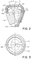
- an induction furnace comprises a crucible 10a of a circular truncated or frustum configuration.
- the crucible 10a has a crucible bottom, a crucible side wall contiguous to the crucible bottom, and a crucible cover mounted on the crucible side wall.
- the crucible side wall has a lower portion adjacent to the crucible bottom and an upper portion wider than the lower portion in section, as shown in Fig. 2.
- the illustrated crucible 10a has an axial symmetrical configuration with respect to the crucible center axis CL1.
- a coil member 11a is obliquely wound around the crucible side wall so that the coil member has a coil center axis CL2 which is oblique with respect to the crucible center axis CL1.
- the coil center axis CL2 is inclined to the crucible center axis CL1 at an angle ⁇ between 3° and 10°.
- the acute angle ⁇ is equal to 4°.
- the coil member 11a is composed of a plurality of windings or turns which are oblique with respect to the crucible center axis CL1 and each of which has the highest position and the lowest position on the crucible side wall.
- an inlet port 12c is formed to successively charge materials S into the crucible 10a therethrough.
- the inlet port 12c is displaced or eccentrical relative to the crucible center axis CL1, as shown in Figs. 2 and 3. It is to be noted in Figs. 2 and 3 that the inlet port 12c is adjacent to the highest positions of the windings of the coil member lla and is remote from the lowest positions of the coil.
- a tap hole or an outlet port 16a is formed on the upper portion of the crucible side wall and is adjacent to the lowest positions of the coil, as best shown in Fig. 2.
- the inlet port 12c, the outlet port 16a, and the crucible center axis CL1 are arranged in a line, as illustrated in Fig. 3.
- the outlet port 16a is placed along a straight line extended through both the inlet port 12c and the crucible center axis CL1 and is located on an opposite side of the inlet port 12c with respect to the crucible center axis CL1.
- the outlet port 16a is coupled to a basin (not shown in this figure), like in Fig. 1 while an exhaust port is also formed on the crucible cover to exhaust the gas from the crucible 10a, like in Fig. 1, although such an exhaust port is omitted from Figs. 2 and 3.
- the exciting current is caused to flow through the coil member 11a from an a.c. current source (not shown) and that an eddy current flows in the metal bath in a known manner.
- the metal bath is moved within the crucible 10a swirling up along the crucible center axis CL1 in Fig. 2.
- the molten metal is moved or directed towards the crucible side wall when it reaches the metal bath surface and the crucible bottom and the slag floating on the metal bath moves in such a way that the lower part of the slag moves in the radial direction along with the metal surface movement while the upper part of the slag moves countercurrently to the lower part.
- the molten metal is submerged downwards and ascended upwards to form a descending and an ascending flow along the crucible side wall, as depicted at an arrow R.
- the descending and the ascending flows are joined together with each other to form a flow which is directed towards the coil center axis CL2.
- Such flows are collected from every direction around the coil center axis CL2 to be joined together on the coil center axis CL2 and are thereafter moved upwards and downwards.
- the molten metal flows around the coil center axis CL2, as depicted at arrows P1 and P2, on the metal bath surface.
- the highest point of the molten metal surface is located at the point H.P. which causes first the potential flow to occur from the highest point to the lowest point L.P. of the molten metal surface and then the stagnation of the molten metal and the slag results in the counter flow of the melts to the outlet port 16a, as depicted at arrows P1 and P2 in Fig. 3.
- the metal bath exhibits the metal bath surface convex upwards of Fig. 2 and has the maximum height peak along the coil center axis CL2.
- the coil center axis CL2 intersects the slag bath surface at the highest point (H.P.). This shows that a position of the maximum height peak depends on the angle ⁇ between the crucible center axis CL1 and the coil center axis CL2. Stated otherwise, the maximum height peak can be determined by an oblique angle of the coil member 11a.
- the molten material flows from the maximum height peak to a lower portion of the metal bath surface.
- a gradient takes place between the maximum height peak and the lower portion.
- a lowest point of the metal bath surface is adjacent to the outlet port 16a and is lower than a level of the slag bath surface at a position right under the inlet port 12c. Therefore, the gradient is formed between the position right under the inlet port 12c and the outlet port 16a around the maximum height peak.
- bifurcated flows depicted at P1 and P2 in Fig. 3 appear on the slag bath surface and are sent from the position right under the inlet port 12c to the outlet port 16a. From this fact, it is readily understood that each material charged through the inlet port 12a is bifurcated at the position right under the inlet port 12a and is caused to slowly flow along the crucible side wall towards the outlet port 16a. Each charged material is subjected to the agitating operation before it reaches the outlet port 16a. Consequently, each charged material is submerged into the metal bath.
Landscapes
- Physics & Mathematics (AREA)
- Electromagnetism (AREA)
- Crucibles And Fluidized-Bed Furnaces (AREA)
- Furnace Details (AREA)
- General Induction Heating (AREA)
Claims (6)
- Induktionsofen zur Verwendung beim Verarbeiten mindestens eines Materials, das ausgewählt ist aus einer Gruppe, die aus gebrauchten Trockenbatterien, Staub aus Elektrolichtbogenöfen, Aschen aus der Bioschlammverbrennung, Aschen aus der Müllverbrennung u. ä. besteht, um das Material zu einem Metall- und Schlackenbad einzuschmelzen, wobei:ein Tiegel (10a) einen Innenraum, eine Tiegelmittelachse und eine axialsymmetrische Konfiguration im Hinblick auf die Tiegelmittelachse hat und einen geschlossenen Tiegelbodenabschnitt und eine Tiegelseitenwand, wobei die Seitenwand einen offenen oberen Abschnitt hat und die Seitenwand an den Tiegelbodenabschnitt angrenzt, sowie einen auf dem oberen Abschnitt der Seitenwand angeordneten Tiegeldeckel hat, wobei die Tiegelmittelachse (CL1) durch den Tiegelbodenabschnitt und den Tiegeldeckel verläuft; dadurch gekennzeichnet, daßein Induktionsspulenteil (11a) so um die Tiegelseitenwand gewickelt ist, daß das Induktionsspulenteil eine Spulenmittelachse (CL2) hat, die schräg im Hinblick auf die Tiegelmittelachse (CL1) in einem spitzen Winkel ist, und daßdie Seitenwand eine solche Kreiskegelstumpfkonfiguration hat, daß der obere Abschnitt der Tiegelseitenwand eine breitere Fläche als der Tiegelbodenabschnitt hat.
- Induktionsofen nach Anspruch 1, dadurch gekennzeichnet, daß der Tiegeldeckel einen Einlaßanschluß (12c) zum Einleiten des Materials in den Innenraum bildet, während die Seitenwand einen Auslaßanschluß (16a) zum Entnehmen der Schlacke aus dem Innenraum bildet.
- Induktionsofen nach Anspruch 1 oder 2, dadurch gekennzeichnet, daß der Einlaßanschluß (12c) auf einer Geraden angeordnet ist, die sowohl die Tiegelmittelachse als auch die Spulenmittelachse schneidet, während sich der Auslaßanschluß auf der Geraden auf einer gegenüberliegenden Seite des Einlaßanschlusses im Hinblick auf die Tiegelmittelachse befindet.
- Induktionsofen nach einem der Ansprüche 1 bis 3, dadurch gekennzeichnet, daß das Spulenteil (11a) mehrere Spulenwindungen aufweist, von denen jede schräg im Hinblick auf die Tiegelmittelachse liegt, und die oberste Spulenwindung einen höchsten Abschnitt und einen tiefsten Abschnitt hat, die beide zu dem Tiegeldeckel auf der Seitenwand benachbart sind, wobei sich der Einlaßanschluß (12c) an dem Tiegeldeckel in der Umgebung der höchsten Position der Spulenwindungen befindet, während der Auslaßanschluß (16a) an der Seitenwand an einer Wandposition nahe der tiefsten Position der Spulenwindungen gebildet ist.
- Induktionsofen nach einem der Ansprüche 1 bis 4, dadurch gekennzeichnet, daß der spitze Winkel zwischen 3 und 10 Grad beträgt.
- Induktionsofen nach Anspruch 5, dadurch gekennzeichnet, daß der spitze Winkel gleich 4 Grad ist.
Priority Applications (7)
| Application Number | Priority Date | Filing Date | Title |
|---|---|---|---|
| EP91121256A EP0546212B1 (de) | 1991-12-11 | 1991-12-11 | Induktionsofen mit geneigter Spule |
| DE69129069T DE69129069T2 (de) | 1991-12-11 | 1991-12-11 | Induktionsofen mit geneigter Spule |
| DK91121256.1T DK0546212T3 (da) | 1991-12-11 | 1991-12-11 | Induktionsovn med en hældende spoledel |
| AT91121256T ATE164040T1 (de) | 1991-12-11 | 1991-12-11 | Induktionsofen mit geneigter spule |
| US07/804,685 US5249198A (en) | 1991-12-11 | 1991-12-11 | Induction furnace having an oblique coil number |
| ES91121256T ES2113869T3 (es) | 1991-12-11 | 1991-12-11 | Horno de induccion con un miembro de bobina oblicuo. |
| CA002057550A CA2057550C (en) | 1991-12-11 | 1991-12-12 | Induction furnace having an oblique coil member |
Applications Claiming Priority (1)
| Application Number | Priority Date | Filing Date | Title |
|---|---|---|---|
| EP91121256A EP0546212B1 (de) | 1991-12-11 | 1991-12-11 | Induktionsofen mit geneigter Spule |
Publications (2)
| Publication Number | Publication Date |
|---|---|
| EP0546212A1 EP0546212A1 (de) | 1993-06-16 |
| EP0546212B1 true EP0546212B1 (de) | 1998-03-11 |
Family
ID=8207422
Family Applications (1)
| Application Number | Title | Priority Date | Filing Date |
|---|---|---|---|
| EP91121256A Expired - Lifetime EP0546212B1 (de) | 1991-12-11 | 1991-12-11 | Induktionsofen mit geneigter Spule |
Country Status (7)
| Country | Link |
|---|---|
| US (1) | US5249198A (de) |
| EP (1) | EP0546212B1 (de) |
| AT (1) | ATE164040T1 (de) |
| CA (1) | CA2057550C (de) |
| DE (1) | DE69129069T2 (de) |
| DK (1) | DK0546212T3 (de) |
| ES (1) | ES2113869T3 (de) |
Families Citing this family (6)
| Publication number | Priority date | Publication date | Assignee | Title |
|---|---|---|---|---|
| DE10134882A1 (de) * | 2001-07-18 | 2003-02-13 | Peter Kroesbacher | Verfahren zum Entsorgen von Abfall sowie Vorrichtung zur Durchführung des Verfahrens |
| US6831939B2 (en) * | 2002-11-12 | 2004-12-14 | Heritage Environmental Services, Llc | Dual use of an induction furnace to produce hot metal or pig iron while processing iron and volatile metal containing materials |
| US7513929B2 (en) | 2005-04-01 | 2009-04-07 | Heritage Environmental Services, Llc | Operation of iron oxide recovery furnace for energy savings, volatile metal removal and slag control |
| US7776126B2 (en) | 2008-03-14 | 2010-08-17 | Heritage Environmental Services, Llc | Processing parameters for operation of a channel induction furnace |
| US7776127B2 (en) * | 2008-03-14 | 2010-08-17 | Heritage Environmental Services, Llc | Use of a channel induction furnace to process at least one of a molten metal product, a vapor phase metal product and a slag product from a variety of feed materials |
| US7785389B2 (en) * | 2008-03-14 | 2010-08-31 | Heritage Environmental Services, Llc | Feed material composition and handling in a channel induction furnace |
Family Cites Families (11)
| Publication number | Priority date | Publication date | Assignee | Title |
|---|---|---|---|---|
| US1748706A (en) * | 1927-12-08 | 1930-02-25 | Siemens Ag | Electric induction furnace |
| US1778398A (en) * | 1928-06-05 | 1930-10-14 | Ajax Electrothermic Corp | Winding for electric furnaces |
| US1763200A (en) * | 1928-09-13 | 1930-06-10 | Westinghouse Electric & Mfg Co | Induction furnace |
| US1872990A (en) * | 1929-02-27 | 1932-08-23 | Linnhoff Franz | Induction electric furnace |
| DE619807C (de) * | 1929-08-14 | 1935-10-09 | Siemens Schuckertwerke Akt Ges | Induktionsofen mit quader- oder wuerfelfoermigem Herd |
| US2463864A (en) * | 1944-05-05 | 1949-03-08 | Inventors Inc | Airfoil |
| FR1319891A (fr) * | 1962-04-17 | 1963-03-01 | Centre Nat Rech Metall | Procédé et four de réchauffage et de raffinage de métal liquide, notamment d'acier liquide |
| US3463864A (en) * | 1967-03-20 | 1969-08-26 | Ajax Magnethermic Corp | Coreless chip melting furnaces |
| NL7507358A (nl) * | 1975-06-20 | 1976-12-22 | Philips Nv | Induktiesmeltoven. |
| FR2540982B1 (fr) * | 1983-02-14 | 1988-02-05 | Commissariat Energie Atomique | Procede de preparation de materiaux ceramiques par fusion par induction a haute frequence |
| JPS64558A (en) * | 1987-03-04 | 1989-01-05 | Konica Corp | Processing solution for silver halide color photographic sensitive material with improved faulty recoloring |
-
1991
- 1991-12-11 AT AT91121256T patent/ATE164040T1/de not_active IP Right Cessation
- 1991-12-11 ES ES91121256T patent/ES2113869T3/es not_active Expired - Lifetime
- 1991-12-11 EP EP91121256A patent/EP0546212B1/de not_active Expired - Lifetime
- 1991-12-11 DK DK91121256.1T patent/DK0546212T3/da active
- 1991-12-11 US US07/804,685 patent/US5249198A/en not_active Expired - Fee Related
- 1991-12-11 DE DE69129069T patent/DE69129069T2/de not_active Expired - Fee Related
- 1991-12-12 CA CA002057550A patent/CA2057550C/en not_active Expired - Fee Related
Non-Patent Citations (1)
| Title |
|---|
| 'Induction Heating Handbook' by John Davies and Peter Simpson, McGraw-Hill Book Company Limited, London, 1979, pages 136-137 and 146-148. * |
Also Published As
| Publication number | Publication date |
|---|---|
| ATE164040T1 (de) | 1998-03-15 |
| DE69129069D1 (de) | 1998-04-16 |
| CA2057550A1 (en) | 1993-06-13 |
| DK0546212T3 (da) | 1998-04-14 |
| EP0546212A1 (de) | 1993-06-16 |
| CA2057550C (en) | 1996-06-11 |
| US5249198A (en) | 1993-09-28 |
| DE69129069T2 (de) | 1998-07-02 |
| ES2113869T3 (es) | 1998-05-16 |
Similar Documents
| Publication | Publication Date | Title |
|---|---|---|
| EP1070149B1 (de) | Metallschrotteintauchvorrichtung für beschickungs- und schrotteinschmelzkammer eines schmelzofens | |
| US6277168B1 (en) | Method for direct metal making by microwave energy | |
| AU2002332887A2 (en) | Molten metal pump and furnace for use therewith | |
| MXPA03010970A (es) | Metodo para hacer metales directo por energia de microondas. | |
| EP0546212B1 (de) | Induktionsofen mit geneigter Spule | |
| KR100261516B1 (ko) | 스트랩 용융 공정 및 장치 | |
| SU1416063A3 (ru) | Электродугова печь посто нного тока дл плавлени металлов | |
| US6240120B1 (en) | Inductive melting of fine metallic particles | |
| US5590151A (en) | Process for melting scrap iron in an electric furnace and installation for implementing the process | |
| RU2725246C2 (ru) | Печь для плавки и переработки металла и металлсодержащих отходов и способ такой плавки и переработки | |
| CN1043245C (zh) | 由多个容器组成的可倾侧冶炼装置 | |
| JPH10147822A (ja) | 坩堝炉型アルミニウム溶解装置 | |
| US1940622A (en) | Electric induction furnace method | |
| KR0180740B1 (ko) | 경사진 코일부재를 갖춘 유도로 | |
| DE60000775D1 (de) | Ansaugsystem zur verminderung von feinkörnigen und pulverförmigen stoffverlusten im elektro-lichtbogenofen | |
| US4115108A (en) | Matte smelting | |
| JP2704912B2 (ja) | 低周波誘導炉 | |
| US5566200A (en) | Process and device for disposal of filter materials | |
| JP2796450B2 (ja) | 焼却物中の金属回収装置 | |
| CA1089900A (en) | Matte smelting | |
| US4166192A (en) | Matte smelting | |
| SE438730B (sv) | Forfarande och anordning for smeltning och ev raffinering, samt varmhallning av sa erhallen smelta | |
| JPH07301406A (ja) | 廃棄物溶融炉 | |
| JP2584111Y2 (ja) | 誘導溶解炉 | |
| JPH07286708A (ja) | 廃棄物溶融処理装置 |
Legal Events
| Date | Code | Title | Description |
|---|---|---|---|
| PUAI | Public reference made under article 153(3) epc to a published international application that has entered the european phase |
Free format text: ORIGINAL CODE: 0009012 |
|
| AK | Designated contracting states |
Kind code of ref document: A1 Designated state(s): AT BE CH DE DK ES FR GB GR IT LI LU MC NL SE |
|
| 17P | Request for examination filed |
Effective date: 19930917 |
|
| 17Q | First examination report despatched |
Effective date: 19950130 |
|
| GRAG | Despatch of communication of intention to grant |
Free format text: ORIGINAL CODE: EPIDOS AGRA |
|
| GRAG | Despatch of communication of intention to grant |
Free format text: ORIGINAL CODE: EPIDOS AGRA |
|
| GRAH | Despatch of communication of intention to grant a patent |
Free format text: ORIGINAL CODE: EPIDOS IGRA |
|
| GRAH | Despatch of communication of intention to grant a patent |
Free format text: ORIGINAL CODE: EPIDOS IGRA |
|
| GRAA | (expected) grant |
Free format text: ORIGINAL CODE: 0009210 |
|
| ITF | It: translation for a ep patent filed | ||
| AK | Designated contracting states |
Kind code of ref document: B1 Designated state(s): AT BE CH DE DK ES FR GB GR IT LI LU MC NL SE |
|
| PG25 | Lapsed in a contracting state [announced via postgrant information from national office to epo] |
Ref country code: GR Free format text: LAPSE BECAUSE OF NON-PAYMENT OF DUE FEES Effective date: 19980311 |
|
| REF | Corresponds to: |
Ref document number: 164040 Country of ref document: AT Date of ref document: 19980315 Kind code of ref document: T |
|
| REG | Reference to a national code |
Ref country code: CH Ref legal event code: NV Representative=s name: E. BLUM & CO. PATENTANWAELTE Ref country code: CH Ref legal event code: EP |
|
| ET | Fr: translation filed | ||
| REG | Reference to a national code |
Ref country code: DK Ref legal event code: T3 |
|
| REF | Corresponds to: |
Ref document number: 69129069 Country of ref document: DE Date of ref document: 19980416 |
|
| REG | Reference to a national code |
Ref country code: ES Ref legal event code: FG2A Ref document number: 2113869 Country of ref document: ES Kind code of ref document: T3 |
|
| PGFP | Annual fee paid to national office [announced via postgrant information from national office to epo] |
Ref country code: MC Payment date: 19981221 Year of fee payment: 8 Ref country code: LU Payment date: 19981221 Year of fee payment: 8 |
|
| PLBE | No opposition filed within time limit |
Free format text: ORIGINAL CODE: 0009261 |
|
| STAA | Information on the status of an ep patent application or granted ep patent |
Free format text: STATUS: NO OPPOSITION FILED WITHIN TIME LIMIT |
|
| 26N | No opposition filed | ||
| PG25 | Lapsed in a contracting state [announced via postgrant information from national office to epo] |
Ref country code: LU Free format text: LAPSE BECAUSE OF NON-PAYMENT OF DUE FEES Effective date: 19991211 |
|
| PG25 | Lapsed in a contracting state [announced via postgrant information from national office to epo] |
Ref country code: MC Free format text: LAPSE BECAUSE OF NON-PAYMENT OF DUE FEES Effective date: 20000630 |
|
| PGFP | Annual fee paid to national office [announced via postgrant information from national office to epo] |
Ref country code: SE Payment date: 20001206 Year of fee payment: 10 Ref country code: GB Payment date: 20001206 Year of fee payment: 10 |
|
| PGFP | Annual fee paid to national office [announced via postgrant information from national office to epo] |
Ref country code: DK Payment date: 20001214 Year of fee payment: 10 |
|
| PGFP | Annual fee paid to national office [announced via postgrant information from national office to epo] |
Ref country code: ES Payment date: 20001220 Year of fee payment: 10 |
|
| PGFP | Annual fee paid to national office [announced via postgrant information from national office to epo] |
Ref country code: BE Payment date: 20010315 Year of fee payment: 10 |
|
| PG25 | Lapsed in a contracting state [announced via postgrant information from national office to epo] |
Ref country code: GB Free format text: LAPSE BECAUSE OF NON-PAYMENT OF DUE FEES Effective date: 20011211 Ref country code: DK Free format text: LAPSE BECAUSE OF NON-PAYMENT OF DUE FEES Effective date: 20011211 |
|
| PG25 | Lapsed in a contracting state [announced via postgrant information from national office to epo] |
Ref country code: SE Free format text: LAPSE BECAUSE OF NON-PAYMENT OF DUE FEES Effective date: 20011212 |
|
| PG25 | Lapsed in a contracting state [announced via postgrant information from national office to epo] |
Ref country code: BE Free format text: LAPSE BECAUSE OF NON-PAYMENT OF DUE FEES Effective date: 20011231 |
|
| REG | Reference to a national code |
Ref country code: GB Ref legal event code: IF02 |
|
| BERE | Be: lapsed |
Owner name: SUMITOMO HEAVY INDUSTRIES LTD Effective date: 20011231 |
|
| EUG | Se: european patent has lapsed |
Ref document number: 91121256.1 |
|
| GBPC | Gb: european patent ceased through non-payment of renewal fee |
Effective date: 20011211 |
|
| REG | Reference to a national code |
Ref country code: DK Ref legal event code: EBP |
|
| PG25 | Lapsed in a contracting state [announced via postgrant information from national office to epo] |
Ref country code: ES Free format text: LAPSE BECAUSE OF NON-PAYMENT OF DUE FEES Effective date: 20021212 |
|
| REG | Reference to a national code |
Ref country code: ES Ref legal event code: FD2A Effective date: 20030113 |
|
| PGFP | Annual fee paid to national office [announced via postgrant information from national office to epo] |
Ref country code: NL Payment date: 20041205 Year of fee payment: 14 |
|
| PGFP | Annual fee paid to national office [announced via postgrant information from national office to epo] |
Ref country code: FR Payment date: 20041208 Year of fee payment: 14 |
|
| PGFP | Annual fee paid to national office [announced via postgrant information from national office to epo] |
Ref country code: DE Payment date: 20041209 Year of fee payment: 14 |
|
| PGFP | Annual fee paid to national office [announced via postgrant information from national office to epo] |
Ref country code: AT Payment date: 20041213 Year of fee payment: 14 |
|
| PGFP | Annual fee paid to national office [announced via postgrant information from national office to epo] |
Ref country code: CH Payment date: 20041215 Year of fee payment: 14 |
|
| PG25 | Lapsed in a contracting state [announced via postgrant information from national office to epo] |
Ref country code: IT Free format text: LAPSE BECAUSE OF NON-PAYMENT OF DUE FEES;WARNING: LAPSES OF ITALIAN PATENTS WITH EFFECTIVE DATE BEFORE 2007 MAY HAVE OCCURRED AT ANY TIME BEFORE 2007. THE CORRECT EFFECTIVE DATE MAY BE DIFFERENT FROM THE ONE RECORDED. Effective date: 20051211 Ref country code: AT Free format text: LAPSE BECAUSE OF NON-PAYMENT OF DUE FEES Effective date: 20051211 |
|
| PG25 | Lapsed in a contracting state [announced via postgrant information from national office to epo] |
Ref country code: LI Free format text: LAPSE BECAUSE OF NON-PAYMENT OF DUE FEES Effective date: 20051231 Ref country code: CH Free format text: LAPSE BECAUSE OF NON-PAYMENT OF DUE FEES Effective date: 20051231 |
|
| PG25 | Lapsed in a contracting state [announced via postgrant information from national office to epo] |
Ref country code: NL Free format text: LAPSE BECAUSE OF NON-PAYMENT OF DUE FEES Effective date: 20060701 Ref country code: DE Free format text: LAPSE BECAUSE OF NON-PAYMENT OF DUE FEES Effective date: 20060701 |
|
| REG | Reference to a national code |
Ref country code: CH Ref legal event code: PL |
|
| PG25 | Lapsed in a contracting state [announced via postgrant information from national office to epo] |
Ref country code: FR Free format text: LAPSE BECAUSE OF NON-PAYMENT OF DUE FEES Effective date: 20060831 |
|
| NLV4 | Nl: lapsed or anulled due to non-payment of the annual fee |
Effective date: 20060701 |
|
| REG | Reference to a national code |
Ref country code: FR Ref legal event code: ST Effective date: 20060831 |