EP0546202A1 - Nettoyeur haute pression avec moteur refroidi par air - Google Patents
Nettoyeur haute pression avec moteur refroidi par air Download PDFInfo
- Publication number
- EP0546202A1 EP0546202A1 EP91121016A EP91121016A EP0546202A1 EP 0546202 A1 EP0546202 A1 EP 0546202A1 EP 91121016 A EP91121016 A EP 91121016A EP 91121016 A EP91121016 A EP 91121016A EP 0546202 A1 EP0546202 A1 EP 0546202A1
- Authority
- EP
- European Patent Office
- Prior art keywords
- air
- motor
- pump
- air cooler
- cleaner according
- Prior art date
- Legal status (The legal status is an assumption and is not a legal conclusion. Google has not performed a legal analysis and makes no representation as to the accuracy of the status listed.)
- Granted
Links
- 239000007788 liquid Substances 0.000 claims abstract description 18
- 238000004140 cleaning Methods 0.000 claims abstract description 14
- 238000005086 pumping Methods 0.000 claims abstract description 3
- 239000010687 lubricating oil Substances 0.000 claims description 3
- XLYOFNOQVPJJNP-UHFFFAOYSA-N water Substances O XLYOFNOQVPJJNP-UHFFFAOYSA-N 0.000 claims 1
- 238000001816 cooling Methods 0.000 abstract description 7
- 230000000694 effects Effects 0.000 description 1
- 230000001747 exhibiting effect Effects 0.000 description 1
Images
Classifications
-
- B—PERFORMING OPERATIONS; TRANSPORTING
- B08—CLEANING
- B08B—CLEANING IN GENERAL; PREVENTION OF FOULING IN GENERAL
- B08B3/00—Cleaning by methods involving the use or presence of liquid or steam
- B08B3/02—Cleaning by the force of jets or sprays
- B08B3/026—Cleaning by making use of hand-held spray guns; Fluid preparations therefor
-
- B—PERFORMING OPERATIONS; TRANSPORTING
- B08—CLEANING
- B08B—CLEANING IN GENERAL; PREVENTION OF FOULING IN GENERAL
- B08B2203/00—Details of cleaning machines or methods involving the use or presence of liquid or steam
- B08B2203/02—Details of machines or methods for cleaning by the force of jets or sprays
- B08B2203/0235—Cooling the motor pump
-
- B—PERFORMING OPERATIONS; TRANSPORTING
- B08—CLEANING
- B08B—CLEANING IN GENERAL; PREVENTION OF FOULING IN GENERAL
- B08B2203/00—Details of cleaning machines or methods involving the use or presence of liquid or steam
- B08B2203/02—Details of machines or methods for cleaning by the force of jets or sprays
- B08B2203/0294—Wobbling swash plates for high pressure cleaners
Definitions
- the present invention relates to a high-pressure cleaner of the kind set forth in the preamble of claim 1.
- a high-pressure cleaner of the kind referred to above is known from the European patent application No. 0 420 473 A1 (Black & Decker Inc.).
- this known cleaner no special provision is made for cooling the drive mechanism of the pump, i.e. the mechanism moving the active parts of the pump, such as pistons.
- a high pumping power is to be delivered, such as when the cleaner is to provide a jet of liquid at high speed and a high volume rate, this drive mechanism is subjected to a considerable mechanical load, thus producing heat because of the unavoidable frictional losses.
- the cooling capacity of the cleaning liquid flowing towards the pump in a known manner used for cooling the motor, is also utilized for cooling the drive mechanism of the pump, thus improving the dissipation of the generated heat referred to above.
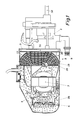
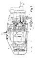
- the high-pressure cleaner shown in the drawing comprises two housing components, i.e.
- the pump comprising the pistons 2 and the cylinders 3 is in the normal manner adapted to receive cleaning liquid through an inlet 9 and to expel this liquid under high pressure through a jet lance 10, of which only the root portion is shown.
- the pump housing 1 is secured to a drive-mechanism housing 11, in the exemplary embodiment shown containing a swash-plate drive mechanism 12 adapted in the normal manner to reciprocate the pistons 2 in a direction parallel to the rotational axis 13 of the drive mechanism 12.
- the drive-mechanism housing 11 surrounds the drive mechanism 12 substantially coaxially to the axis 13 and comprises an annular-section flow space 14 constituting the liquid-flow part of the air cooler 8.
- the flow space 14 communicates with the inlet 9 receiving cleaning liquid from a suitable source (not shown), and at its uppermost point 16, it communicates with the inlet conduit 17 of the pump housing 1.
- the annular-section flow space 14 constitutes the liquid-flow part of the air cooler 8.
- the air-flow part of this air cooler 8 is constituted by a number of ribs 18, forming between them a number of air channels 19.
- the ribs 18 are integral parts of the radially outer portion of the drive-mechanism housing 11 containing the flow space 14, so that the ribs 18 can conduct heat from air passing through the air channels 19 to the cleaning liquid flowing through the flow space 14.
- the air channels 19 extend more or less parallel to each other through an air-entry portion 20, an intermediate portion 21 and an air-exit portion 22.
- the air-entry portion 20 will receive comparatively hot air from the motor 7, whilst the air-exit portion 22 will deliver cooled air outside of the structure of the motor 7, but within the casing space 23 defined by the casing 4, flowing to the opposite end of the latter, where it is drawn in by the fan 6 and made to flow in circulation through the motor 7, i.g. between the components of the latter, towards the air-entry portion 20 of the air cooler 8.
- the pump housing 1 and the drive-mechanism housing 11 between them enclose a substantially closed mechanism space 24 containing substantial parts of the drive mechanism 12 as well as parts of the pistons 2.
- This mechanism space 24 will normally contain a quantity of lubricating oil (not shown) to lubricate the cooperating parts of the drive mechanism and the pistons.
- the casing space 23 is in direct contact with the radially inner wall of the drive-mechanism housing 11, the lubricating oil and hence the drive mechanism 12 will also be cooled by the cleaning liquid entering the cleaner through the inlet 9 and flowing through the annular-section flow space 14.
- the shaft 25 of the motor 7 extends from both ends of the latter, carrying the fan 6 on the left-hand and the rotating part of the swash-plate drive mechanism 12 on the other.
- the fan 6 is surrounded by a cowling 26 roughly in the form of a collar.
- the air flowing through the air channels 19 flows in substantially the same direction as the cleaning liquid flowing through the liquid-flow part 14, i.e. the air cooler 8 acts as a "co-current" heat exchanger. If heat exchange of the counter-current type is desired, it will be sufficient to reverse merely one of the flows mentioned, e.g. by reversing the liquid conduit connections to the flow space 14, thus making the point 16 the inlet and the point 15 the outlet point.
- a high-pressure cleaner of this type will normally comprise various accessories, such as handles, electrical switches etc., but as these components are not affected by the present invention, they have not been described.
Landscapes
- Details Of Reciprocating Pumps (AREA)
- Structures Of Non-Positive Displacement Pumps (AREA)
- Organic Low-Molecular-Weight Compounds And Preparation Thereof (AREA)
- Treating Waste Gases (AREA)
Priority Applications (5)
| Application Number | Priority Date | Filing Date | Title |
|---|---|---|---|
| EP91121016A EP0546202B1 (fr) | 1991-12-07 | 1991-12-07 | Nettoyeur haute pression avec moteur refroidi par air |
| DE69105142T DE69105142T2 (de) | 1991-12-07 | 1991-12-07 | Hochdruckreiniger mit luftgekühltem Motor. |
| DK91121016.9T DK0546202T3 (da) | 1991-12-07 | 1991-12-07 | Højtryksrenser med luftkølet motor |
| AT91121016T ATE113871T1 (de) | 1991-12-07 | 1991-12-07 | Hochdruckreiniger mit luftgekühltem motor. |
| US08/170,670 US5338162A (en) | 1991-12-07 | 1993-12-20 | High-pressure cleaner with air-cooled motor |
Applications Claiming Priority (1)
| Application Number | Priority Date | Filing Date | Title |
|---|---|---|---|
| EP91121016A EP0546202B1 (fr) | 1991-12-07 | 1991-12-07 | Nettoyeur haute pression avec moteur refroidi par air |
Publications (2)
| Publication Number | Publication Date |
|---|---|
| EP0546202A1 true EP0546202A1 (fr) | 1993-06-16 |
| EP0546202B1 EP0546202B1 (fr) | 1994-11-09 |
Family
ID=8207411
Family Applications (1)
| Application Number | Title | Priority Date | Filing Date |
|---|---|---|---|
| EP91121016A Expired - Lifetime EP0546202B1 (fr) | 1991-12-07 | 1991-12-07 | Nettoyeur haute pression avec moteur refroidi par air |
Country Status (5)
| Country | Link |
|---|---|
| US (1) | US5338162A (fr) |
| EP (1) | EP0546202B1 (fr) |
| AT (1) | ATE113871T1 (fr) |
| DE (1) | DE69105142T2 (fr) |
| DK (1) | DK0546202T3 (fr) |
Cited By (2)
| Publication number | Priority date | Publication date | Assignee | Title |
|---|---|---|---|---|
| DE19860751A1 (de) * | 1998-12-23 | 2000-07-06 | Frg Oberflaechenbechandlung Gm | Hochdruckstrahl-Anlage |
| WO2020220504A1 (fr) * | 2019-04-29 | 2020-11-05 | 江苏苏美达五金工具有限公司 | Groupe motopompe pour machine à laver à haute pression portative et machine à laver à haute pression portative |
Families Citing this family (14)
| Publication number | Priority date | Publication date | Assignee | Title |
|---|---|---|---|---|
| US5700137A (en) * | 1995-07-28 | 1997-12-23 | Gp Companies, Inc. | Low profile positive displacement pump system |
| US5556264A (en) * | 1995-07-28 | 1996-09-17 | Gp Companies, Inc. | Low profile positive displacement pump system |
| US5784755A (en) * | 1996-01-18 | 1998-07-28 | White Consolidated Industries, Inc. | Wet extractor system |
| DE29616143U1 (de) * | 1996-09-18 | 1998-01-22 | Suttner Gmbh & Co Kg, 33689 Bielefeld | Hochdruckreinigungsgerät mit einem Verbrennungs-Antriebsmotor |
| US5930852A (en) * | 1997-03-21 | 1999-08-03 | Aqua-Flo, Incorporated | Heat exchanging pump motor for usage within a recirculating water system |
| DE10340744B4 (de) * | 2003-08-29 | 2012-03-29 | Alfred Kärcher Gmbh & Co. Kg | Hochdruckreinigungsgerät |
| US20050186091A1 (en) * | 2004-02-09 | 2005-08-25 | Ghassem Zarbi | Cooling fan mechanism for a motor-driven pressure washer |
| US8444068B2 (en) | 2005-10-26 | 2013-05-21 | Techtronic Outdoor Products Technology Limited | Dual flow pressure washer |
| US7854398B2 (en) * | 2005-10-26 | 2010-12-21 | Techtronic Outdoor Products Technology Limited | Hand held pressure washer |
| US8425203B2 (en) * | 2008-04-25 | 2013-04-23 | Techtronic Outdoor Products Technology Limited | Portable pressure washer system |
| US8337172B2 (en) * | 2009-10-05 | 2012-12-25 | Briggs & Stratton Corporation | Pressure washer pump and engine system |
| US8408882B2 (en) * | 2009-10-05 | 2013-04-02 | Briggs & Stratton Corporation | Pressure washer pump and engine system |
| US8794209B2 (en) | 2010-11-18 | 2014-08-05 | Briggs & Stratton Corporation | Engine mounting system |
| DE102015117079A1 (de) * | 2015-10-07 | 2017-04-13 | Alfred Kärcher Gmbh & Co. Kg | Luftgekühltes Hochdruckreinigungsgerät |
Citations (3)
| Publication number | Priority date | Publication date | Assignee | Title |
|---|---|---|---|---|
| DE3047493A1 (de) * | 1980-12-17 | 1982-07-01 | Alfred Kärcher GmbH & Co, 7057 Winnenden | "hochdruckreinigungsgeraet" |
| FR2504206A1 (fr) * | 1981-04-18 | 1982-10-22 | Kaercher Gmbh & Co Alfred | Groupe motopompe pour un appareil de nettoyage haute pression |
| EP0420473A1 (fr) * | 1989-09-23 | 1991-04-03 | Black & Decker Inc. | Appareil de nettoyage haute pression de main |
Family Cites Families (4)
| Publication number | Priority date | Publication date | Assignee | Title |
|---|---|---|---|---|
| US2787720A (en) * | 1955-04-26 | 1957-04-02 | Allis Louis Co | Cooling of electric machines |
| US4125345A (en) * | 1974-09-20 | 1978-11-14 | Hitachi, Ltd. | Turbo-fluid device |
| DK140453C (da) * | 1974-12-21 | 1980-01-28 | Vorwerk Co Interholding | Stoevsuger |
| US4802826A (en) * | 1982-06-25 | 1989-02-07 | Rix Industries | Sealed, self-contained, liquid-cooled, gas compressor |
-
1991
- 1991-12-07 DE DE69105142T patent/DE69105142T2/de not_active Expired - Fee Related
- 1991-12-07 DK DK91121016.9T patent/DK0546202T3/da active
- 1991-12-07 EP EP91121016A patent/EP0546202B1/fr not_active Expired - Lifetime
- 1991-12-07 AT AT91121016T patent/ATE113871T1/de not_active IP Right Cessation
-
1993
- 1993-12-20 US US08/170,670 patent/US5338162A/en not_active Expired - Fee Related
Patent Citations (3)
| Publication number | Priority date | Publication date | Assignee | Title |
|---|---|---|---|---|
| DE3047493A1 (de) * | 1980-12-17 | 1982-07-01 | Alfred Kärcher GmbH & Co, 7057 Winnenden | "hochdruckreinigungsgeraet" |
| FR2504206A1 (fr) * | 1981-04-18 | 1982-10-22 | Kaercher Gmbh & Co Alfred | Groupe motopompe pour un appareil de nettoyage haute pression |
| EP0420473A1 (fr) * | 1989-09-23 | 1991-04-03 | Black & Decker Inc. | Appareil de nettoyage haute pression de main |
Cited By (2)
| Publication number | Priority date | Publication date | Assignee | Title |
|---|---|---|---|---|
| DE19860751A1 (de) * | 1998-12-23 | 2000-07-06 | Frg Oberflaechenbechandlung Gm | Hochdruckstrahl-Anlage |
| WO2020220504A1 (fr) * | 2019-04-29 | 2020-11-05 | 江苏苏美达五金工具有限公司 | Groupe motopompe pour machine à laver à haute pression portative et machine à laver à haute pression portative |
Also Published As
| Publication number | Publication date |
|---|---|
| EP0546202B1 (fr) | 1994-11-09 |
| DK0546202T3 (da) | 1995-04-18 |
| US5338162A (en) | 1994-08-16 |
| DE69105142D1 (de) | 1994-12-15 |
| DE69105142T2 (de) | 1995-03-23 |
| ATE113871T1 (de) | 1994-11-15 |
Similar Documents
| Publication | Publication Date | Title |
|---|---|---|
| EP0546202B1 (fr) | Nettoyeur haute pression avec moteur refroidi par air | |
| US5509381A (en) | Method of and means for cooling and lubricating an alternator | |
| US6408937B1 (en) | Active cold plate/heat sink | |
| US3525001A (en) | Liquid cooled electric motor | |
| KR101888156B1 (ko) | 분리된 냉각 기로를 구비한 터보 압축기 | |
| US4110643A (en) | Induction motor | |
| US3163790A (en) | Motor driven pumps | |
| SE466666B (sv) | Radialkolvpump | |
| CN114793040B (zh) | 用于电动机内部结构的双重辅助冷却机构 | |
| US8096782B2 (en) | Multistage sealed coolant pump | |
| JP2000110768A (ja) | 水中ポンプモ―タのための閉ル―プ強制冷却装置 | |
| CA2456559A1 (fr) | Unites de propulsion electrique | |
| US11445634B2 (en) | Water pump for water cooler for electronic component | |
| EP1920523A1 (fr) | Système de refroidissement d'un ensemble global | |
| KR100892530B1 (ko) | 스크류 냉각식 진공 펌프 | |
| US20230387751A1 (en) | Centrifugal Pump With a Drive | |
| US20210172368A1 (en) | Integrated hybrid power apparatus | |
| US6419460B1 (en) | Driving mechanism for a pump | |
| US4247266A (en) | Fluid pump drive system | |
| WO1993018303A1 (fr) | Pompe entrainee par un moteur electrique immerge | |
| GB2185551A (en) | A power transmission system | |
| US3176913A (en) | Rotary compressor arrangement | |
| US11837943B2 (en) | Rotor air cooling system | |
| DE102014016481A1 (de) | Elektromotorische Wasserpumpe | |
| KR100424795B1 (ko) | 자체순환 냉각시스템 진공펌프 |
Legal Events
| Date | Code | Title | Description |
|---|---|---|---|
| PUAI | Public reference made under article 153(3) epc to a published international application that has entered the european phase |
Free format text: ORIGINAL CODE: 0009012 |
|
| 17P | Request for examination filed |
Effective date: 19921010 |
|
| AK | Designated contracting states |
Kind code of ref document: A1 Designated state(s): AT BE CH DE DK ES FR GB GR IT LI LU NL SE |
|
| 17Q | First examination report despatched |
Effective date: 19940315 |
|
| GRAA | (expected) grant |
Free format text: ORIGINAL CODE: 0009210 |
|
| AK | Designated contracting states |
Kind code of ref document: B1 Designated state(s): AT BE CH DE DK ES FR GB GR IT LI LU NL SE |
|
| PG25 | Lapsed in a contracting state [announced via postgrant information from national office to epo] |
Ref country code: NL Effective date: 19941109 Ref country code: LI Effective date: 19941109 Ref country code: GR Free format text: LAPSE BECAUSE OF FAILURE TO SUBMIT A TRANSLATION OF THE DESCRIPTION OR TO PAY THE FEE WITHIN THE PRESCRIBED TIME-LIMIT Effective date: 19941109 Ref country code: FR Effective date: 19941109 Ref country code: ES Free format text: THE PATENT HAS BEEN ANNULLED BY A DECISION OF A NATIONAL AUTHORITY Effective date: 19941109 Ref country code: CH Effective date: 19941109 Ref country code: BE Effective date: 19941109 Ref country code: AT Effective date: 19941109 |
|
| REF | Corresponds to: |
Ref document number: 113871 Country of ref document: AT Date of ref document: 19941115 Kind code of ref document: T |
|
| ITF | It: translation for a ep patent filed | ||
| REF | Corresponds to: |
Ref document number: 69105142 Country of ref document: DE Date of ref document: 19941215 |
|
| PG25 | Lapsed in a contracting state [announced via postgrant information from national office to epo] |
Ref country code: LU Free format text: LAPSE BECAUSE OF NON-PAYMENT OF DUE FEES Effective date: 19941231 |
|
| PG25 | Lapsed in a contracting state [announced via postgrant information from national office to epo] |
Ref country code: SE Effective date: 19950209 |
|
| REG | Reference to a national code |
Ref country code: CH Ref legal event code: PL |
|
| EN | Fr: translation not filed | ||
| NLV1 | Nl: lapsed or annulled due to failure to fulfill the requirements of art. 29p and 29m of the patents act | ||
| REG | Reference to a national code |
Ref country code: DK Ref legal event code: T3 |
|
| PLBE | No opposition filed within time limit |
Free format text: ORIGINAL CODE: 0009261 |
|
| STAA | Information on the status of an ep patent application or granted ep patent |
Free format text: STATUS: NO OPPOSITION FILED WITHIN TIME LIMIT |
|
| 26N | No opposition filed | ||
| PG25 | Lapsed in a contracting state [announced via postgrant information from national office to epo] |
Ref country code: GB Effective date: 19951207 |
|
| GBPC | Gb: european patent ceased through non-payment of renewal fee |
Effective date: 19951207 |
|
| PGFP | Annual fee paid to national office [announced via postgrant information from national office to epo] |
Ref country code: DK Payment date: 19961223 Year of fee payment: 6 |
|
| PG25 | Lapsed in a contracting state [announced via postgrant information from national office to epo] |
Ref country code: DK Free format text: LAPSE BECAUSE OF NON-PAYMENT OF DUE FEES Effective date: 19971207 |
|
| PGFP | Annual fee paid to national office [announced via postgrant information from national office to epo] |
Ref country code: DE Payment date: 20010125 Year of fee payment: 10 |
|
| REG | Reference to a national code |
Ref country code: DK Ref legal event code: EBP |
|
| PG25 | Lapsed in a contracting state [announced via postgrant information from national office to epo] |
Ref country code: DE Free format text: LAPSE BECAUSE OF NON-PAYMENT OF DUE FEES Effective date: 20020702 |
|
| PG25 | Lapsed in a contracting state [announced via postgrant information from national office to epo] |
Ref country code: IT Free format text: LAPSE BECAUSE OF NON-PAYMENT OF DUE FEES;WARNING: LAPSES OF ITALIAN PATENTS WITH EFFECTIVE DATE BEFORE 2007 MAY HAVE OCCURRED AT ANY TIME BEFORE 2007. THE CORRECT EFFECTIVE DATE MAY BE DIFFERENT FROM THE ONE RECORDED. Effective date: 20051207 |