EP0545086B1 - Permanent shuttering element - Google Patents
Permanent shuttering element Download PDFInfo
- Publication number
- EP0545086B1 EP0545086B1 EP92118853A EP92118853A EP0545086B1 EP 0545086 B1 EP0545086 B1 EP 0545086B1 EP 92118853 A EP92118853 A EP 92118853A EP 92118853 A EP92118853 A EP 92118853A EP 0545086 B1 EP0545086 B1 EP 0545086B1
- Authority
- EP
- European Patent Office
- Prior art keywords
- sleeves
- shuttering element
- nail
- shuttering
- element according
- Prior art date
- Legal status (The legal status is an assumption and is not a legal conclusion. Google has not performed a legal analysis and makes no representation as to the accuracy of the status listed.)
- Expired - Lifetime
Links
Images


Classifications
-
- E—FIXED CONSTRUCTIONS
- E04—BUILDING
- E04G—SCAFFOLDING; FORMS; SHUTTERING; BUILDING IMPLEMENTS OR AIDS, OR THEIR USE; HANDLING BUILDING MATERIALS ON THE SITE; REPAIRING, BREAKING-UP OR OTHER WORK ON EXISTING BUILDINGS
- E04G15/00—Forms or shutterings for making openings, cavities, slits, or channels
- E04G15/06—Forms or shutterings for making openings, cavities, slits, or channels for cavities or channels in walls of floors, e.g. for making chimneys
- E04G15/061—Non-reusable forms
Definitions
- the invention relates to a lost formwork element, in particular a recess body made of a hardenable material such as concrete, which is to be fastened to a formwork panel by nails.
- Formwork elements of this type are known in a wide variety of types and shapes. In order to withstand the pressure of the poured concrete, they must be attached to the formwork board carrying them, which is generally done by nailing. The formwork elements mostly consist of wood.
- CH-A-579 196 discloses a recess connector in which the holding force between the lost formwork element and the nail can be less than between the nail and the formwork panel.
- this publication does not disclose what is the reason for these different holding forces.
- the recessed connector has protruding sleeves on its area adjacent to the formwork panel, the bores of which are directed towards the formwork panel and are used in each case to receive a nail.
- the nails should be able to be torn away together with the formwork panel after the concrete has solidified.
- US-A-3 157 966 corresponding holding force ratios, which allow the nails to be pulled off together with the formwork panel, are known, which is due to a special design of the nail head is achieved. The hitherto necessary pinching, flat tapping and similar measures to remove the nail projecting downward are thus unnecessary. Above all, however, the nail stump in the concrete, which is a latent source of corrosion, has been eliminated.
- the object of the present invention is to improve the formwork elements formed in such a way that further possible sources of corrosion are eliminated.
- This object is achieved in that the sleeves used for nail fastening are closed at their lower ends with thin walls. This also eliminates the nails, which are not required for fastening the formwork element, as a source of corrosion by reliably isolating the nail tips from the concrete and thus preventing them from rusting.
- the sleeves can be integrated directly into the wall of the formwork element and only protrude slightly above, so that the formwork element cannot be damaged too easily when hammering. Likewise, the sleeves can also be connected as separate parts to the formwork element, for example by a snap or clamp connection.
- the sleeves In order to make hammering in the nails easier, it is advisable not to arrange the sleeves inside but outside the formwork element, i.e. on the side exposed to the concrete to be filled.
- the formwork elements expediently have directly formed side projections on this side, in which the sleeves are inserted.
- the formwork element itself can consist of mortar, in particular fiber-reinforced mortar, other concrete-like materials, but also of bound wood wool or plastic.
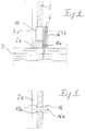
- FIG. 1 shows two formwork elements 1 and 2, which are combined with further, not shown formwork elements to form a lost recess body in order to avoid a continuous opening in a concrete ceiling.
- the formwork elements are equipped on their lower, outer edge with a plurality of projections 3, 4, in each of which a nail 5 or 6 is seated. The details of these projections will be discussed later with reference to FIGS. 4 to 9.
- the formwork elements are then nailed onto a conventional wooden formwork panel 7, on which the concrete is later poured.
- the formwork elements form a rectangle, the adjoining side wall parts of which lie against one another in liquid-tight concrete or are inserted into one another. This state is shown in Fig. 2.
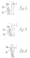
- the projections 4 are formed by separate plastic sleeves 16, which are anchored to the formwork element 2 via extensions 17.
- the extensions 17 can be cast directly into the wall of the formwork element, but they can, like in the exemplary embodiment shown, be resiliently latched into openings in the formwork elements by lateral projections 17a.
- the plastic sleeves 16 On the outside, the plastic sleeves 16 have an approximately vertically running bore 16a. This bore 16a serves to receive the nail 6.
- the nail 6 is expediently held in the bore 16a by friction so that it cannot slip out during transport and assembly.
- the nail 6 is held in the driven-in state only with a frictional force which is less than the holding force between the nail 6 and the lower formwork panel 7.
- This can be done by appropriate dimensional adjustment between the plastic sleeve 16 and the nail 6, as well but also by providing predetermined breaking points that lie below the nail head when the nail is driven in and break out of the plastic sleeve 16 at a lower force than is necessary for pulling the nail out of the lower formwork panel 7.
- FIGS. 6 and 7 show alternatives in which an approximately cylindrical plastic sleeve 26 is used and this plastic sleeve is integrated directly into the wall material of the formwork element.
- the formwork element according to FIGS. 6 and 7 has on its lower edge an outwardly projecting projection 2a which functions as a carrier for the inserted sleeve 26.
- the sleeve 26 can be perpendicular or slightly inclined outwards and arranged with or without an upper protrusion in the projection 2a.
- 9a to 9c show configurations of the plastic sleeve 16, by means of which concrete milk is prevented from penetrating into the bore 16a and making it difficult to pull the nail or leading to its corrosion.
- the sleeve 16 is provided at the upper end of the bore 16a with inwardly projecting sealing lips 16c, which bear against the head when the nail 6 is driven in and thus seal the bore 16a upward.
- the bore 16a can also be closed at its lower end by a membrane 16d.
- a membrane 16d prevents the penetration of concrete milk to the tip of the nail and corrosion resulting therefrom.
- the membrane 16d is dimensioned such that, on the other hand, it can be easily pierced when the nail is hammered in.
- FIGS. 9a and 9b finally shows a horizontal section through an alternative embodiment of the bore 16a.
- it is provided with a plurality of vertically extending ribs 16e which rest against the shaft of the nail and ensure the desired friction conditions.
- This embodiment is particularly recommended for nails with a small head or without a head, the plastic sleeve, as in FIGS. 9a and 9b, preferably remaining on the formwork element when the nail is pulled.
- nail used above includes all possible nailable fastening pins, in particular also those without a head and those with special external profiling on the circumference of the shaft.
Abstract
Description
Die Erfindung betrifft ein verlorenes Schalungselement, insbesondere Aussparungskörper aus einem aushärtbarem Material wie Beton, das durch Nägel an einer Schaltafel zu befestigen ist.The invention relates to a lost formwork element, in particular a recess body made of a hardenable material such as concrete, which is to be fastened to a formwork panel by nails.
Derartige Schalungselemente sind in den unterschiedlichsten Arten und Formen bekannt. Um dem Druck des eingefüllten Betons standzuhalten, müssen sie an der sie tragenden Schaltafel befestigt werden, was im allgemeinen durch Nageln erfolgt. Die Schalungselemente bestehen dabei meist aus Holz.Formwork elements of this type are known in a wide variety of types and shapes. In order to withstand the pressure of the poured concrete, they must be attached to the formwork board carrying them, which is generally done by nailing. The formwork elements mostly consist of wood.
Beispielsweise offenbart die CH-A-579 196 einen Aussparungsstutzen, bei dem die Haltekraft zwischen verlorenem Schalungselement und Nagel geringer sein kann als zwischen Nagel und Schaltafel. Allerdings wird in dieser Druckschrift nicht offenbart, was der Grund für diese unterschiedlichen Haltekräfte ist. Jedenfalls weist der Aussparungsstutzen an seinem an der Schaltafel angrenzenden Bereich vorstehende Hülsen auf, deren auf die Schaltafel gerichtete Bohrungen jeweils zur Aufnahme eines Nagels dienen. Auf diese Weise sollen die Nägel nach dem Erstarren des Betons zusammen mit der Schaltafel weggerissen werden können. Auch aus der US-A-3 157 966 sind entsprechende, ein Abziehen der Nägel zusammen mit der Schaltafel ermöglichende Halte-Kraftverhältnisse bekannt, was dort durch eine besondere Ausgestaltung des Nagelkopfes erreicht wird. Das bisher notwendige Abzwicken, Flachklopfen und ähnliche Maßnahmen zur Beseitigung des nach unten vorstehenden Nagels erübrigen sich dadurch. Vor allem aber ist auch der im Beton sitzende Nagelstumpf, der eine latente Korrosionsquelle darstellt, eliminiert.For example, CH-A-579 196 discloses a recess connector in which the holding force between the lost formwork element and the nail can be less than between the nail and the formwork panel. However, this publication does not disclose what is the reason for these different holding forces. In any case, the recessed connector has protruding sleeves on its area adjacent to the formwork panel, the bores of which are directed towards the formwork panel and are used in each case to receive a nail. In this way, the nails should be able to be torn away together with the formwork panel after the concrete has solidified. From US-A-3 157 966, corresponding holding force ratios, which allow the nails to be pulled off together with the formwork panel, are known, which is due to a special design of the nail head is achieved. The hitherto necessary pinching, flat tapping and similar measures to remove the nail projecting downward are thus unnecessary. Above all, however, the nail stump in the concrete, which is a latent source of corrosion, has been eliminated.
Hiervon ausgehend liegt der vorliegenden Erfindung die Aufgabe zugrunde, die gebildeten Schalungselemente dahingehend zu verbessern, daß weitere mögliche Korrosionsquellen beseitigt werden.Proceeding from this, the object of the present invention is to improve the formwork elements formed in such a way that further possible sources of corrosion are eliminated.
Diese Aufgabe wird erfindungsgemäß dadurch gelöst, daß die zur Nagelbefestigung dienenden Hülsen an ihrem unteren Ende dünnwandig verschlossen sind. Dadurch werden auch die Nägel, die nicht zur Befestigung des Schalungselementes benötigt werden, als Korrosionsquelle eliminiert, indem die Nagelspitzen zuverlässig gegenüber dem Beton isoliert sind und somit nicht zu rosten anfangen können.This object is achieved in that the sleeves used for nail fastening are closed at their lower ends with thin walls. This also eliminates the nails, which are not required for fastening the formwork element, as a source of corrosion by reliably isolating the nail tips from the concrete and thus preventing them from rusting.
Grundsätzlich liegt es im Rahmen der Erfindung, die Hülsen erst auf der Baustelle mit Nägeln zu bestücken. Um jedoch die gewünschten Reibungsverhältnisse mit Sicherheit einzuhalten, empfiehlt es sich, die Hülsen bereits herstellerseitig mit den richtigen Nägeln zu füllen.Basically, it is within the scope of the invention to equip the sleeves with nails only at the construction site. However, to ensure that the desired friction conditions are maintained, it is advisable to fill the sleeves with the right nails from the manufacturer.
Hinsichtlich des Abziehens der Nägel vom Schalungselement bestehen im wesentlichen zwei Möglichkeiten: Entweder werden die Nägel durch die am Schalungselement verbleibenden Hülsen hindurchgezogen oder sie werden mitsamt ihren Hülsen vom Schalungselement gelöst. In beiden Fällen empfiehlt es sich, daß die Hülsen aus Kunststoff bestehen, so daß eine gewisse Nachgiebigkeit gewährleistet ist.With regard to the removal of the nails from the formwork element, there are essentially two possibilities: either the nails are pulled through the sleeves remaining on the formwork element or they and their sleeves are detached from the formwork element. In both cases, it is recommended that the sleeves are made of plastic, so that a certain flexibility is guaranteed.
Die Hülsen können unmittelbar in die Wandung des Schalungselementes integriert sein und nur oben etwas vorstehen, damit das Schalungselement beim Hämmern nicht zu leicht beschädigt werden kann. Ebenso können die Hülsen aber auch als separate Teile mit dem Schalungselement verbunden werden, beispielsweise durch eine Schnapp- oder Klemmverbindung.The sleeves can be integrated directly into the wall of the formwork element and only protrude slightly above, so that the formwork element cannot be damaged too easily when hammering. Likewise, the sleeves can also be connected as separate parts to the formwork element, for example by a snap or clamp connection.
Damit das Einhämmern der Nägel erleichtert wird, empfiehlt es sich, die Hülsen nicht innerhalb, sondern außerhalb des Schalungselementes anzuordnen, also an der vom einzufüllenden Beton beaufschlagten Seite. Zweckmäßig weisen die Schalungselemente an dieser Seite unmittelbar angeformte seitliche Vorsprünge auf, in denen die Hülsen stecken.In order to make hammering in the nails easier, it is advisable not to arrange the sleeves inside but outside the formwork element, i.e. on the side exposed to the concrete to be filled. The formwork elements expediently have directly formed side projections on this side, in which the sleeves are inserted.
Das Schalungselement selbst kann aus Mörtel, insbesondere faserverstärktem Mörtel, anderen betonähnlichen Stoffen, aber auch aus gebundener Holzwolle oder Kunststoff bestehen.The formwork element itself can consist of mortar, in particular fiber-reinforced mortar, other concrete-like materials, but also of bound wood wool or plastic.
Weitere Merkmale und Vorteile der Erfindung ergeben sich aus der nachfolgenden Beschreibung von Ausführungsbeispielen anhand der Zeichnung; dabei zeigt
- Fig. 1 - 3
- die Montage des Schalungselementes;
- Fig. 4
- einen vergrößerten Ausschnitt des Befestigungsbereiches im Vertikalschnitt;
- Fig. 5
- einen Horizontalschnitt längs der Linie V-V in Fig. 4;
- Fig. 6 - 8
- vergrößerte Darstellungen des Befestigungsbereiches mit unterschiedlichen Alternativen;
- Fig. 9a - c
- vergrößerte Details der Hülse.
- 1 - 3
- the assembly of the formwork element;
- Fig. 4
- an enlarged section of the fastening area in vertical section;
- Fig. 5
- a horizontal section along the line VV in Fig. 4;
- 6 - 8
- enlarged representations of the fastening area with different alternatives;
- 9a-c
- enlarged details of the sleeve.
In Fig. 1 erkennt man zwei Schalungselemente 1 und 2, die mit weiteren, nicht gezeigten Schalungselementen zu einem verlorenen Aussparungskörper kombiniert werden, um eine durchgehende Öffnung in einer Betondecke auszusparen. Hierzu sind die Schalungselemente an ihrem unteren, außenliegenden Rand mit mehreren Vorsprüngen 3, 4 bestückt, in denen jeweils ein Nagel 5 bzw. 6 sitzt. Auf die nähere Ausbildung dieser Vorsprünge wird später anhand der Fig. 4 bis 9 zurückgekommen.1 shows two
Die Schalungselemente werden sodann auf eine herkömmliche hölzerne Schaltafel 7 aufgenagelt, auf der später der Beton vergossen wird. Dabei bilden die Schalungselemente ein Rechteck, dessen angrenzende Seitenwandteile flüssigbetondicht aneinander liegen oder ineinander gesteckt sind. Dieser Zustand ist in Fig. 2 dargestellt.The formwork elements are then nailed onto a conventional
Nach dem Eingießen und Erstarren der Betondecke 8 wird die untere Schaltafel 7 abgenommen und dabei werden sämtliche Nägel 5, 6 von den Schalungselementen 1, 2 gleich mit abgezogen.After pouring and solidification of the
Die Fig. 4 und 5 verdeutlichen die erfindungsgemäße Nagelhalterung am Schalungselement gemäß einer ersten Alternative. Dabei werden die Vorsprünge 4 durch seperate Kunststoffhülsen 16 gebildet, die über Fortsätze 17 am Schalungselement 2 verankert sind. Die Fortsätze 17 können unmittelbar in die Wand des Schalungselementes eingegossen sein, sie können aber ebenso wie im gezeigten Ausführungsbeispiel durch seitliche Vorsprünge 17a federnd in Öffnungen der Schalungselemente verrastet werden.4 and 5 illustrate the nail holder according to the invention on the formwork element according to a first alternative. The
An der Außenseite weisen die Kunststoffhülsen 16 eine etwa vertikal verlaufende Bohrung 16a auf. Diese Bohrung 16a dient zur Aufnahme des Nagels 6.On the outside, the
Zweckmäßig ist der Nagel 6 in der Bohrung 16a durch Reibung festgehalten, damit er während des Transportes und der Montage nicht herausrutschen kann. Durch entsprechende Bemessung der Bohrung 16a wird der Nagel 6 in eingeschlagenem Zustand nur mit einer solchen Reibungskraft festgehalten, die geringer ist als die Haltekraft zwischen Nagel 6 und unterer Schaltafel 7. Dies kann allein durch entsprechende maßliche Anpassung zwischen Kunststoffhülse 16 und Nagel 6 erfolgen, ebenso aber auch durch Vorsehen von Sollbruchstellen, die bei eingeschlagenem Nagel unterhalb des Nagelkopfes liegen und bei einer geringeren Kraft aus der Kunststoffhülse 16 ausbrechen als zum Ziehen des Nagels aus der unteren Schaltafel 7 notwendig ist.The
Die Fig. 6 bis 8 zeigen Alternativen, bei denen mit einer etwa zylindrischen Kunststoffhülse 26 gearbeitet wird und diese Kunststoffhülse unmittelbar in das Wandmaterial des Schalungselementes integriert ist. Dazu weist das Schalungselement gemäß Fig. 6 und 7 an seinem unteren Rand eine nach außen ragenden Vorsprung 2a auf, der als Träger für die eingesteckte Hülse 26 fungiert. Die Hülse 26 kann dabei lotrecht oder auch leicht nach außen geneigt und mit oder ohne oberen Überstand im Vorsprung 2a angeordnet sein.6 to 8 show alternatives in which an approximately cylindrical
In Fig. 8 ist auf den genannten Vorsprung verzichtet worden und die Hülse 26 stattdessen direkt schräg in das Schalungselement integriert.In Fig. 8, the aforementioned projection has been dispensed with and the
Allen Varianten nach Fig. 6 bis 8 ist gemeinsam, daß die Hülse 26 bei Entfernen der unteren Schaltafel 7 und dem damit einhergehenden Abziehen der Nägel entweder am Schalungselement verbleiben oder aber zusammen mit dem Nagel aus dem Schalungselement herausgezogen werden kann. Im ersten Fall liegen die bereits weiter oben beschriebenen Reibungsverhältnisse vor. Im zweiten Fall wird die Haltekraft zwischen Kunststoffhülse 26 und Nagel höher gewählt als die Haltekraft zwischen Nagel und Schaltafel 7; dafür muß die Haltekraft zwischen Kunststoffhülse 26 und dem Schalungselement geringer sein als zwischen Nagel und Schaltafel.All variants according to FIGS. 6 to 8 have in common that the
Die Fig. 9a bis 9c zeigen Ausgestaltungen der Kunststoffhülse 16, durch die verhindert wird, daß Betonmilch in die Bohrung 16a eindringt und das Ziehen des Nagels erschwert oder zu dessen Korrosion führt.9a to 9c show configurations of the
Hierzu ist die Hülse 16 am oberen Ende der Bohrung 16a mit nach innen ragenden Dichtungslippen 16c versehen, die sich bei eingeschlagenem Nagel 6 an dessen Kopf anlegen und damit die Bohrung 16a nach oben abdichten.For this purpose, the
In Fig. 9b erkennt man, daß die Bohrung 16a auch an ihrem unteren Ende durch eine Membran 16d verschlossen sein kann. Dies empfiehlt sich vor allem dann, wenn damit zu rechnen ist, daß nicht alle Nägel 6 in die Schaltafel eingeschlagen werden und somit auch nach Entfernung der Schaltafel im Beton verbleiben. In diesem Fall verhindert die Membran 16d das Vordringen von Betonmilch zur Nagelspitze und eine hiervon ausgehende Korrosion. Die Membran 16d ist so bemessen, daß sie andererseits beim Einhämmern des Nagels leicht durchstoßen werden kann.9b that the
Fig. 9c schließlich zeigt einen Horizontalschnitt durch eine alternative Ausbildung der Bohrung 16a. Sie ist in diesem Fall mit mehreren vertikal verlaufenden Rippen 16e versehen, die sich an den Schaft des Nagels anlegen und für die gewünschten Reibungsverhältnisse sorgen. Diese Ausführungsform empfiehlt sich insbesondere für Nägel mit kleinem Kopf oder ohne Kopf, wobei die Kunststoffhülse ebenso wie bei Fig. 9a und 9b vorzugsweise beim Ziehen des Nagels am Schalungselement verbleibt.9c finally shows a horizontal section through an alternative embodiment of the
Selbstverständlich umfaßt der vorstehend verwendete Begriff "Nagel" alle möglichen nagelbaren Befestigungsstifte, insbesondere also auch solche ohne Kopf und solche mit spezieller Außenprofilierung am Schaftumfang.Of course, the term "nail" used above includes all possible nailable fastening pins, in particular also those without a head and those with special external profiling on the circumference of the shaft.
Claims (10)
- A lost shuttering element (1,2), in particular for formwork of a hardenable material like concrete, which is fastened by nails (5,6) to a shutter board (7), whereby the retention force between the lost shuttering (1,2) and a nail (5,6) is less than that between said nail (5,6) and a board (7), for which purpose the lost shuttering element (1,2) has projecting sleeves (3, 4, 16, 26) where it abuts against the shutter board (7), and drill-holes (16a, 26a) of the sleeves, which point towards the board, each arranged to accomodate a nail (6), characterised in that the sleeves (16) terminate in a thin wall (16d).
- A shuttering element according to Claim 1, characterised in that the sleeves (3, 4, 16, 26) each hold a nail (6) firmly braced.
- A shuttering element according to Claim 1, characterised in that when the shutter board is removed the nails can be withdrawn through the sleeves (3, 4, 16) retained by the shuttering element (1,2).
- A shuttering element according to Claim 1, characterised in that when the shutter board (7) is removed the nails can be withdrawn from the shuttering element together with their sleeves (26).
- A shuttering element according to Claim 1, characterised in that the sleeves (3, 4, 16, 26) are of plastic.
- A shuttering element according to Claim 1, characterised in that the sleeves (6) are integrated into the shuttering material.
- A shuttering element according to Claim 1, characterised in that, that the sleeves (26) project upwards out of the shuttering material.
- A shuttering element according to Claim 1, characterised in that the sleeves (3, 4, 16) can be connected as separate items to the shuttering element, and in particular can be clipped to it.
- A shuttering element according to Claim 1, characterised in that the sleeves (3, 4, 16, 26) are accommodated on the side of the shuttering element on to which the concrete is poured.
- A shuttering element according to Claim 1, characterised in that the sleeves (26) are accommodated in lateral projections (2a) from the shuttering element (2).
Applications Claiming Priority (2)
| Application Number | Priority Date | Filing Date | Title |
|---|---|---|---|
| DE4140074 | 1991-12-05 | ||
| DE4140074A DE4140074A1 (en) | 1991-12-05 | 1991-12-05 | LOST FORMWORK ELEMENT |
Publications (2)
| Publication Number | Publication Date |
|---|---|
| EP0545086A1 EP0545086A1 (en) | 1993-06-09 |
| EP0545086B1 true EP0545086B1 (en) | 1996-08-14 |
Family
ID=6446313
Family Applications (1)
| Application Number | Title | Priority Date | Filing Date |
|---|---|---|---|
| EP92118853A Expired - Lifetime EP0545086B1 (en) | 1991-12-05 | 1992-11-04 | Permanent shuttering element |
Country Status (3)
| Country | Link |
|---|---|
| EP (1) | EP0545086B1 (en) |
| AT (1) | ATE141374T1 (en) |
| DE (2) | DE4140074A1 (en) |
Families Citing this family (2)
| Publication number | Priority date | Publication date | Assignee | Title |
|---|---|---|---|---|
| FR2715959B1 (en) * | 1994-02-04 | 1996-04-26 | Jalmat | Support beam for formwork panels and formwork structure comprising such beams. |
| GB2356888B (en) * | 1999-11-24 | 2003-10-29 | Anthire Ltd | Former element |
Family Cites Families (7)
| Publication number | Priority date | Publication date | Assignee | Title |
|---|---|---|---|---|
| US3157966A (en) * | 1961-07-10 | 1964-11-24 | Grinnell Corp | Concrete insert |
| DE2400109A1 (en) * | 1974-01-03 | 1975-07-17 | Liou | Concrete form anchor bolt accommodation unit - with threaded aperture and threaded bolt with protruding nail for removal after concreting |
| CH579196A5 (en) * | 1974-10-09 | 1976-08-31 | Fawa | Recessed connection for pipes in concrete walls - is straight conical short piece of pipe sealed by membrane at one end |
| NL170880C (en) * | 1977-05-18 | 1983-01-03 | Wilma Bv | LOST SAVINGS ELEMENT FOR SAVING A TRANSIT HOLE IN CONCRETE FLOOR. |
| DE3219265C1 (en) * | 1982-05-21 | 1983-10-20 | Friedrich 7024 Filderstadt Manz | Shuttering for the production of clearances and through-passages in concrete structural parts |
| GB2134582B (en) * | 1983-02-01 | 1986-03-12 | Bicc Plc | A method of installing channelling in concrete |
| GB9009374D0 (en) * | 1990-04-26 | 1990-06-20 | Wincro Metal Ind Ltd | Fixing of cast-in channels for facade support and restraint apparatus |
-
1991
- 1991-12-05 DE DE4140074A patent/DE4140074A1/en not_active Withdrawn
-
1992
- 1992-11-04 EP EP92118853A patent/EP0545086B1/en not_active Expired - Lifetime
- 1992-11-04 AT AT92118853T patent/ATE141374T1/en active
- 1992-11-04 DE DE59206913T patent/DE59206913D1/en not_active Expired - Fee Related
Also Published As
| Publication number | Publication date |
|---|---|
| EP0545086A1 (en) | 1993-06-09 |
| DE59206913D1 (en) | 1996-09-19 |
| DE4140074A1 (en) | 1993-06-09 |
| ATE141374T1 (en) | 1996-08-15 |
Similar Documents
| Publication | Publication Date | Title |
|---|---|---|
| CH674864A5 (en) | ||
| DE1801457C3 (en) | Device for lifting and transporting precast concrete parts or the like | |
| EP0055321A1 (en) | Connecting rods holding means for the realization of an efficient bond between two building elements | |
| EP0819203B1 (en) | Support device for at least one elastically deformable securing element and a process for section-concreting using elastically deformable securing elements as a concrete connection | |
| EP2233753A2 (en) | Connection device and process for generating a connection | |
| EP1063434A2 (en) | Wall anchor for reinforcing and/or securing walls | |
| EP1048856B1 (en) | Element for fastening insulating elements | |
| EP0545086B1 (en) | Permanent shuttering element | |
| DE3046290C2 (en) | ||
| EP2444562B1 (en) | Safety area | |
| EP0056255A1 (en) | Device for fixing objects to a concrete wall | |
| EP0077877B1 (en) | Anchorage for step irons in concrete elements or the like | |
| EP0502302B1 (en) | Plastic facing anchor | |
| EP3696338A1 (en) | Connecting element for connecting a shuttering panel to a further structural unit, shuttering unit with connecting element, connection unit with connecting element, parts set for constructing shuttering and shuttering for forming a cast concrete element | |
| EP3611307B1 (en) | Rail system | |
| EP0034346A1 (en) | Fastening set for fastening panels, strips or like construction parts to a wall by means of a synthetic clamping-head dowel | |
| DE3515137A1 (en) | Reception sleeve for fastening elements | |
| DE3632703A1 (en) | Joint-shuttering element | |
| EP0701068A1 (en) | Insulation anchor dowell | |
| DE7730164U1 (en) | ||
| EP3693521A1 (en) | Mounting pin for an anchoring device and method for drawing off mounting pins | |
| EP0094404A1 (en) | Anchoring device for works effected on a concrete wall or ceiling | |
| DE3218376C2 (en) | ||
| DE19758269A1 (en) | Device for positive engagement/forced locking between adjacent component parts | |
| EP0300210A1 (en) | Tube support |
Legal Events
| Date | Code | Title | Description |
|---|---|---|---|
| PUAI | Public reference made under article 153(3) epc to a published international application that has entered the european phase |
Free format text: ORIGINAL CODE: 0009012 |
|
| AK | Designated contracting states |
Kind code of ref document: A1 Designated state(s): AT BE CH DE FR IT LI NL |
|
| 17P | Request for examination filed |
Effective date: 19930621 |
|
| 17Q | First examination report despatched |
Effective date: 19950303 |
|
| GRAH | Despatch of communication of intention to grant a patent |
Free format text: ORIGINAL CODE: EPIDOS IGRA |
|
| GRAH | Despatch of communication of intention to grant a patent |
Free format text: ORIGINAL CODE: EPIDOS IGRA |
|
| GRAA | (expected) grant |
Free format text: ORIGINAL CODE: 0009210 |
|
| AK | Designated contracting states |
Kind code of ref document: B1 Designated state(s): AT BE CH DE FR IT LI NL |
|
| PG25 | Lapsed in a contracting state [announced via postgrant information from national office to epo] |
Ref country code: IT Free format text: LAPSE BECAUSE OF FAILURE TO SUBMIT A TRANSLATION OF THE DESCRIPTION OR TO PAY THE FEE WITHIN THE PRE;WARNING: LAPSES OF ITALIAN PATENTS WITH EFFECTIVE DATE BEFORE 2007 MAY HAVE OCCURRED AT ANY TIME BEFORE 2007. THE CORRECT EFFECTIVE DATE MAY BE DIFFERENT FROM THE ONE RECORDED.SCRIBED TIME-LIMIT Effective date: 19960814 Ref country code: FR Effective date: 19960814 Ref country code: NL Free format text: LAPSE BECAUSE OF FAILURE TO SUBMIT A TRANSLATION OF THE DESCRIPTION OR TO PAY THE FEE WITHIN THE PRESCRIBED TIME-LIMIT Effective date: 19960814 |
|
| REF | Corresponds to: |
Ref document number: 141374 Country of ref document: AT Date of ref document: 19960815 Kind code of ref document: T |
|
| REF | Corresponds to: |
Ref document number: 59206913 Country of ref document: DE Date of ref document: 19960919 |
|
| PG25 | Lapsed in a contracting state [announced via postgrant information from national office to epo] |
Ref country code: AT Effective date: 19961104 |
|
| PG25 | Lapsed in a contracting state [announced via postgrant information from national office to epo] |
Ref country code: CH Effective date: 19961130 Ref country code: BE Effective date: 19961130 Ref country code: LI Effective date: 19961130 |
|
| EN | Fr: translation not filed | ||
| NLV1 | Nl: lapsed or annulled due to failure to fulfill the requirements of art. 29p and 29m of the patents act | ||
| PLBE | No opposition filed within time limit |
Free format text: ORIGINAL CODE: 0009261 |
|
| STAA | Information on the status of an ep patent application or granted ep patent |
Free format text: STATUS: NO OPPOSITION FILED WITHIN TIME LIMIT |
|
| REG | Reference to a national code |
Ref country code: CH Ref legal event code: PL |
|
| 26N | No opposition filed | ||
| PGFP | Annual fee paid to national office [announced via postgrant information from national office to epo] |
Ref country code: DE Payment date: 20021128 Year of fee payment: 11 |
|
| PG25 | Lapsed in a contracting state [announced via postgrant information from national office to epo] |
Ref country code: DE Free format text: LAPSE BECAUSE OF NON-PAYMENT OF DUE FEES Effective date: 20040602 |