EP0545009B1 - Procédé d'adaptation automatique des coefficients d'un régulateur - Google Patents
Procédé d'adaptation automatique des coefficients d'un régulateur Download PDFInfo
- Publication number
- EP0545009B1 EP0545009B1 EP92116070A EP92116070A EP0545009B1 EP 0545009 B1 EP0545009 B1 EP 0545009B1 EP 92116070 A EP92116070 A EP 92116070A EP 92116070 A EP92116070 A EP 92116070A EP 0545009 B1 EP0545009 B1 EP 0545009B1
- Authority
- EP
- European Patent Office
- Prior art keywords
- discrete
- value
- time
- ascertained
- values
- Prior art date
- Legal status (The legal status is an assumption and is not a legal conclusion. Google has not performed a legal analysis and makes no representation as to the accuracy of the status listed.)
- Expired - Lifetime
Links
Images
Classifications
-
- G—PHYSICS
- G05—CONTROLLING; REGULATING
- G05B—CONTROL OR REGULATING SYSTEMS IN GENERAL; FUNCTIONAL ELEMENTS OF SUCH SYSTEMS; MONITORING OR TESTING ARRANGEMENTS FOR SUCH SYSTEMS OR ELEMENTS
- G05B13/00—Adaptive control systems, i.e. systems automatically adjusting themselves to have a performance which is optimum according to some preassigned criterion
- G05B13/02—Adaptive control systems, i.e. systems automatically adjusting themselves to have a performance which is optimum according to some preassigned criterion electric
- G05B13/0205—Adaptive control systems, i.e. systems automatically adjusting themselves to have a performance which is optimum according to some preassigned criterion electric not using a model or a simulator of the controlled system
- G05B13/024—Adaptive control systems, i.e. systems automatically adjusting themselves to have a performance which is optimum according to some preassigned criterion electric not using a model or a simulator of the controlled system in which a parameter or coefficient is automatically adjusted to optimise the performance
Definitions
- the invention relates to a method for the automatic self-adaptation of parameters of a controller according to the preamble of claim 1.
- the basic task of a controller in a process is to maintain an existing state of the process at a constant setpoint w [t] and to change the state of the process as quickly and accurately as possible into a new state when the setpoint w [t] changes.
- the setting of the controller influences the control quality, i. H. the quality with which the basic task is performed.
- Various criteria are used to assess the control quality, many of which evaluate a course of a control deviation after a sudden change in the setpoint w [t].
- One of the best-known quality criteria in this class is the so-called quadratic control area, which corresponds to the integral of the control deviation after a setpoint step change.
- the goal is to optimally adjust the controller, i. H.
- a self-adapting adaptive controller also has the task of automatically finding its optimal setting in terms of an optimally selected quality criterion. If the parameters of a process to be controlled change, the controller setting should also be re-optimized.
- a method of the type mentioned in the preamble of claim 1 is known from CH-PS 675 779, in which a PID control loop and an adaptation control loop are present and where a damping factor and a time constant of the PID control loop, as well as an overshoot of an actual value signal Quality criteria are used, which are adjusted at most once per setpoint jump. This involves a relatively large amount of programming work on a microcomputer for recording and evaluating the quality criteria required.
- the object of the invention is to improve the arrangement of the type mentioned at the outset in such a way that estimated values of the quality criteria can be determined continuously from successive measured values of a controlled variable, while at the same time keeping the programming effort of a microcomputer used low.
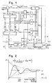
- first function block 1 contains a first function block 1, a second function block 2, a third function block 3, a first enable function block 4, a fourth function block 5, and an optional fifth function block 6 , a monitoring function block 7, a second release function block 8, a third release function block 9 and a first subtraction element 10, which together form an adaptation circuit 11, and a second subtraction element 12, a controller 13 and a analog control system 14.
- a filter 15 or three filters 16, 17 and 18 are also available.
- a control circuit 19 contains the second subtraction element 12, the controller 13 and the controlled system 14, which are connected in series in the sequence given. An output of one component of the control circuit 19 is connected to an input of a component immediately following in the derailleur circuit.
- the controller 13 preferably contains a microcomputer and then processes digital discrete values y [k] of an actual value y [t] of a controlled variable.
- the letter t denotes the time.
- the discrete values y [k] occurring successively in time, periodically with a period T o are numbered consecutively in the order in which they appear and are given an integer number k. In the following, the assumption applies that the period T o is equal to a time unit.
- Each discrete value y [k] of the actual value y [t] of the controlled variable includes a discrete value w [k] of a setpoint of the controlled variable, a discrete value G [k] of a gain factor of the controller 13, and a discrete value u [k] one at the output of the controller 13 available manipulated variable, a discrete value y ′ [k] of a first time derivative of the actual value y [t] of the controlled variable, a discrete value y ⁇ [k] of a second temporal derivative of the actual value y [t] of the controlled variable and a discrete value y ′′′ [k] of a third time derivative of the actual value y [t] of the controlled variable.
- the discrete value y [k] of the actual value y [t] of the controlled variable is compared with the discrete value w [k] of the desired value of the controlled variable by means of the second subtraction element 12 and a discrete desired value / actual value difference w [ k] -y [k] in the controller 13 with the discrete value G [k] of the amplification factor amplified for the generation at the output of the controller 13 of the discrete value u [k] of the manipulated variable, which is then fed to the control path 14 for generation at the output of the Control system 14 of the discrete value y [k] of the actual value y [t] of the controlled variable.
- the discrete value w [k] of the setpoint of the controlled variable is on a plus input of the second subtraction element 12, while the discrete value y [k] of the actual value y [t] of the control variable present at the output of the controlled system 14 on the one hand to a minus input of the second subtraction element 12 and on the other hand directly or via the optional filter 15 to one Input of function block 1 is performed.
- the latter has a separate output for three discrete estimates y ′ [k], y ⁇ [k] and y ′′′ [k] of the first three time derivatives of the actual value y [t] of the controlled variable.
- Each of these separate outputs of the function block 1 is either directly or via an optional filter 16 or 17 or 18 to an associated input of the function blocks 2, 3 and 9.
- the filters 16 to 18 on the one hand and the filter 15 on the other hand are mutually exclusive, ie if the filter 15 is present, the filters 16 to 18 are absent, and vice versa.
- Either the discrete values y [k] of the actual value y [t] of the controlled variable are then filtered in the filter 15 before they are processed further, or the discrete estimated values y ′ [k], y ⁇ [k] and y ′′′ [k]
- Three first time derivatives of the actual value y [t] of the controlled variable are filtered in a filter 16 or 17 or 18 before they are processed further.
- Function block 2 has a first output, at which discrete estimated values d [k] of a damping factor of control loop 19 are present, and a second output, at which discrete estimated values T [k] of a time constant of control loop 19 are present.
- Each of the two outputs of function block 2 is connected to a further input of function block 3.
- the first output of the function block 2 is also connected to a minus input of the first subtraction element 10, while the second output of the function block 2 is additionally connected to a first input of the function block 8 and, if present, of the function block 6.
- a discrete value d Ref [k] of the desired value of the damping factor of the control circuit 19 is passed to a plus input of the first subtraction element 10, the output of which is connected to a first input of the function block 5.
- the output of the controller 13 connected to the input of the controlled system 14 is also via the Monitoring function block 7 led to a second input of function block 8, while the output of function block 3 is connected to an input of function block 4.
- An output of the function block 4 is routed to a second input, an output of the function block 9 to a third input and an output of the function block 8 to a fourth input of the function block 5 and, if present, of the function block 6.
- the output of the function block 5 is with a first parameter input, two outputs of the function block 6, if present, with a second or third parameter input and the output of the function block 1 at which the discrete estimated values y '[k] of the first time derivative of the actual value y [t] of the controlled variable are present, connected to a fourth parameter input of each of the controllers 13, the latter connection possibly being made via the filter 16.
- the discrete value y [k] of the actual value y [t] of the controlled variable is thus compared with the discrete value w [k] of the desired value of the controlled variable by the discrete desired value / actual value difference w [k] -y [ k] is formed, which is then fed to the input of the controller 13, where it is multiplied by the discrete value G [k] of the gain factor of the controller 13 present at the first parameter input of the controller 13 and, if appropriate, by one at the second and third parameter input of the controller 13 pending discrete value T n [k] or T v [k] is provided with a reset time and a lead time.
- the damping factor and the time constant of the control circuit 19 are used as quality criteria.
- An optimal setting of the control loop 19 in the sense of an automatic self-adaptation of the optimally selected quality criteria is achieved by a continuous evaluation during the regulation of the discrete estimated values d [k] and T [k] of the step response of the closed control loop 19 and their gradual optimization by adjusting discrete values G [k] and, if appropriate, T n [k] and T v [k] of the amplification factor, the reset time and the lead time, which are each fed to the controller 13 via its three first parameter inputs.
- function block 1 starting from each discrete value y [k] of the actual value y [t] of the controlled variable, the discrete estimate y ′ [k] of the first time derivative and the discrete estimate y ⁇ [k] of the second time derivative and the discrete estimate y ′′′ [k] of the third time derivative of the controlled variable are determined.
- the discrete values y [k] of the actual value y [t] of the controlled variable used are either unfiltered or previously filtered in the filter 15.
- the discrete estimated values y ′ [k], y ⁇ [k] and y ′′′ [k] of the three time derivatives of the actual value y [t] of the controlled variable are in turn either unfiltered or filtered using filters 16 to 18 for further processing to function blocks 2 , 3 and 9 forwarded.
- the discrete estimated value d [k] of the damping factor of the control loop 19 is in turn compared as the actual value in the first subtraction element 10 with the discrete value d Ref [k] of the desired value of the damping factor of the control loop 19 in order to determine a discrete estimated value d Ref [k] - d [k] a setpoint / actual value difference of the damping factor.
- the setpoint / actual value difference of the damping factor is then in function block 5, if its operation is enabled by the three enable function blocks 4, 8 and 9, the associated discrete Value G [k] of the gain factor is determined, which is then fed to the controller 13 via the first parameter input, where the value of the latter Regulator gain factor is reset each time by setting it equal to the determined discrete value G [k] of the gain factor.
- Optimizing the controller setting according to a quadratic quality criterion provides an oscillatory step response.
- the characteristic equation of the closed control loop 19 has a dominant pair of complex conjugate roots, which decisively determine the shape of the step response.
- Optimal step responses from different control loops look similar in this case. They are made up of exponential functions or a single damped sine wave, while additional harmonics are negligibly small.
- the behavior of the closed control loop 19, regardless of the order of the controlled system 14, can be approximated by a second-order model.
- D1 [k] y ′ [k-1] .y ⁇ [k] - y ⁇ [k-1] .y ′ [k]
- D2 [k] y ′′′ [k-1] .y ′ [k] - y ′ [k-1] .y ′′′ [k]
- D s [k] y ′′′ [k-1] .y ⁇ [k] - y ⁇ [k-1] .y ′′′ [k]
- function block 2 based on the discrete estimates y ′ [k], y ⁇ [k], y ′′′ [k], y ′ [k-1], y ⁇ [k-1] and y, determined and stored in function block 1 ′′′ [K-1] using equations X to XII calculates the discrete estimates D1 [k], D2 [k] and D s [k] and then using equation VIII the discrete estimate T [k] of the time constant and then using the Equation IX the discrete estimate d [k] of the damping factor of the control circuit 19 is determined.
- the filters 15 to 18 cause the signals y [k] or y ′ [k], y ⁇ [k] and y ′′′ [k] to be filtered through low-pass filters if the measured actual value y [t] is Control variable at the output of the controlled system 14 z. B. is noisy.
- T e [k] is the time interval between two adjacent maxima or minima or between two adjacent odd or even zero crossings of the step response.
- the period T e [k] of the oscillations depends only on the discrete estimates T [k] and d [k] of the time constant and the damping factor.
- d [k]> 1 the control process is aperiodic.
- the discrete estimate d [k] of the damping factor thus decisively determines the control quality.
- the discrete estimate d [k] of the damping factor can be regarded as a measure of the quality of the control process.
- M d .d [k] P - ln ⁇ M G .G [k-1] ⁇ where P, M d and M G are three constants.
- ⁇ e M d . ⁇ d [k] - d Ref [k] ⁇ - 1 ⁇ can be adjusted so that the discrete estimate d [k] of the damping factor reaches the currently applicable discrete value d Ref [k] of its setpoint.
- the time constant and the first three time derivatives of the actual value of the controlled variable in function block 3 an associated discrete estimated value ⁇ [k] of a relative approximation error is determined, which is then the Release function block 4 is supplied.
- the determination of the discrete value G [k] of the gain factor, ie the operation of the function block 5, is only released when the determined discrete estimate wert [k] of the relative approximation error has a predetermined value, e.g. B. 1%, does not exceed, since otherwise the determined discrete estimated values T [k] and d [k] are unreliable and unacceptable.
- the range of the manipulated variable at the output of the controller 13 is limited. If the manipulated variable, e.g. B. by a setpoint jump, for a long time in their upper or lower limit saturation range, the controlled variable at the output of the controlled system 14 no longer corresponds to the step response of the closed linear control circuit 19, which is the prerequisite for the correct estimation of the values of the damping factor. In this case, the self-adjustment must be interrupted. After the manipulated variable has left the limit value saturation range, the control circuit 19 needs a certain time before the ascertained estimated values of the damping factor and the time constant are acceptable again. The self-adjustment may therefore only be released after this time has expired. This time depends on the operating speed of the closed control circuit 19 and thus ultimately on the discrete estimated value T [k] of the time constant.
- the discrete value u [k] of the manipulated variable appearing from the controller 13 is continuously monitored and, if it reaches an upper or lower saturation limit value and maintains it for a duration that is greater than the discrete estimated value T [k] of the time constant of the control circuit 19, the determination is made of the discrete value G [k] of the gain factor, ie the operation of the function block 5, is blocked with the aid of the release function block 8 and only released again after the discrete value u [k] of the manipulated variable has exceeded the upper or lower limit saturation range at least during one Has left duration, which is equal to the discrete estimate T [k] of the time constant.
- the function block 8 decides whether and for how long after the discrete value u [k] of the manipulated variable has left the saturation range, the self-adaptation should be blocked or should remain blocked.
- the closed adaptation control loop shown in FIG. 1 realizes a non-linear meshed two-size control, discrete values y [k] of the actual value y [t] of the controlled variable by means of the control loop 19 on the one hand, and discrete values d [k] of the damping factor of the control loop by means of the one hand of the adaptation control loop are regulated.
- the control circuit 19 is arranged in the feedback branch of the adaptation control circuit, the adaptation circuit 11 of the latter representing an additional feedback for the control circuit 19.
- one of the two closed control loops should work significantly slower than the other. Since the control loop 19 should be as fast as possible by nature, the working speed of the adaptation control loop should be a fraction of the working speed of the control loop 19.
- the controller 13 has an integral part characterized by a readjustment time, ie if it is e.g. B. is a PI or a PID controller, then discrete values T n [k] of the reset time in the function block 6, which in this case is always present, must be continually re-adjusted. This is done by determining the discrete value T n [k] of the reset time based on the determined discrete estimate T [k] of the time constant of the control circuit 19 if the determination of the discrete value G [k] of the gain factor is enabled. That is, the operation of the function block 6 is released or blocked simultaneously with that of the function block 5 by the output signals of the function blocks 4, 8 and 9. The newly determined discrete value T n [k] of the reset time is then fed to the controller 13 for the purpose of resetting the value of its reset time.
- a readjustment time ie if it is e.g. B. is a PI or a PID controller
- the estimate of T [k] has a similar spread to that of d [k]
- it is advisable to use the equation to calculate the discrete value T n [k] of the reset time T n [k] T n [k-1] + 0.1.
- the controller 13 in this case has a fourth parameter input for the purpose of supplying the discrete value y ′ [k] determined in the function block 1 and possibly filtered in the filter 16 of the first time derivative of the actual value y [t] of the controlled variable.
- This has the advantage that the possibly necessary filtering of the discrete values y ′ [k] is already carried out in the filter 16 and no longer has to be repeated in the controller 13 itself.
Landscapes
- Engineering & Computer Science (AREA)
- Software Systems (AREA)
- Artificial Intelligence (AREA)
- Computer Vision & Pattern Recognition (AREA)
- Evolutionary Computation (AREA)
- Medical Informatics (AREA)
- Health & Medical Sciences (AREA)
- Physics & Mathematics (AREA)
- General Physics & Mathematics (AREA)
- Automation & Control Theory (AREA)
- Feedback Control In General (AREA)
- Oscillators With Electromechanical Resonators (AREA)
- Control Of Electric Motors In General (AREA)
Claims (12)
- Procédé d'adaptation automatique de paramètres d'un régulateur (13), qui est contenu dans un circuit de régulation (19), qui produit des valeurs discrètes (y[k]) d'une valeur réelle (y[t]) d'une grandeur de régulation, avec au moins un facteur d'amortissement du circuit de régulation (19) en tant que critère de qualité, caractérisé en ce qu'à partir de chaque valeur discrète (y[k]) de la valeur réelle (y[t]) de la grandeur de régulation, on détermine respectivement une valeur estimée discrète (y′[k]) d'une dérivée première dans le temps de la valeur réelle (y[t]) de la grandeur de régulation au moyen de la relation y′[k] = y[k] - y[k-1], qu'à partir d'une valeur estimée discrète (y˝[k]) d'une dérivée seconde dans le temps de la valeur réelle (y[t]) de la grandeur de régulation au moyen de la relation y˝[k] = y′[k] - y′[k-1], on détermine respectivement une valeur estimée discrète y‴[k] d'une dérivée troisième dans le temps de la valeur réelle (y[t]) de la grandeur de régulation au moyen de la relation y‴[k] = y‴[k] - y˝[k-1], qu'au moyen des valeurs estimées discrètes (y′[k], y˝[k], y‴[k]) des trois premières dérivées dans le temps de la valeur (y[t]) de la grandeur de régulation, on détermine respectivement une valeur estimée discrète d[k] du faccteur d'amortissement du circuit de régulation (19) au moyen de la relation d[k] = -D₂[k]/{2.T[k].DS[k]}, et une valeur estimée discrète T[k] d'une constante de temps du circuit de régulation (19) au moyen de la relation T[k] = {-D₁[k]/DS[k]}1/2 avec D₁[k] = y′[k].y˝[k] - y˝[k-1].y′[k], D₂[k] = y‴[k].y′[k] - y′[k-1].y‴[k], D₃[k] = y‴[k].y˝[k] - y˝[k-1].y‴[k], y[k] étant une valeur discrète, qui vient précisément d'être mesurée, et y[k-1] étant une valeur discrète mesurée juste avant la précédente, de la valeur réelle (y[t]) de la grandeur de régulation, ces deux valeurs étant séparées dans le temps, d'une unité de temps, et y′[k-1], y˝[k-1] et y‴[k-1] étant des valeurs estimées discrètes précédentes des trois premières dérivées dans le temps de la valeur (y[t]) de la grandeur de régulation, qui était valable jusqu'en dernier lieu, et la valeur estimée discrète d[k] du facteur d'amortissement du circuit de régulation (19) en tant que valeur réelle est comparée respectivement à une valeur discrète DRef[k] d'une valeur de consigne du facteur d'amortissement du circuit de régulation (19) pour la détermination d'une valeur estimée discrète DRef[k] - d[k] d'une différence valeur de consigne/valeur réelle du facteur d'amortisseur, à partir de la valeur estimée discrète déterminée DRef[k] - d[k] de la différence valeur de consigne/valeur réelle on détermine respectivement une valeur discrète G[k] d'un facteur d'amplification, qui est envoyé au régulateur (13), au moyen de la relation G[k] = G[k-1]{1 + M.d[k] - M.dRef[k]}, M étant une constante, dRef[k] une valeur discrète précisément valable de la valeur de consigne du facteur d'amortissement du circuit de régulation (19), et G[k-1] une valeur discrète précédente du facteur d'amplification, qui était valable jusqu'en dernier lieu, et qu'on règle la valeur d'un facteur d'amplification du régulateur (13) de manière qu'elle soit respectivement égale à la valeur discrète déterminée G[k] du facteur d'amplification.
- Procédé selon la revendication 1, caractérisé en ce que la constante N est inversement proportionnelle à un multiple (r.T[k]) de la valeur estimée discrète (T[k]) de la constante de temps du circuit de régulation (19).
- Procédé selon la revendication 1 ou 2, caractérisé en ce que le nombre de chiffres décimaux des valeurs estimées discrètes déterminées (y′[]k, y˝[k], y‴[k]) des trois premières dérivées dans le temps de la valeur (y[t]) de la grandeur de régulation est respectivement contrôlé et que la détermination de la valeur discrète (G[k]) du facteur d'amplification n'est permise que lorsque le nombre de chiffres décimaux atteint une valeur prédéterminée.
- Procédé selon l'une des revendications 1 à 3, caractérisé en ce qu'à partir des valeurs estimées discrètes déterminées (d[k], T[k], y′[k], y˝[k], y‴[k]) du facteur d'amortissement, de la constante de temps et des trois premières dérivées dans le temps de la valeur réelle (y[t]) de la grandeur de régulation, on détermine respectivement une valeur estimée discrète (Φ[k]) d'une erreur d'approximation relative et que la détermination de la valeur discrète (G[k]) du facteur d'amplification est autorisée respectivement seulement lorsque la valeur estimée discrète déterminée (Φ[k]) de l'erreur d'approximation relative ne dépasse pas une valeur prédéterminée (par exemple 1 %).
- Procédé selon la revendication 4, caractérisé en ce qu'une valeur estimée discrète (Φ[k]) de l'erreur d'approximation relative est déterminée respectivement au moyen de la relation

- Procédé selon l'une des revendications 1 à 5, caractérisé en ce que chaque valeur discrète (u[k]), qui apparaît à la sortie du régulateur (13), et d'une grandeur de régulation est contrôlée en permanence et que, dans le cas où cette valeur est contenue dans une zone supérieure ou inférieure de saturation de valeur limite pendant une durée, qui est supérieure à la valeur estimée discrète (T[k]) de la constante de temps du circuit de régulation (19), la détermination de la valeur discrète (G[k]) du facteur d'amplification est bloquée et n'est à nouveau autorisée que lorsque la valeur discrète (u[k]) de la grandeur de régulation a quitté la zone supérieure ou inférieure de saturation de valeur limite pendant une durée qui est égale à la valeur estimée discrète (T[k]) de la constante de temps.
- Procédé selon l'une des revendications 1 à 6, caractérisé en ce que le régulateur (13) possède une partie intégrale, caractérisé par une durée d'ajustement, que respectivement une valeur discrète (Tn[k]) de la durée d'ajustement est déterminée à partir de la valeur estimée discrète déterminée (T[k]) de la constante de temps du circuit de régulation (19), dans le cas où la détermination de la valeur discrète (G[k]) du facteur d'amplification est autorisée, et que la valeur discrète déterminée (Tn[k]) de la durée d'ajustement est envoyée au régulateur (13), en vue d'un nouveau réglage de la valeur par cette durée d'ajustement.
- Procédé selon la revendication 7, caractérisé en ce qu'une valeur discrète (Tn[k]) de la durée d'ajustement est déterminée respectivement au moyen de la relation Tn[k] = Tn[k-1] + 0,1.[2π.T[k-1] - Tn[k-1]}, T[k-1] et Tn[k-1] étant des valeurs discrètes précédentes de la constante de temps du circuit de régulation (19) ou de la durée d'ajustement, qui était valable jusqu'alors en dernier lieu.
- Procédé selon la revendication 7 ou 8, caractérisé en ce que le régulateur (13) possède une partie différentielle, caractérisé par une durée de dérivation, qu'une valeur discrète (Tv[k]) de la durée de dérivation est déterminée à partir de la valeur discrète déterminée (Tn[k]) de la durée d'ajustement, dans le cas où la détermination de la valeur discrète (G[k]) du facteur d'amplification est autorisée, et que la valeur discrète déterminée (Tv[k]) de la durée de dérivation est envoyée au régulateur (13) en vue d'un nouveau de réglage de la valeur par la durée de dérivation du régulateur.
- Procédé selon la revendication 9, caractérisé en ce qu'une valeur discrète (Tv[k]) de la durée de dérivation est déterminée respectivement au moyen de la relation Tv[k] = Tn[k]/4, Tn[k] étant la valeur discrète de la durée d'ajustement du régulateur (13).
- Procédé selon l'une des revendications 1 à 10, caractérisé en ce que la valeur discrète (y[k]) et la valeur réelle (y[t]) de la grandeur de régulation sont filtrées dans un filtre (15) avant la poursuite de leur traitement.
- Procédé selon l'une des revendications 1 à 10, caractérisé en ce que les valeurs estimées discrètes (y′[k], y˝[k], y‴[k]) des trois dérivées dans le temps de la valeur réelle (y[t]) de la grandeur de régulation sont filtrées dans des filtres respectifs (16, 17, 18) avant la poursuite de leur traitement.
Applications Claiming Priority (2)
| Application Number | Priority Date | Filing Date | Title |
|---|---|---|---|
| CH356391 | 1991-12-04 | ||
| CH3563/91 | 1991-12-04 |
Publications (2)
| Publication Number | Publication Date |
|---|---|
| EP0545009A1 EP0545009A1 (fr) | 1993-06-09 |
| EP0545009B1 true EP0545009B1 (fr) | 1994-12-07 |
Family
ID=4258706
Family Applications (1)
| Application Number | Title | Priority Date | Filing Date |
|---|---|---|---|
| EP92116070A Expired - Lifetime EP0545009B1 (fr) | 1991-12-04 | 1992-09-19 | Procédé d'adaptation automatique des coefficients d'un régulateur |
Country Status (4)
| Country | Link |
|---|---|
| EP (1) | EP0545009B1 (fr) |
| AT (1) | ATE115304T1 (fr) |
| DE (1) | DE59200913D1 (fr) |
| DK (1) | DK0545009T3 (fr) |
Families Citing this family (2)
| Publication number | Priority date | Publication date | Assignee | Title |
|---|---|---|---|---|
| DE19525907A1 (de) * | 1995-07-06 | 1997-01-09 | Hartmann & Braun Ag | Selbsteinstellbare Regeleinrichtung und Verfahren zur Selbsteinstellung dieses Reglers |
| US5793022A (en) * | 1996-09-12 | 1998-08-11 | Applied Materials, Inc. | Adaptive temperture controller and method of operation |
Family Cites Families (1)
| Publication number | Priority date | Publication date | Assignee | Title |
|---|---|---|---|---|
| US3727035A (en) * | 1971-06-03 | 1973-04-10 | Phillips Petroleum Co | Pulse test of digital control system |
-
1992
- 1992-09-19 EP EP92116070A patent/EP0545009B1/fr not_active Expired - Lifetime
- 1992-09-19 DK DK92116070.1T patent/DK0545009T3/da active
- 1992-09-19 DE DE59200913T patent/DE59200913D1/de not_active Expired - Fee Related
- 1992-09-19 AT AT92116070T patent/ATE115304T1/de not_active IP Right Cessation
Also Published As
| Publication number | Publication date |
|---|---|
| DE59200913D1 (de) | 1995-01-19 |
| DK0545009T3 (da) | 1995-05-29 |
| EP0545009A1 (fr) | 1993-06-09 |
| ATE115304T1 (de) | 1994-12-15 |
Similar Documents
| Publication | Publication Date | Title |
|---|---|---|
| DE10231417B4 (de) | Modellfreie Adaptation eines Prozessreglers (Prozesssteuereinheit) | |
| DE2735012C2 (fr) | ||
| DE69835626T2 (de) | Verfahren zur Erzeugung eines gefilterten Signals sowie ein numerisches Filter | |
| DE102004019352B4 (de) | Zustandsbasierter adaptiver Feedback-/Feedforward-PID-Regler (PID-Steuerungseinheit) | |
| DE102004058238A1 (de) | Adaptive, multivariable Prozesssteuerung, die Modellschaltung und Attribut-Interpolation nutzt | |
| DE3911186A1 (de) | Verfahren und vorrichtung zur automatischen einstellung von pid-konstanten | |
| DE2354638A1 (de) | Verfahrensregelanlage | |
| DE1588341A1 (de) | Regelkreis | |
| EP0520233A2 (fr) | Dispositif pour l'identification d'un système commandé | |
| EP0545009B1 (fr) | Procédé d'adaptation automatique des coefficients d'un régulateur | |
| EP0752630B1 (fr) | Contrôleur et méthode pour l'auto-ajustement du contrôleur | |
| EP3542229B1 (fr) | Dispositif et procédé de détermination des paramètres d'un dispositif de réglage | |
| EP3507656B1 (fr) | Dispositif de régulation avec ajustabilité du comportement de régulation | |
| DE102006048421B4 (de) | Verfahren zum Regeln eines Istzuges auf einen Sollzug mittels eines mittels eines Modells der Zugregelstrecke adaptierten Zugreglers | |
| DE10213533A1 (de) | Verfahren und Regler zur Regelung mindestens einer Komponente einer technischen Anlage | |
| EP3244270B1 (fr) | Dispositif de reglage a compensation d'erreur adaptative | |
| DE4329484A1 (de) | Positioniervorrichtung | |
| DE10060125A1 (de) | Verfahren zur Regelung eines verzögerungsbehafteten Prozesses mit Ausgleich sowie Regeleinrichtung zur Durchführung des Verfahrens | |
| DE4100064A1 (de) | Verfahren und schaltungsanordnung zur vermeidung eines reset-windup-effektes bei einer regelschaltung | |
| DE3931727C2 (de) | Verfahren zum Ausregeln der Regelabweichung bei einer Regelstrecke, insbesondere mit sich zeitlich ändernden Übertragungsparametern | |
| EP0704776B1 (fr) | Procédé de réglage des paramètres d'un régulateur PI ou PID | |
| DE2528313C2 (de) | Verfahren zur schrittregelung mit einem dreipunktschalter mit einstellbarer totzonenbreite | |
| DE1804898A1 (de) | Stetigaehnlicher PID-Relaisregler | |
| DE3239015C2 (fr) | ||
| EP0238462B1 (fr) | Procédé et installation pour la régulation du processus de soudage au cours du soudage à l'arc |
Legal Events
| Date | Code | Title | Description |
|---|---|---|---|
| PUAI | Public reference made under article 153(3) epc to a published international application that has entered the european phase |
Free format text: ORIGINAL CODE: 0009012 |
|
| AK | Designated contracting states |
Kind code of ref document: A1 Designated state(s): AT BE CH DE DK FR GB IT LI NL SE |
|
| 17P | Request for examination filed |
Effective date: 19930727 |
|
| 17Q | First examination report despatched |
Effective date: 19930928 |
|
| GRAA | (expected) grant |
Free format text: ORIGINAL CODE: 0009210 |
|
| AK | Designated contracting states |
Kind code of ref document: B1 Designated state(s): AT BE CH DE DK FR GB IT LI NL SE |
|
| REF | Corresponds to: |
Ref document number: 115304 Country of ref document: AT Date of ref document: 19941215 Kind code of ref document: T |
|
| RAP2 | Party data changed (patent owner data changed or rights of a patent transferred) |
Owner name: LANDIS & GYR TECHNOLOGY INNOVATION AG |
|
| GBT | Gb: translation of ep patent filed (gb section 77(6)(a)/1977) |
Effective date: 19941212 |
|
| REF | Corresponds to: |
Ref document number: 59200913 Country of ref document: DE Date of ref document: 19950119 |
|
| ET | Fr: translation filed | ||
| ITF | It: translation for a ep patent filed |
Owner name: STUDIO JAUMANN |
|
| REG | Reference to a national code |
Ref country code: DK Ref legal event code: T3 |
|
| PLBE | No opposition filed within time limit |
Free format text: ORIGINAL CODE: 0009261 |
|
| STAA | Information on the status of an ep patent application or granted ep patent |
Free format text: STATUS: NO OPPOSITION FILED WITHIN TIME LIMIT |
|
| 26N | No opposition filed | ||
| PGFP | Annual fee paid to national office [announced via postgrant information from national office to epo] |
Ref country code: CH Payment date: 19971212 Year of fee payment: 6 |
|
| PGFP | Annual fee paid to national office [announced via postgrant information from national office to epo] |
Ref country code: GB Payment date: 19980813 Year of fee payment: 7 |
|
| PGFP | Annual fee paid to national office [announced via postgrant information from national office to epo] |
Ref country code: AT Payment date: 19980820 Year of fee payment: 7 |
|
| PGFP | Annual fee paid to national office [announced via postgrant information from national office to epo] |
Ref country code: FR Payment date: 19980916 Year of fee payment: 7 |
|
| PGFP | Annual fee paid to national office [announced via postgrant information from national office to epo] |
Ref country code: BE Payment date: 19980923 Year of fee payment: 7 Ref country code: DK Payment date: 19980923 Year of fee payment: 7 Ref country code: NL Payment date: 19980923 Year of fee payment: 7 Ref country code: SE Payment date: 19980923 Year of fee payment: 7 |
|
| PG25 | Lapsed in a contracting state [announced via postgrant information from national office to epo] |
Ref country code: CH Free format text: LAPSE BECAUSE OF NON-PAYMENT OF DUE FEES Effective date: 19980930 Ref country code: LI Free format text: LAPSE BECAUSE OF NON-PAYMENT OF DUE FEES Effective date: 19980930 |
|
| PGFP | Annual fee paid to national office [announced via postgrant information from national office to epo] |
Ref country code: DE Payment date: 19981030 Year of fee payment: 7 |
|
| REG | Reference to a national code |
Ref country code: CH Ref legal event code: PL |
|
| PG25 | Lapsed in a contracting state [announced via postgrant information from national office to epo] |
Ref country code: GB Free format text: LAPSE BECAUSE OF NON-PAYMENT OF DUE FEES Effective date: 19990919 Ref country code: AT Free format text: LAPSE BECAUSE OF NON-PAYMENT OF DUE FEES Effective date: 19990919 Ref country code: DK Free format text: LAPSE BECAUSE OF NON-PAYMENT OF DUE FEES Effective date: 19990919 |
|
| PG25 | Lapsed in a contracting state [announced via postgrant information from national office to epo] |
Ref country code: SE Free format text: THE PATENT HAS BEEN ANNULLED BY A DECISION OF A NATIONAL AUTHORITY Effective date: 19990929 |
|
| PG25 | Lapsed in a contracting state [announced via postgrant information from national office to epo] |
Ref country code: BE Free format text: LAPSE BECAUSE OF NON-PAYMENT OF DUE FEES Effective date: 19990930 |
|
| BERE | Be: lapsed |
Owner name: LANDIS & GYR TECHNOLOGY INNOVATION A.G. Effective date: 19990930 |
|
| PG25 | Lapsed in a contracting state [announced via postgrant information from national office to epo] |
Ref country code: NL Free format text: LAPSE BECAUSE OF NON-PAYMENT OF DUE FEES Effective date: 20000401 |
|
| GBPC | Gb: european patent ceased through non-payment of renewal fee |
Effective date: 19990919 |
|
| EUG | Se: european patent has lapsed |
Ref document number: 92116070.1 |
|
| PG25 | Lapsed in a contracting state [announced via postgrant information from national office to epo] |
Ref country code: FR Free format text: LAPSE BECAUSE OF NON-PAYMENT OF DUE FEES Effective date: 20000531 |
|
| NLV4 | Nl: lapsed or anulled due to non-payment of the annual fee |
Effective date: 20000401 |
|
| REG | Reference to a national code |
Ref country code: DK Ref legal event code: EBP |
|
| PG25 | Lapsed in a contracting state [announced via postgrant information from national office to epo] |
Ref country code: DE Free format text: LAPSE BECAUSE OF NON-PAYMENT OF DUE FEES Effective date: 20000701 |
|
| REG | Reference to a national code |
Ref country code: FR Ref legal event code: ST |
|
| PG25 | Lapsed in a contracting state [announced via postgrant information from national office to epo] |
Ref country code: IT Free format text: LAPSE BECAUSE OF NON-PAYMENT OF DUE FEES;WARNING: LAPSES OF ITALIAN PATENTS WITH EFFECTIVE DATE BEFORE 2007 MAY HAVE OCCURRED AT ANY TIME BEFORE 2007. THE CORRECT EFFECTIVE DATE MAY BE DIFFERENT FROM THE ONE RECORDED. Effective date: 20050919 |
|
| PGFP | Annual fee paid to national office [announced via postgrant information from national office to epo] |
Ref country code: IT Payment date: 20070830 Year of fee payment: 16 |
|
| PGRI | Patent reinstated in contracting state [announced from national office to epo] |
Ref country code: IT Effective date: 20091201 |
|
| PGRI | Patent reinstated in contracting state [announced from national office to epo] |
Ref country code: IT Effective date: 20091201 |