EP0544881B1 - Backlash adjustment mechanism - Google Patents
Backlash adjustment mechanism Download PDFInfo
- Publication number
- EP0544881B1 EP0544881B1 EP92913328A EP92913328A EP0544881B1 EP 0544881 B1 EP0544881 B1 EP 0544881B1 EP 92913328 A EP92913328 A EP 92913328A EP 92913328 A EP92913328 A EP 92913328A EP 0544881 B1 EP0544881 B1 EP 0544881B1
- Authority
- EP
- European Patent Office
- Prior art keywords
- gear
- idler gear
- mounting
- pivot
- idler
- Prior art date
- Legal status (The legal status is an assumption and is not a legal conclusion. Google has not performed a legal analysis and makes no representation as to the accuracy of the status listed.)
- Expired - Lifetime
Links
- 230000007246 mechanism Effects 0.000 title abstract description 16
- 238000002485 combustion reaction Methods 0.000 claims description 7
- 230000013011 mating Effects 0.000 abstract description 14
- 238000012423 maintenance Methods 0.000 abstract description 5
- 238000000034 method Methods 0.000 description 5
- 238000003754 machining Methods 0.000 description 3
- 238000005259 measurement Methods 0.000 description 2
- 230000006835 compression Effects 0.000 description 1
- 238000007906 compression Methods 0.000 description 1
- 238000003801 milling Methods 0.000 description 1
Images




Classifications
-
- F—MECHANICAL ENGINEERING; LIGHTING; HEATING; WEAPONS; BLASTING
- F16—ENGINEERING ELEMENTS AND UNITS; GENERAL MEASURES FOR PRODUCING AND MAINTAINING EFFECTIVE FUNCTIONING OF MACHINES OR INSTALLATIONS; THERMAL INSULATION IN GENERAL
- F16H—GEARING
- F16H57/00—General details of gearing
- F16H57/02—Gearboxes; Mounting gearing therein
- F16H57/021—Shaft support structures, e.g. partition walls, bearing eyes, casing walls or covers with bearings
- F16H57/022—Adjustment of gear shafts or bearings
-
- F—MECHANICAL ENGINEERING; LIGHTING; HEATING; WEAPONS; BLASTING
- F16—ENGINEERING ELEMENTS AND UNITS; GENERAL MEASURES FOR PRODUCING AND MAINTAINING EFFECTIVE FUNCTIONING OF MACHINES OR INSTALLATIONS; THERMAL INSULATION IN GENERAL
- F16H—GEARING
- F16H57/00—General details of gearing
- F16H57/12—Arrangements for adjusting or for taking-up backlash not provided for elsewhere
-
- F—MECHANICAL ENGINEERING; LIGHTING; HEATING; WEAPONS; BLASTING
- F16—ENGINEERING ELEMENTS AND UNITS; GENERAL MEASURES FOR PRODUCING AND MAINTAINING EFFECTIVE FUNCTIONING OF MACHINES OR INSTALLATIONS; THERMAL INSULATION IN GENERAL
- F16H—GEARING
- F16H57/00—General details of gearing
- F16H57/02—Gearboxes; Mounting gearing therein
- F16H57/021—Shaft support structures, e.g. partition walls, bearing eyes, casing walls or covers with bearings
- F16H57/022—Adjustment of gear shafts or bearings
- F16H2057/0222—Lateral adjustment
- F16H2057/0224—Lateral adjustment using eccentric bushes
Definitions
- This invention relates to gearing systems and more particularly to a backlash adjustment mechanism for gearing systems.
- Backlash adjustment methods are known which mount an idler gear on an adjustable bracket to provide adjustment control between its mating gears. This method accomplishes adjustment, but makes it necessary to position the center distances between the idler and both its mating gears before securing the idler into place.
- Another backlash adjustment method improves upon the positioning problem, set forth above, through the backlash adjustment being made only between the idler gear and one of its mating gears while eliminating the need for adjustment between the idler gear and the other of its mating gears.
- This is accomplished through the use of connector of fixed length. With the idler gear mounted on an adjustment bracket, the connector is attached to the idler gear and one mating gear establishing a fixed center distance betwen the two gears. Backlash adjustment can then be made btween the idler gear and the other mating gear without affecting this fixed center distance provided by the connector.
- This backlash adjustment method requires the use of both the connector and the adjustment bracket.
- the backlash adjustment method further requires complicated machining of standard parts in order to mount and thereby utilize the invention.
- US-A-3502059 discloses a gear train with backlash adjustment, the gear train including a first gear having a first centerline, a second gear having a second centerline, an idler gear having a third centerline drivingly connecting the first and the second gear, and an idler gear mounting rotatably supporting the idler gear and being releasably connected to a fixed member and establishing a movable axis coincidental with the centerline of the idler gear, and, according to the present invention, such a gear train is characterised in that said idler gear meshes directly with the first and the second gear, a pivot is fixedly connected to said fixed member with the idler gear mounting being pivotal thereabout, and said pivot is disposed between the centerlines of the idler gear and the first gear and substantially on a line intersecting the centerlines of the idler gear and the first gear so that a center distance between the idler gear and the second gear can be adjusted while maintaining a substantially fixed distance between the idler gear and the first gear.
- the new gear train is particularly applicable to an internal combustion engine having a cylinder block rotatably mounting a crankshaft; a cylinder head removably connected to the cylinder block; a camshaft rotatably mounted within the internal combustion engine; with the gear train driving the camshaft from the crankshaft, the idler gear mounting being releasably connected to the cylinder block, and the pivot being fixedly connected to the cylinder block.
- the backlash adjustment of the prior art can only be accomplished with the use of both a connector and an adjustment bracket.
- the connector is used to maintain a fixed center distance between an idler gear and one of its mating gears, while the adjustment bracket mounts the idler gear allowing it to pivot in a plurality of adjustment positions.
- the prior art also requires complicated machining of the cylinder block in order to mount and secure the parts necessary to accomplish the backlash adjustment function.
- the present invention will allow the adjustment of backlash with fewer parts and minimal machining to the cylinder block.
- the present invention also utilizes the benefit of a geometric alignment relationship between two gears to accomplish the same function as the prior art connector in maintaining a fixed center distance between the idler gear and one of its mating gears.
- An internal combustion engine of the in-line type is illustrated at 10 having a cylinder block 11 rotatably mounting a crankshaft 12.
- a removably connected cylinder head 13 is mounted at the upper end of the cylinder block 11 in a conventional manner.
- An overhead camshaft 14 is rotatably mounted within the cylinder head 13, and is used to operate the engine valves (not shown).
- a camshaft gear train 17 is enclosed in a gear train cover 16 and drives the camshaft 14 from the crankshaft 12.
- the camshaft gear train 17 includes a drive gear 18 secured to the crankshaft 12 for rotation therewith.
- the drive gear 18 drivingly meshes with cluster idler gears 19 and 21, respectively, which are conventionally, rotatably mounted to the cylinder block 11.
- An idler gear 22 is in meshing engagement with the cluster idler gear 21 and is also conventionally, rotatably mounted to the cylinder block 11.
- An adjustable idler gear 23 is in direct meshing engagement with the idler gear 22, and, in turn, directly engages a camshaft gear 24 mounted on the camshaft 14 for rotation therewith to drivingly interconnect the idler gear 22 and the camshaft gear 24.
- the camshaft gear train 17 is shown with several gears, it is recognized that the camshaft gear train may have a minimum of three gears, the idler gear 22 acting as a drive gear, the adjustable idler gear 23, and the camshaft gear 24.
- a backlash adjustment mechanism 26 provides a means 30 for adjusting the backlash between the adjustable idler gear 23 and the camshaft gear 24, and includes a body 27 having a pivot 28, such as a shaft, extending outwardly therefrom and a plurality of threaded holes 29 with the body 27 being mounted on the cylinder block 11.
- An idler gear mounting 31, such as a rotor, has an off-center mounting bore 32 and a plurality of slotted holes 33, and is eccentrically and pivotally mounted on the pivot 28 establishing a movable axis 34 through the centerline of the rotor 31.
- the adjustable idler gear 23 is rotatably mounted on the rotor 31.
- a thrust plate 37 having a plurality of holes 38 secures the rotor 31 to the shaft 28 while retaining the adjustable idler gear 23 on the rotor 31.
- the thrust plate 37 is secured to the body 27 by a securing means 39 which includes a plurality of studs 41, 42, a bolt 43, and a plurality of nuts 44 and 45.
- the studs 41 and 42 pass through the slotted holes 33 located in the rotor 31 and are threaded into the threaded holes 29 of the body 27.
- the bolt 43 passes through a hole in the shaft 28 of the body 27 and is threaded into a threaded hole of the cylinder block 11.
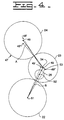
- a geometric alignment 47 relationship of the camshaft gear 24, the adjustable idler gear 23, and the idler gear 22 is shown in Fig. 4 along with a plurality of centerlines 48, 49, and 51 of the gears 24, 23, and 22, respectively.
- the centerlines 48, 49, and 51 also correspond to the nominal adjustment position of the camshaft gear 24, the adjustable idler gear 23, and the idler gear 22 at initial assembly.
- the nominal adjustment position 49 of the adjustable idler gear 23 also represents the nominal adjustment position of the rotor 31 at initial assembly and is coincident with the movable axis 34.
- a known nominal center distance represented by a line A is the distance between the centerline 48 of the camshaft gear 24 and the centerline 49 of the adjustable idler gear 23.
- a fixed nominal center distance represented by a line B is the distance between the centerline 49 of the adjustable idler gear 23 and the centerline 51 of the idler gear 22.
- a pivot point 52 is the center of the shaft 28 of the body 27 and is positioned essentially on center distance line B.
- the camshaft gear 24 may be moved out of its nominal adjustment position 48 due to wear or maintenance disturbances making center distance adjustment necessary between the camshaft gear 24 and the adjustable idler gear 23.
- a means 54 is provided for pivoting the rotor 31 on the shaft 28 around the pivot point 52 to adjust the center distance between the camshaft gear 24 and the adjustable idler gear 23.
- the pivoting means 54 includes the establishment of a plurality of adjustment positions between 49' and 49", where 49' and 49" illustrate the extreme adjustment positions allowable by the slotted holes 33 of the rotor 31.
- An arcuate path 53 is created about the pivot point 52 as the movable axis 34 rotates between the adjustment positions 49'-49".
- the reference numerals 48' and 48" illustrate the extreme movement positions available for the camshaft gear 24 in relation to the allowable adjustment positions 49' and 49", although it should be noted that the camshaft gear 24 may move to an infinite number of positions between 48' and 48" due to wear or maintenance disturbances.
- the backlash adjustment mechanism 26 provides a means 56 for adjusting the backlash between the adjustable idler gear 23 and the camshaft gear 24.
- the backlash adjustment mechanism 26 includes an idler gear mounting 58, such as a body, having a shaft 60 extending outwardly therefrom, a plurality of slotted holes 62, and a dowel hole 64.
- the body 58 is releasably mounted on the cylinder block 11 by a fastening means 65, which includes a plurality of studs 66 and a plurality of nuts 68.
- a pivot 70 such as a dowel pin, is fixedly secured to the block and extends into the dowel hole 64 to allow pivotal movement of the body 58 and to establish a movable axis 72 through the centerline of the shaft 60 coincident with the centerline 49 of the adjustable idler gear 23.
- the shaft 60 of the body 58 has a plurality of threaded holes 74 extending into the shaft 60 and terminating near the body 58.
- the adjustable idler gear 23 is rotatably mounted on the shaft 60.
- a thrust plate 76 having a plurality of holes 78 is mounted to the shaft 60 of the body 58 by a securing means 80, such as a plurality of bolts, to retain the adjustable idler gear 23 on the shaft 60.
- the adjustable idler gear 23 has a plurality of access slots 81 formed therein to provide access to the plurality of studs 66 and nuts 68.
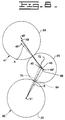
- a geometric alignment 82 relationship of the camshaft gear 24, the adjustable idler gear 23, and the idler gear 22 is shown for the second embodiment of the backlash adjustment mechanism 26 in Fig. 8.
- a pivot point 84 is located at the center of the dowel pin 70 and is positioned essentially on center distance line B.
- a means 86, shown in Fig. 6, is provided for pivoting the body 58 around the pivot point 84 to adjust the center distance between the camshaft gear 24 and the adjustable idler gear 23.
- An arcuate path 88 is created about the pivot point 84 as the movable axis 72 pivots between the adjustment positions 49'-49".
- the backlash adjustment mechanism 26 provides the ability to adjust backlash between the adjustable idler gear 23 and the camshaft gear 24 while maintaining a substantially fixed center distance between the adjustable idler gear 23 and the idler gear 22.
- adjustment begins by loosening the nuts 44, 45, and 46 on the thrust plate 37, leaving the studs 41, 42, and 43 extending through the thrust plate 37.
- the known nominal center distance line A is used as a measure to adjust the center distance, indicated by backlash measurements, between the camshaft gear 24 and the adjustable idler gear 23.
- the slotted holes 33 of the rotor 31 permit a plurality of adjustment positions on the arcuate path 53, between 49' and 49", by pivoting with the rotor about the pivot point 52 of the shaft 28.
- the slotted holes 33 thereby, allow adjustment of the center distance of the adjustable idler gear 23 with respect to the camshaft gear 24 whenever the camshaft gear 24 moves out of it's nominal adjustment position 48.
- the geometric alignment 47 relationship of the pivot point 52, in respect to the fixed center distance line B provides a substantially fixed center distance between the adjustable idler gear 23 and the idler gear 22, well within the desired backlash tolerance range, throughout the adjustment of the adjustable idler gear 23 in respect to the camshaft gear 24. This geometric alignment 47 relationship eliminates the need to adjust backlash between the adjustable idler gear 23 and the idler gear 22, while backlash adjustment is available for any movement of the camshaft gear 24 between 48' and 48".
- adjustment begins by loosening the nuts 68 to allow the body 58 to pivot freely about the dowel pin 70.
- the known nominal center distance A is used as a measure to adjust the center distance, indicated by backlash measurements, between the camshaft gear 24 and the adjustable idler gear 23.
- the slotted holes 62 of the body 58 permit a plurality of adjustment positions along the arcuate path 88, between 49' and 49" by pivoting with the body 58 about the dowel pin 70.
- the slotted holes 62 thereby, allow adjustment of the center distance of the adjustable idler gear 23 with respect to the camshaft gear 24 whenever the camshaft gear 24 moves out of it's nominal adjustment position 48.
- the geometric alignment 82 relationship of the pivot point 84 in respect to the fixed center distance line B functions in similar manner as that of the geometric alignment 47 relationship of the first embodiment.
- the backlash adjustment is completed by tightening the plurality of nuts 68 thereby securing the body 58 to the cylinder block 11.
- the adjustable idler gear 23 is rotatably mounted on the shaft 60 of the body 58 and the thrust plate 76 is mounted to the shaft 60 of the body 58 to retain the adjustable idler gear 23.
- the present invention provides an improved means to adjust for backlash between the adjustable idler gear and the camshaft gear.
- the present invention utilizes a simplified structure consisting of an idler gear mounting, such as a body having a shaft or an eccentrically and pivotally mounted rotor, which mount the adjustable idler gear to provide both the ability for adjustment and a geometric alignment which substantially fixes the center distance between the adjustable idler gear and one of its mating gears, eliminating the need for adjustment between the two gears.
Landscapes
- Engineering & Computer Science (AREA)
- General Engineering & Computer Science (AREA)
- Mechanical Engineering (AREA)
- Valve-Gear Or Valve Arrangements (AREA)
- Gears, Cams (AREA)
- Valve Device For Special Equipments (AREA)
- Devices For Conveying Motion By Means Of Endless Flexible Members (AREA)
- Paper (AREA)
- Body Structure For Vehicles (AREA)
Applications Claiming Priority (3)
| Application Number | Priority Date | Filing Date | Title |
|---|---|---|---|
| WOPCT/US91/04479 | 1991-06-24 | ||
| US9104479 | 1991-06-24 | ||
| PCT/US1992/004364 WO1993000530A1 (en) | 1991-06-24 | 1992-05-26 | Backlash adjustment mechanism |
Publications (3)
| Publication Number | Publication Date |
|---|---|
| EP0544881A1 EP0544881A1 (en) | 1993-06-09 |
| EP0544881A4 EP0544881A4 (enExample) | 1994-12-21 |
| EP0544881B1 true EP0544881B1 (en) | 1997-01-29 |
Family
ID=22225627
Family Applications (1)
| Application Number | Title | Priority Date | Filing Date |
|---|---|---|---|
| EP92913328A Expired - Lifetime EP0544881B1 (en) | 1991-06-24 | 1992-05-26 | Backlash adjustment mechanism |
Country Status (6)
| Country | Link |
|---|---|
| EP (1) | EP0544881B1 (enExample) |
| AU (1) | AU651906B2 (enExample) |
| BR (1) | BR9205342A (enExample) |
| CA (1) | CA2088277A1 (enExample) |
| DE (1) | DE69217181T2 (enExample) |
| WO (1) | WO1993000530A1 (enExample) |
Cited By (2)
| Publication number | Priority date | Publication date | Assignee | Title |
|---|---|---|---|---|
| CN103422927A (zh) * | 2012-05-15 | 2013-12-04 | 曼卡车和巴士股份公司 | 用于气门控制式内燃发动机的正时传动件 |
| EP4256218A4 (en) * | 2020-12-03 | 2024-10-09 | Cummins, Inc. | Geartrain anti-backlash linkage |
Families Citing this family (17)
| Publication number | Priority date | Publication date | Assignee | Title |
|---|---|---|---|---|
| GB2305990B (en) * | 1995-10-03 | 1999-05-26 | Perkins Ltd | A method and a device for setting backlash between gears in a gear train |
| US5931052A (en) * | 1996-06-13 | 1999-08-03 | Simpson International (Uk) Ltd. | Crankshaft gear torsional vibration isolator assembly for an engine |
| US6109129A (en) | 1997-05-08 | 2000-08-29 | Cummins Engine Company, Inc. | Apparatus and method for adjusting a gear |
| US5979259A (en) * | 1997-05-08 | 1999-11-09 | Cummins Engine Company, Inc. | Gear train assembly including a scissor gear |
| US5979260A (en) | 1997-05-08 | 1999-11-09 | Cummins Engine Company, Inc. | Anti-lash gear assembly |
| GB2364361B (en) * | 1997-05-08 | 2002-03-06 | Cummins Engine Co Inc | An anti-backlash gear assembly |
| US5870928A (en) * | 1997-05-08 | 1999-02-16 | Cummins Engine Company, Inc. | Anti-lash gear with alignment device |
| DE102008043337A1 (de) | 2008-10-30 | 2010-05-06 | Zf Friedrichshafen Ag | Anordnung zur Montage und Befestigung eines Planetengetriebes an einer Nockenwelle und Verfahren zur Montage des Planetengetriebes |
| DE102009055214B4 (de) * | 2009-12-22 | 2016-03-17 | Fev Gmbh | Zahnspieleinstellung bei Zahnrädern |
| BE1020226A4 (nl) * | 2011-10-07 | 2013-06-04 | Vcst Ind Products | Tandwieltrein en verplaatsingshulpmiddel daarvoor. |
| DE102012009605A1 (de) * | 2012-05-15 | 2013-11-21 | Man Truck & Bus Ag | Verfahren zur Kompensation einer Achsabstandsänderung am Steuertrieb einer ventilgesteuerten Brennkraftmaschine sowie Steuertrieb für eine ventilgesteuerte Brennkraftmaschine |
| SE541732C2 (sv) * | 2013-06-27 | 2019-12-03 | Scania Cv Ab | Speljusteringsmekanism för en kugghjulstransmission, i en förbränningsmotor och förfarande för att justera flankspelet hos en sådan kugghjulstransmission |
| EP2886910B1 (en) | 2013-12-20 | 2020-04-01 | VCST Industrial Products | Gear, gear train, engine, use thereof and method for mating such gear with at least one further gear with a predetermined backlash |
| GB2523780A (en) * | 2014-03-05 | 2015-09-09 | Airbus Operations Ltd | Drive system for landing gear and drive system control method |
| JP7634418B2 (ja) | 2021-04-28 | 2025-02-21 | ナブテスコ株式会社 | 動力伝達装置、及び、ギヤ機構の噛み合い調整装置 |
| CN113775413B (zh) * | 2021-09-29 | 2022-06-14 | 广西玉柴机器股份有限公司 | 一种齿轮啮合间隙调整结构 |
| DE102024121174A1 (de) * | 2024-07-25 | 2026-01-29 | Bayerische Motoren Werke Aktiengesellschaft | Passstift zum Verbinden zweier Bauelemente sowie Anordnung |
Family Cites Families (9)
| Publication number | Priority date | Publication date | Assignee | Title |
|---|---|---|---|---|
| FR524837A (fr) * | 1919-02-05 | 1921-09-10 | Maurice Sizaire | Système de réglage pour transmissions par engrenages |
| US2444734A (en) * | 1944-09-14 | 1948-07-06 | Us Navy | Backlash eliminator for planetary gears |
| US2860015A (en) * | 1957-04-08 | 1958-11-11 | Doity Cranes Ltd | Adjustable mountings for shafts, axles, and other elements |
| US3405580A (en) * | 1966-05-24 | 1968-10-15 | Hallden Machine Company | Rotary shear drive |
| US3502059A (en) * | 1968-03-20 | 1970-03-24 | Gen Motors Corp | Adjustable gear train |
| CS188401B1 (en) * | 1977-04-13 | 1979-03-30 | Arnost Cerny | Appliance for determination of the claw clearance of the gearings |
| US4532822A (en) * | 1982-09-24 | 1985-08-06 | Godlewski Edward S | Shaft and gear adjuster |
| US4550626A (en) * | 1983-03-14 | 1985-11-05 | Frans Brouwer | Servo-motor assembly for machine slides |
| US4747321A (en) * | 1987-07-17 | 1988-05-31 | Lockheed Corporation | Anti-backlash gear assembly |
-
1992
- 1992-05-26 BR BR9205342A patent/BR9205342A/pt not_active Application Discontinuation
- 1992-05-26 CA CA 2088277 patent/CA2088277A1/en not_active Abandoned
- 1992-05-26 AU AU21696/92A patent/AU651906B2/en not_active Ceased
- 1992-05-26 WO PCT/US1992/004364 patent/WO1993000530A1/en not_active Ceased
- 1992-05-26 EP EP92913328A patent/EP0544881B1/en not_active Expired - Lifetime
- 1992-05-26 DE DE69217181T patent/DE69217181T2/de not_active Expired - Fee Related
Cited By (3)
| Publication number | Priority date | Publication date | Assignee | Title |
|---|---|---|---|---|
| CN103422927A (zh) * | 2012-05-15 | 2013-12-04 | 曼卡车和巴士股份公司 | 用于气门控制式内燃发动机的正时传动件 |
| EP4256218A4 (en) * | 2020-12-03 | 2024-10-09 | Cummins, Inc. | Geartrain anti-backlash linkage |
| US12624754B2 (en) | 2020-12-03 | 2026-05-12 | Cummins Inc. | Geartrain anti-backlash linkage |
Also Published As
| Publication number | Publication date |
|---|---|
| BR9205342A (pt) | 1994-03-08 |
| WO1993000530A1 (en) | 1993-01-07 |
| AU2169692A (en) | 1993-01-25 |
| DE69217181D1 (de) | 1997-03-13 |
| EP0544881A4 (enExample) | 1994-12-21 |
| DE69217181T2 (de) | 1997-08-28 |
| AU651906B2 (en) | 1994-08-04 |
| EP0544881A1 (en) | 1993-06-09 |
| CA2088277A1 (en) | 1992-12-25 |
Similar Documents
| Publication | Publication Date | Title |
|---|---|---|
| US5685197A (en) | Backlash adjustment mechanism | |
| WO1993000530A1 (en) | Backlash adjustment mechanism | |
| US3502059A (en) | Adjustable gear train | |
| DE4029849C2 (de) | Ventilsteuerzeiten-Einstellvorrichtung für Brennkraftmaschinen | |
| US5560265A (en) | Rocker arm mounting stud | |
| US4665766A (en) | Shaft member | |
| WO2006054147A1 (en) | Valve mechanism lift adjustment device and method | |
| EP1362199A1 (en) | Apparatus for reducing gear train backlash | |
| EP0890019B1 (en) | Internal combustion engine | |
| US4621962A (en) | Adjustment structure | |
| US4558605A (en) | Valve actuator coupling | |
| US4805482A (en) | Cam adjustment assembly | |
| KR101877509B1 (ko) | 기어식 전동장치의 유격을 조정하기 위한 방법 및 장치 | |
| US4426964A (en) | Runner-type lubricating device for vertical engine | |
| EP0361980B1 (en) | Valve timing control system | |
| US5040499A (en) | Intake- and/or exhaust-valve timing control system for internal combustion engines | |
| WO2002075170A1 (en) | A screw joint | |
| SU1663212A2 (ru) | Привод распределительного вала двигател внутреннего сгорани | |
| US5738055A (en) | Adjustable camshaft timing device | |
| US4831975A (en) | Drive mechanisms | |
| US4121555A (en) | Transmission linkage | |
| JPS5936488Y2 (ja) | フレ−ム及び駆動装置を有する装置 | |
| US6311607B1 (en) | Device for altering the displacement volume of a hydrostatic machine | |
| CN118848029B (zh) | 一种多维调整型齿轮车孔机 | |
| US4499873A (en) | Control rod system for fuel injection devices for Diesel engines |
Legal Events
| Date | Code | Title | Description |
|---|---|---|---|
| PUAI | Public reference made under article 153(3) epc to a published international application that has entered the european phase |
Free format text: ORIGINAL CODE: 0009012 |
|
| 17P | Request for examination filed |
Effective date: 19930312 |
|
| AK | Designated contracting states |
Kind code of ref document: A1 Designated state(s): DE FR SE |
|
| A4 | Supplementary search report drawn up and despatched | ||
| AK | Designated contracting states |
Kind code of ref document: A4 Designated state(s): DE FR SE |
|
| 17Q | First examination report despatched |
Effective date: 19950912 |
|
| GRAG | Despatch of communication of intention to grant |
Free format text: ORIGINAL CODE: EPIDOS AGRA |
|
| GRAH | Despatch of communication of intention to grant a patent |
Free format text: ORIGINAL CODE: EPIDOS IGRA |
|
| GRAH | Despatch of communication of intention to grant a patent |
Free format text: ORIGINAL CODE: EPIDOS IGRA |
|
| GRAA | (expected) grant |
Free format text: ORIGINAL CODE: 0009210 |
|
| AK | Designated contracting states |
Kind code of ref document: B1 Designated state(s): DE FR SE |
|
| REF | Corresponds to: |
Ref document number: 69217181 Country of ref document: DE Date of ref document: 19970313 |
|
| ET | Fr: translation filed | ||
| PLBE | No opposition filed within time limit |
Free format text: ORIGINAL CODE: 0009261 |
|
| STAA | Information on the status of an ep patent application or granted ep patent |
Free format text: STATUS: NO OPPOSITION FILED WITHIN TIME LIMIT |
|
| 26N | No opposition filed | ||
| PGFP | Annual fee paid to national office [announced via postgrant information from national office to epo] |
Ref country code: DE Payment date: 19990225 Year of fee payment: 8 |
|
| PGFP | Annual fee paid to national office [announced via postgrant information from national office to epo] |
Ref country code: FR Payment date: 19990331 Year of fee payment: 8 |
|
| PGFP | Annual fee paid to national office [announced via postgrant information from national office to epo] |
Ref country code: SE Payment date: 19990504 Year of fee payment: 8 |
|
| PG25 | Lapsed in a contracting state [announced via postgrant information from national office to epo] |
Ref country code: SE Free format text: LAPSE BECAUSE OF NON-PAYMENT OF DUE FEES Effective date: 20000527 |
|
| EUG | Se: european patent has lapsed |
Ref document number: 92913328.8 |
|
| PG25 | Lapsed in a contracting state [announced via postgrant information from national office to epo] |
Ref country code: FR Free format text: LAPSE BECAUSE OF NON-PAYMENT OF DUE FEES Effective date: 20010131 |
|
| PG25 | Lapsed in a contracting state [announced via postgrant information from national office to epo] |
Ref country code: DE Free format text: LAPSE BECAUSE OF NON-PAYMENT OF DUE FEES Effective date: 20010301 |
|
| REG | Reference to a national code |
Ref country code: FR Ref legal event code: ST |